
Related Manuals for Raven TM-1


Summary of Contents for Raven TM-1
- Page 1 TM-1™ Tilt Module Installation and Reference Manual P/N 016-0171-049 Rev E 06/15 E18397 Copyright 2011...
- Page 2 GPS, GNSS, SBAS, etc.). Therefore, Raven Industries cannot guarantee the accuracy, integrity, continuity, or availability of these services and cannot guarantee the ability to use Raven systems, or products used as components of systems, which rely upon the reception of these signals or availability of these services.
-
Page 3: Table Of Contents
Raven Receivers ......................... 4 Non-Raven Receivers ......................4 Routing GPS Signal ........................4 Chapter 3 TM-1 Set Up & Configuration..........5 Overview ........................... 5 Status Indicator .......................... 5 TM-1 Configuration Settings ..................... 6 Antenna Height ........................6 GPS Delay ........................... 6 Operator Zero ........................ - Page 4 Table of Contents TM-1 Tilt Module Installation & Reference Manual...
-
Page 5: Introduction
15.7 inches [39.88 cm] The Raven TM-1™ Tilt Module compensates for any tilt of a vehicle from a level field condition. The Raven TM-1 Tilt Module must be connected between the GPS receiver and an existing guidance console or field... -
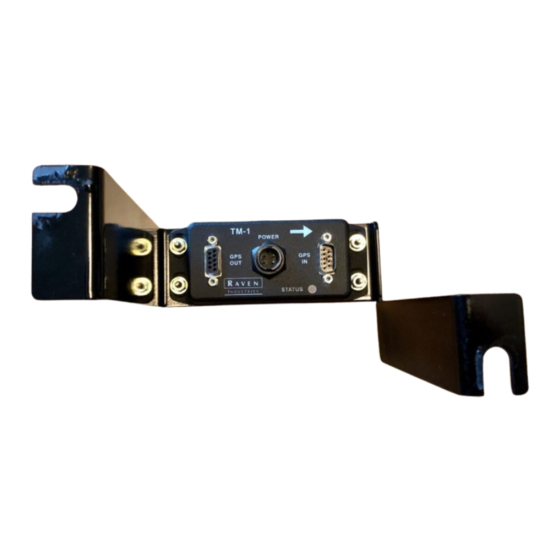
Page 6: Kit Contents
4-Pin Power GPS Input Status Indicator Since the TM-1 does not have a user interface, the TM-1 will need to be configured using a serial connection on a laptop, SmarTrax™ controller, or a Raven field computer. • Viper II™ or Viper Pro™... -
Page 7: Installation
C h a p t e r 2 Overview This chapter contains instructions for mounting the Raven TM-1 Tilt Module and routing the GPS signal to and from the sensor. Examples of system diagrams for widely used systems are included in Chapter 5, System Diagrams. -
Page 8: Power Connection
The green and white wires are not used. Routing GPS Signal In order for the TM-1 Tilt Module to provide a corrected GPS position for guidance and location, route a raw or uncorrected GPS signal from the DGPS receiver to the ‘GPS IN’ port on the TM-1. -
Page 9: Set Up & Configuration
To properly compensate machine position, the TM-1 must be calibrated for the antenna height above ground and the delay from the time satellite information is received until a position solution is determined (delay time). This chapter contains instructions for the various methods of calibrating these settings and setting up the TM-1 for operation. -
Page 10: Tm-1 Configuration Settings
Operator Zero When the unit is bolted in place, the TM-1 may register a small tilt angle. To calibrate for a level ground condition, and to eliminate error due to the mounting surface, the TM-1 should be calibrated on a known level surface. -
Page 11: Tm-1 Configuration
The antenna height setting is not displayed on the Tilt Configuration screen. Refer to the Cruizer Operator’s Manual for information on this setting. Compensation. Toggle this option ‘On’ to enable the TM-1 Tilt Module and to use tilt corrected GPS messages. -
Page 12: Using The Envizio Or Envizio Plus
Chapter 3 Current Tilt. This is a display only. This displays the current tilt angle observed by the TM-1 Tilt Module. Note: The maximum tilt angle which the TM-1 may register is ±45° from a level surface. Calibrate. On level ground, the current tilt display should read a zero tilt angle. If the display shows a non-zero tilt angle on known level ground, touch the Calibrate button located in the lower, left corner of the Tilt Configuration screen to recalibrate the TM-1 to a level condition. -
Page 13: Using The Envizio Pro Or Envizio Pro Ii
Using the Envizio Pro or Envizio Pro II If the TM-1 Tilt Sensor is connected directly to the DGPS connector on the main interface cable, the field computer may be used to configure the TM-1. Touch the Tilt icon to access the Tilt Configuration screen. -
Page 14: Using A Viper Ii Or Viper Pro
Operator Zero. On level ground the current reading should display a zero tilt angle. If the display shows a non- zero tilt angle on known level ground, touch the Operator Zero button to recalibrate the TM-1 to a level condition. -
Page 15: Using A Computer
• RFP Sim program available for download from the Raven web site: www.ravenhelp.com Connect the GPS OUT port on the TM-1 to a serial, or comm, port on a home or office computer using a standard DB-9 serial cable. Note: Standard serial cables (P/N 115-0171-215) may be ordered from Raven or purchased from many local retail stores. - Page 16 7 and step 8. Close the RFP Sim program and disconnect serial cable. To re-calibrate the TM-1 for level ground using a computer: Park on level ground. Type the $PSLIS,ILT,NULL command into blank box at bottom of RFP Sim program and click SEND. This will recalibrate the TM-1 sensor for level ground.
-
Page 17: Troubleshooting
Bypassing the TM-1 If an issue is experienced with the TM-1 in operation, bypass the Tilt Module by removing the DB-9 serial cable connectors from the ‘GPS IN’ and ‘GPS OUT’ ports on the TM-1 and connecting these two connectors together. -
Page 18: Status Indicator
Chapter 4 Status Indicator Before contacting a local Raven dealer for support, refer to the following table to help diagnose and correct possible issues with TM-1 operation. Note: The LED Status flash pattern consists of a set number of blinks, followed by a pause. The number of blinks indicates the current status according to the following table. -
Page 19: Chapter 5 System Diagrams
CHAPTER C h a p t e r 5 The following diagrams may be helpful for installing or troubleshooting the installation of the TM-1 Tilt Module. Additional system diagrams are available (free of charge) from the Raven Industries web site: www.ravenhelp.com... - Page 20 Chapter 5 TM-1 with Cruizer FIGURE 1. TM-1 Tilt Module Installation & Reference Manual...
- Page 21 System Diagrams TM-1 with Cruizer, SmarTrax, and Serial Console FIGURE 2. Manual No. 016-0171-049...
- Page 22 Chapter 5 TM-1 with Viper Pro and SmarTrax FIGURE 3. TM-1 Tilt Module Installation & Reference Manual...
- Page 23 System Diagrams TM-1 with Envizio Pro (Internal DGPS Receivers) FIGURE 4. Manual No. 016-0171-049...
- Page 24 Chapter 5 TM-1 with Envizio Pro and SmarTrax FIGURE 5. TM-1 Tilt Module Installation & Reference Manual...
- Page 25 System Diagrams TM-1 with Envizio Plus, Lightbar, and Raven Console FIGURE 6. Manual No. 016-0171-049...
- Page 26 Chapter 5 TM-1 with Envizio Plus and SmarTrax FIGURE 7. TM-1 Tilt Module Installation & Reference Manual...
- Page 27 How Can I Get Service? Bring the defective part and proof of purchase to your Raven dealer. If your dealer agrees with the warranty claim, the dealer will send the part and proof of purchase to their distributor or to Raven Industries for final approval.
Need help?
Do you have a question about the TM-1 and is the answer not in the manual?
Questions and answers