Table of Contents
Advertisement
Quick Links
Maintenance Manual
ML2480B Series, ML2490A Series
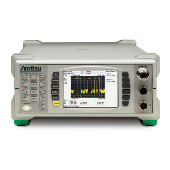
Wideband/Pulse Power Meter
ML2487A/B
Wideband Power Meter - Single Channel
ML2488A/B
Wideband Power Meter - Dual Channel
ML2495A
Pulse Power Meter - Single Channel
ML2496A
Pulse Power Meter - Dual Channel
Anritsu Company
Part Number: 13000-00164
490 Jarvis Drive
Revision: K
Morgan Hill, CA 95037-2809
Published: February 2015
USA
Copyright 2011 Anritsu Company
Advertisement
Table of Contents

Related Manuals for Anritsu ML2480B Series


Summary of Contents for Anritsu ML2480B Series
- Page 1 Maintenance Manual ML2480B Series, ML2490A Series Wideband/Pulse Power Meter ML2487A/B Wideband Power Meter - Single Channel ML2488A/B Wideband Power Meter - Dual Channel ML2495A Pulse Power Meter - Single Channel ML2496A Pulse Power Meter - Dual Channel Anritsu Company Part Number: 13000-00164...
- Page 3 Some or all of the following five symbols may or may not be used on all Anritsu equipment. In addition, there may be other labels attached to products that are not shown in the diagrams in this manual.
- Page 4 For Safety Warning Always refer to the operation manual when working near locations at which the alert mark, shown on the left, is attached. If the operation, etc., is performed without heeding the advice in the operation manual, there is a risk of personal injury.
-
Page 5: Table Of Contents
Table of Contents Chapter 1—General Information Introduction ..............1-1 Description . - Page 6 Table of Contents (Continued) Front Panel ..............2-3 LCD Display.
- Page 7 Table of Contents (Continued) 1 GHz Calibrator Power Level (ML248xx-Option 15, ML249xA) ..... . 3-14 50 MHz Calibrator VSWR Verification (All Models) ....... . 3-14 Required Equipment .
- Page 8 Table of Contents (Continued) Chapter 6—Removal and Replacement Procedures Introduction ..............6-1 Power Meter Disassembly .
- Page 9 Table of Contents (Continued) (ML248xx without Option 15)..........A-12 Section 4-7: RF Calibrator Output Power Adjustment (ML248xx without Option 15).
- Page 10 Table of Contents (Continued) Contents-6 PN: 13000-00164 Rev. K ML248xx, ML249xA MM...
-
Page 11: Chapter 1-General Information
A complete instrument description with performance specifications for each model can be found in the technical data sheet, Anritsu part number: 11410-00423, which is also available online. Updated versions of this manual and the technical data sheet may be downloaded from the Anritsu Internet site at: http://www.anritsu.com. -
Page 12: User Interface, Menus, And Soft Buttons
For example: Write HCCFVAL <New Value> Identification Number An Anritsu Power Meter ID number is affixed to the rear panel. Please use the complete ID number when ordering parts or corresponding with Anritsu Customer Service. Online Manual This manual is available on CD ROM as an Adobe Acrobat Portable Document Format (*.pdf) file. The file can be viewed using Acrobat Reader, a free program that is also included on the CD ROM. -
Page 13: Model Options And Accessories
Chapter 1 — General Information 1-7 Model Options and Accessories Model Options and Accessories ML248xA The ML248xA Power Meter is no longer available and has been replaced by the ML248xB. ML248xB The ML248xB Power Meter is available with either one or two sensor inputs. Model numbers, options, and accessories are listed below. -
Page 14: Ml249Xa
1-8 Service Policy Chapter 1 — General Information ML249xA The ML249xA Power Meter is available with either one or two sensor inputs. Model numbers, options, and accessories are listed below. ML249xA Models Table 1-6. Number of Sensor Channels Model Number Single input ML2495A Dual input... -
Page 15: Replaceable Parts
Replaceable Parts The following spare parts are available for the power meter. Refer to Chapter 6 for removal and replacement procedures. Contact your nearest Anritsu Customer Service or Sales Center for price and availability information. ML248xA Spare Parts Table 1-9. -
Page 16: 1-10 Test Equipment List
3-1). Table 1-12. Test Equipment List (1 of 2) Instrument Critical Specification Manufacturer/Model Usage Range Calibrator Anritsu ML2419A C, P Frequency Counter Anritsu MF2412B C, P RF Cable: BNC male connector at one end and BNC(m) to N(m) -
Page 17: Esd Requirements
An ESD safe work area and proper ESD handling procedures that conform to ANSI/ESD S20.20-1999 or ANSI/ESD S20.20-2007 is mandatory to avoid ESD damage when handling subassemblies or components found in Anritsu instruments. ML248xx, ML249xA MM PN: 13000-00164 Rev. K... - Page 18 1-11 ESD Requirements Chapter 1 — General Information PN: 13000-00164 Rev. K ML248xx, ML249xA MM...
-
Page 19: Chapter 2-Functional Description
Chapter 2 — Functional Description Product Overview The power meter is a lightweight, portable instrument featuring high accuracy and fast measurement speeds. The large front panel LCD provides simultaneous dual display channel readout with graphical display of pulse power measurements. Sensor Inputs and Amplifiers The ML2487x / ML2495A Power Meter features a single sensor input. -
Page 20: General Operation
2-2 General Operation Chapter 2 — Functional Description General Operation The power meter consists of several key blocks. Input Amplifier Each sensor input has its own dedicated, low noise, high speed amplifier. The CW amplifier is split into five ranges to cover the power range from –70 dBm to +20 dBm. Ranges 1 to 2 are DC coupled. Ranges 3 to 5 are used for low-level measurements. -
Page 21: Front Panel
Chapter 2 — Functional Description 2-6 Internal Construction Front Panel The front panel assembly is made up of a conductive contact rubber keypad sandwiched between the molded plastic front panel and the LCD PCB assembly. Depending upon the option configuration selected, the front panel may contain the signal channel input connectors and the RF calibrator reference output. -
Page 22: Data Entry Keypad
On standard model power meters, the signal channel A and B input connectors are mounted on the front panel. The connectors are 12-pin Hirose type. A sensor cable, provided with the meter, is used to connect an Anritsu power sensor to the signal channel. The connectors are snap push fit and require the outer body to be pulled to enable removal. -
Page 23: Gpib
Chapter 2 — Functional Description 2-10 Power Supply Operation GPIB A standard General Purpose Interface Bus connector is used to connect through GPIB to other test equipment and a host computer. The power meter series is compatible with IEEE-488.1/2 requirements. Refer to the power meter Remote Programming Manual for information on using GPIB. - Page 24 2-10 Power Supply Operation Chapter 2 — Functional Description PN: 13000-00164 Rev. K ML248xx, ML249xA MM...
-
Page 25: Chapter 3-Performance Verification
Chapter 3 — Performance Verification Introduction Performance of the Anritsu ML248xA, ML248xB and ML249xA Power Meters can be verified using the procedures in this chapter. Test Conditions The equipment used to verify the power meter is intended for use as calibration instruments, and as such must be operated under controlled conditions of temperature and humidity in order to meet its specified precision and stability. - Page 26 3-4 Input Range Verification Chapter 3 — Performance Verification Range Calibrator Figure 3-1. The performance verification tests will begin when the soft key for the sensor input to be verified is selected. 3. For single-channel power meters (ML2487A, ML2487B or ML2495A), press the A soft key. 4.
-
Page 27: Range Data Interpretation
6. The Data from the power meter display can be entered into an excel spreadsheet (*.xls) to verify the measurements. The part number of this spreadsheet is 63153. Contact your nearest Anritsu Customer Service or Sales center for an electronic copy of this spreadsheet. -
Page 28: Pass/Fail Criteria
3-4 Input Range Verification Chapter 3 — Performance Verification Pass/Fail Criteria The meter should be accepted as PASSED if it meets the error and linearity statistics listed in Table 3-2. Pass/Fail Criteria Table 3-2. Range Specifications (dB) –0.020 ≤ R1U ≤ 0.020 Range 1 Absolute Error –0.040 ≤... -
Page 29: 50 Mhz Calibrator Frequency (All Models)
The following procedure is used to measure the 50 MHz Calibrator output frequency of the ML248xx and ML249xA power meters. Required Equipment • Anritsu MF2412B Frequency Counter or equivalent • RF Cable with BNC male connection at one end and N-type male connection at other end. Procedure 1. - Page 30 3-5 50 MHz Calibrator Frequency (All Models) Chapter 3 — Performance Verification • Measurement Frequency: • F = Frequency from the MF2412B (in Hz) meas • Residual Error: meas ------------------- - × 1 10 ± × ------ - ...
-
Page 31: Ghz Calibrator Frequency (Ml248Xx-Option 15, Ml249Xa)
The following procedure is used to measure the 1 GHz Calibrator output frequency of the ML248xA and ML248xB power meters with option 15 and all ML249xA units. Required Equipment • Anritsu MF2412B Frequency Counter or equivalent • RF Cable with N-type male connection at both ends Procedure for 1 GHz Verification 1. -
Page 32: 50 Mhz Calibrator Power Level (All Models)
3-7 50 MHz Calibrator Power Level (All Models) Chapter 3 — Performance Verification • Measurement Frequency: = Frequency from the MF2412B (in Hz) meas • Residual Error: meas ------------------- - × 1 10 ± × ------ - ... - Page 33 Chapter 3 — Performance Verification 3-7 50 MHz Calibrator Power Level (All Models) ML248xx or ML249xA Agilent 34420A Nano Volt Meter Shift Agilent 8487B Power Sensor Agilent 432A Agilent 432A Power Meter (Front) Power Meter (Rear) 432 A POWER METER CALIBRATION FACTOR FINE ZERO mW - RANGE - dBm...
- Page 34 3-7 50 MHz Calibrator Power Level (All Models) Chapter 3 — Performance Verification 432 A POWER METER CALIBRATION FACTOR FINE ZERO mW - RANGE - dBm MOUNT RESISTANCE TANC TANCE Power Meter Settings Figure 3-4. 12. Press DCV 1-2 on the Agilent 34420A as shown in Figure 3-5.
-
Page 35: P Meas Calculation
Chapter 3 — Performance Verification 3-7 50 MHz Calibrator Power Level (All Models) Calculation meas 1. Use the equation below to determine P (the reference calibrator output power in Watts). Start by meas finding the Mismatch (M), then using this number, along with V0, V1, V , R, and EE to solve for comp . -
Page 36: Calibrator Power Level Uncertainty
3-7 50 MHz Calibrator Power Level (All Models) Chapter 3 — Performance Verification Table 3-3 shows an uncertainty calculation of an ML248xxA reference calibrator power level. The table shows the resulting expanded uncertainty and each source of uncertainty. Calibrator Power Level Uncertainty The formula for standard uncertainty is: ×... - Page 37 Chapter 3 — Performance Verification 3-7 50 MHz Calibrator Power Level (All Models) The standard uncertainty of each source of uncertainty in Table 3-3 is calculated as follows: – × × × × ------ - 0.00003 V -------------------------------------- - 0.000004 10V ...
-
Page 38: Ghz Calibrator Power Level (Ml248Xx-Option 15, Ml249Xa)
• Agilent N432A Power Meter • Agilent 8478B Power Sensor • Agilent 34401A DMM or equivalent • Anritsu S820E VNA or equivalent Recording Results Record measurements and calculations within this procedure, and record the final VSWR result within the Test Records on page A-11. - Page 39 Chapter 3 — Performance Verification 3-9 50 MHz Calibrator VSWR Verification (All Models) 10. Repeat step 4 through 9 to measure and record the measurements for the 200, 300, 400 Ohm settings. 11. Record the 4 resistance measurements below: = ______________ (A value near 100 ohms) = ______________ (A value near 200 ohms) = ______________ (A value near 300 ohms) = ______________ (A value near 400 ohms)
- Page 40 3-9 50 MHz Calibrator VSWR Verification (All Models) Chapter 3 — Performance Verification 19. Using the VSWR values from the previous step calculate the reflection coefficient, also known as Gamma (Γ) for each of the resistance values, using the following formula: VSWR 1 –...
- Page 41 Chapter 3 — Performance Verification 3-9 50 MHz Calibrator VSWR Verification (All Models) 50 MHz VSWR Table 3-4. Bridge Resistance Calibrator Setting Setting Measured Value COMP1 with RF Calibrator Off off= off= with RF Calibrator Off COMP1 COMP1 100 Ω with RF Calibrator On with RF Calibrator On COMP1...
- Page 42 3-9 50 MHz Calibrator VSWR Verification (All Models) Chapter 3 — Performance Verification 35. Calculate the variable Gamma S (ΓS) for the 100, 300 and 400 resistance values using the M variables from Step 34, the Gamma values from Step 19 and following equations.
-
Page 43: 3-10 1 Ghz Calibrator Vswr Verification
• Agilent N432A Power Meter • Agilent 8478B Power Sensor • Agilent 34401A DMM or equivalent • Anritsu S820E VNA, or equivalent Recording Results Record measurements and calculations within this procedure, and record the final VSWR result within the Test Records on page A-11. - Page 44 3-10 1 GHz Calibrator VSWR Verification Chapter 3 — Performance Verification 100, 200, 300 and 400 Ohm Bridge Resistance Measurement Figure 3-8. 12. Power off the N432A. 13. Attach the 8478B power sensor to the sensor cable. 14. Do not connect the power sensor to any source. 15.
- Page 45 Chapter 3 — Performance Verification 3-10 1 GHz Calibrator VSWR Verification 20. For each of the resistance settings, connect the 8478B to the RF Calibrator of the DUT, 21. On the N432A, toggle the front panel Display button so that menu 2 of 2 is displayed. 22.
- Page 46 3-10 1 GHz Calibrator VSWR Verification Chapter 3 — Performance Verification 1 GHz VSWR Table 3-5. Bridge Resistance Calibrator Setting Setting Measured Value COMP1 with RF Calibrator Off off= off= with RF Calibrator Off COMP1 COMP1 100 Ω with RF Calibrator On with RF Calibrator On COMP1 COMP1...
- Page 47 Chapter 3 — Performance Verification 3-10 1 GHz Calibrator VSWR Verification 35. Calculate the variable Gamma S (ΓS) for the 100, 300 and 400 resistance values using the M variables from Step 34, the Gamma values from Step 19 and following equations. Each equation will produce two numbers, record the number that is between -1 and +1, and discard the number outside of this range.
- Page 48 3-10 1 GHz Calibrator VSWR Verification Chapter 3 — Performance Verification 3-24 PN: 13000-00164 Rev. K ML248xx, ML249xA MM...
-
Page 49: Chapter 4-Adjustment
• ML2419A Range Calibrator • Frequency Counter Example: Anritsu MF2412A • Anritsu MA24xxA Series Power Sensor (not MA2411A) • Non-magnetic tuning wand with a screwdriver tip for 6-32 slotted cores • Agilent Analog Power Meter 432A to be used in conjunction with: •... -
Page 50: Dc Reference Calibration
4-5 DC Reference Calibration Chapter 4 — Adjustment DC Reference Calibration To calibrate the DC Reference: 1. Enter the power meter Service Mode by pressing the front panel keys as follows: System | Service | Diag | 0 | Enter 2. - Page 51 Chapter 4 — Adjustment 4-5 DC Reference Calibration ZTP17 ZTP205 ZTP205 (gnd) (+V) (+V) ZTP17 ML248xA ML248xB or ML249xA (gnd) R353 ML248xB Calibration Test and Adjustment Points Figure 4-1. ML248xx, ML249xA MM PN: 13000-00164 Rev. K...
-
Page 52: Rf Calibrator 50 Mhz Frequency (Ml248Xx Without Option 15)
4-8.) To calibrate the 50 MHz frequency of the reference: 1. Connect an RF frequency cable from the power meter RF calibrator output to an Anritsu MF2412B frequency counter. 2. Set the RF calibrator to ON at 0 dBm by pressing the front panel keys as follows: Cal/Zero | Calibrator | Calibrator RF A bright green indicator is displayed in the button when the calibrator is switched on. - Page 53 Chapter 4 — Adjustment 4-8 RF Calibrator 50 MHz Frequency and 50 MHz/1 GHz Output Power Measurement and Automation Explorer Figure 4-2. 6. Click Communicate with Instrument as shown in Figure 4-3. Communicate with Instrument Figure 4-3. ML248xx, ML249xA MM PN: 13000-00164 Rev.
-
Page 54: Setting Up The 50 Mhz Frequency
4-8 RF Calibrator 50 MHz Frequency and 50 MHz/1 GHz Output Power Chapter 4 — Adjustment 7. In the Send String box (Figure 4-4), type the commands listed below and use the Write or Query button to send and receive data to and from the power meter. Send-Receive Dialogue Figure 4-4. -
Page 55: Verifying Cal Data Was Saved
Chapter 4 — Adjustment 4-8 RF Calibrator 50 MHz Frequency and 50 MHz/1 GHz Output Power 7. Save the new 50 MHz and 1 GHz output level DAC values with the following command: Write HCCSAV<50MHz Level Value>,<1GHz Level Value>,<Calibration date in the form of MMDDYY>... - Page 56 4-8 RF Calibrator 50 MHz Frequency and 50 MHz/1 GHz Output Power Chapter 4 — Adjustment PN: 13000-00164 Rev. K ML248xx, ML249xA MM...
-
Page 57: Chapter 5-Troubleshooting
Contact your nearest Anritsu Customer Service or Sales center for price and availability information. The procedures in this chapter suggest the most likely remedies in a logical order of severity. It is best to follow the steps as presented in order to properly isolate the fault. -
Page 58: Fault: Measurement Problems With Input A Or Input B
5-3 Rear Panel Chapter 5 — Troubleshooting Recommended Action 1. Reprogram the power meter using the bootload method described in Section 7-3 Chapter 7, “Firmware Updates”. 2. Replace the front panel assembly. 3. Replace the control PCB assembly. Fault: Measurement Problems with Input A or Input B. Description Problems are encountered when calibrating, zeroing, or making power measurements with the power meter on Input A or B. -
Page 59: Fault: No Gpib Communication
Chapter 5 — Troubleshooting 5-4 General Faults 3. Replace the control PCB. Fault: No GPIB Communication Description: No GPIB communication occurs when connected to a compatible GPIB controller. Recommended Action 1. Reset the unit to factory defaults and try again. 2. - Page 60 5-4 General Faults Chapter 5 — Troubleshooting PN: 13000-00164 Rev. K ML248xx, ML249xA MM...
-
Page 61: Chapter 6-Removal And Replacement Procedures
Chapter 6 — Removal and Replacement Procedures Introduction Anritsu strongly recommends that power meter repair be performed by qualified technical personnel only. The preferred power meter service policy is the replacement of major sub assemblies or complete unit exchange program. - Page 62 6-2 Power Meter Disassembly Chapter 6 — Removal and Replacement Procedures J666 J300 J301 J302 Measurement PCB Mounting Screws (6) Measurement PCB Removal - ML2487/8A Figure 6-1. 4. Disconnect the MCX connectors from J302 and J666 on the measurement PCB. See Figure 6-1.
-
Page 63: 1Ghz Calibrator Pcb Removal
Chapter 6 — Removal and Replacement Procedures 6-2 Power Meter Disassembly 1GHz Calibrator PCB Removal 1. Remove the AC power cord. 2. Remove the six captive screws on the underside of the unit and remove the top cover. Ensure that the front and rear panels remain firmly in place during this operation. -
Page 64: Measurement Pcb Removal (Ml248Xb And Ml249Xa)
6-2 Power Meter Disassembly Chapter 6 — Removal and Replacement Procedures Measurement PCB Removal (ML248xB and ML249xA) 1. Remove the six screws and washers that mount the measurement PCB to its support standoffs as shown Figure 6-3. 2. Disconnect the MCX connectors from J302 and J666 on the measurement PCB. 3. -
Page 65: Main Control Pcb Removal
Chapter 6 — Removal and Replacement Procedures 6-2 Power Meter Disassembly Main Control PCB Removal 1. Remove the three screws that secure the control PCB to the lower case as shown in Figure 6-4 Control PCB Mounting Screws Main Control PCB Screw Removal Figure 6-4. - Page 66 6-2 Power Meter Disassembly Chapter 6 — Removal and Replacement Procedures 4. Turn the unit over and rest it on its lower case feet. 5. As shown in Figure 6-6 Figure 6-7, gently lift up the main control PCB and disconnect the line power cable at the PSU connector P1, which connects the rear panel to the PSU.
-
Page 67: Front Panel Removal
Chapter 6 — Removal and Replacement Procedures 6-2 Power Meter Disassembly Front Panel Removal The front panel assembly is removed from the control PCB. See Figure 6-8 Figure 6-9. 1. Disconnect the LCD backlight cable from J8 on the control PCB. 2. -
Page 68: Rear Panel Removal
6-2 Power Meter Disassembly Chapter 6 — Removal and Replacement Procedures Rear Panel Removal The rear panel is removed from the main control PCB. See Figure 6-10 Figure 6-11, depending on model. 1. Remove the two screws that hold the line power input module to the rear panel. Undo the nut that secures the earth cable to the rear panel stud. -
Page 69: Psu Assembly Removal
Chapter 6 — Removal and Replacement Procedures 6-2 Power Meter Disassembly PSU Assembly Removal 1. Remove the four screws that hold the PSU mounting bracket in the lower case as shown in Figure 6-12. Lift the PSU out of the lower case. 2. -
Page 70: Power Meter Reassembly
6-3 Power Meter Reassembly Chapter 6 — Removal and Replacement Procedures Power Meter Reassembly Installation of any assembly is the reverse of the disassembly procedure listed above. When rebuilding the meter, pay special attention the location and routing of the AC power cable that connects from the PSU at P1 to the rear panel, and the DC supply cable that connects from the PSU Caution at P2 to the control PCB. -
Page 71: Chapter 7-Firmware Updates
Section 7-3). 1. Connect the computer serial COM port to the power meter back panel RS-232 serial connector, using the Anritsu Serial Interface cable (P/N: B41323) or equivalent (refer to Section 7-4). 2. Apply power to the power meter and allow it to complete the POST (Power On Self Test). Power sensors need not be connected at this time. -
Page 72: Bootload Mode
Section 7-4). 3. Install a jumper (Anritsu P/N: 551-577) to J805 (BOOTSTRAP) located to the rear right hand side of the Control PCB board. This will force the power meter into the bootload mode when power is applied. 4. Apply AC power to the power meter. -
Page 73: Serial Interface Cable
Order Anritsu part number 2000-1544. The cable can also be assembled from the following readily available components: • 2 meters of 8-conductor cable (Anritsu P/N: 800-365). • 2 each, 9-pin female D-connectors. Assemble the cable according to the following connection diagram and description. - Page 74 7-4 Serial Interface Cable Chapter 7 — Firmware Updates PN: 13000-00164 Rev. K ML248xx, ML249xA MM...
-
Page 75: Introduction
Appendix A — Test Records Introduction This appendix provides tables for recording the results of the performance verification tests (Chapter 3) and the calibration procedures (Chapter 4). They jointly provide the means for maintaining an accurate and complete record of instrument performance. Some test records are customized to cover particular ML248xA, ML248xB and ML249xA options. -
Page 76: Section 3-4: Input Range Verification
A-3 Test Records Appendix A — Test Records ML248xx, ML249xA Firmware Revision: Operator: Serial Number: Date: Options: Section 3-4: Input Range Verification Measurements and Calculated Error Figure Measured Measured Error (dB) Error (dB) (dB) (dB) Expected (Meas–Expected) (Meas–Expected) Range Channel A Channel B Level CH A... -
Page 77: Error, Linearity And Range Change Calculations
Appendix A — Test Records A-3 Test Records ML248xx, ML249xA Firmware Revision: Operator: Serial Number: Date: Options: Error, Linearity and Range Change Calculations Calculated (dB) Results (Pass/Fail) Specification (dB) From Error Measurements in Above Table CH A CH B CH A & CH B CH A CH B Range 1 Abs Error... -
Page 78: Section 3-5: 50 Mhz Calibrator Frequency Verification (All Models
A-3 Test Records Appendix A — Test Records ML248xx, ML249xA Firmware Revision: Operator: Serial Number: Date: Options: Section 3-5: 50 MHz Calibrator Frequency Verification (All Models) Calibrator Frequency Uncertainty = __________________ Hz meas Residual Error: meas ------------------- - × ... -
Page 79: Section 3-6: 1 Ghz Calibrator Frequency Verification (Ml248Xx-Option 15, Ml249Xa
Appendix A — Test Records A-3 Test Records ML248xx, ML249xA Firmware Revision: Operator: Serial Number: Date: Options: Section 3-6: 1 GHz Calibrator Frequency Verification (ML248xx-Option 15, ML249xA) Calibrator Frequency Uncertainty = __________________ Hz meas Residual Error: meas ------------------- - × 1 10 ... -
Page 80: Section 3-7: 50 Mhz Calibrator Power Level Verification (All Models
A-3 Test Records Appendix A — Test Records ML248xx, ML249xA Firmware Revision: Operator: Serial Number: Date: Options: Section 3-7: 50 MHz Calibrator Power Level Verification (All Models) Pmeas Calculation Measured: = ___________ V = ___________ V Calculated: = ___________ V = ___________ V comp meas... -
Page 81: Calibrator Power Level Uncertainty
Appendix A — Test Records A-3 Test Records ML248xx, ML249xA Firmware Revision: Operator: Serial Number: Date: Options: Calibrator Power Level Uncertainty Equations for Uncertainty Calculations Standard Uncertainty Calculation × × Uncertainty SensitivityC ------------------------ - Standard Uncertainty X Divisor Source Uncertainty Calculations –... -
Page 82: Uncertainty Results: Ml24Xxx Reference Calibrator Output Power Level
A-3 Test Records Appendix A — Test Records Uncertainty Results: ML24xxx Reference Calibrator Output Power Level (V/Ohm) comp (V/Ohm) (V/Ohm) (Ω) (Ω) (W/Ohm) Combined Uncertainty (μW) Expanded Uncertainty (K = 2) (mW) Expanded Uncertainty (K = 2) (%) Expanded Uncertainty, P Lower, P Upper actual... -
Page 83: Section 3-8: 1 Ghz Calibrator Power Level Verification (Ml248Xx-Option 15, Ml249Xa
Appendix A — Test Records A-3 Test Records ML248xx, ML249xA Firmware Revision: Operator: Serial Number: Date: Options: Section 3-8: 1 GHz Calibrator Power Level Verification (ML248xx-Option 15, ML249xA) Pmeas Calculation Measured: = ___________ V = ___________ V Calculated: = ___________ V = ___________ V comp meas... -
Page 84: Calibrator Power Level Uncertainty
A-3 Test Records Appendix A — Test Records ML248xx, ML249xA Firmware Revision: Operator: Serial Number: Date: Options: Calibrator Power Level Uncertainty Equations for Uncertainty Calculations Standard Uncertainty Calculation × × Uncertainty SensitivityC ------------------------ - Standard Uncertainty X Divisor Source Uncertainty Calculations –... -
Page 85: Uncertainty Results: Ml24Xxx Reference Calibrator Output Power Level
Appendix A — Test Records A-3 Test Records ML248xx, ML249xA Firmware Revision: Operator: Serial Number: Date: Options: Uncertainty Results: ML24xxx Reference Calibrator Output Power Level (V/Ohm) comp (V/Ohm) (V/Ohm) (Ω) (Ω) (W/Ohm) Combined Uncertainty (μW) Expanded Uncertainty (K = 2) (mW) Expanded Uncertainty (K = 2) (%) Expanded Uncertainty, P Lower, P... -
Page 86: Section 4-5: Dc Reference Calibration
A-3 Test Records Appendix A — Test Records ML248xx, ML249xA Firmware Revision: Operator: Serial Number: Date: Options: Section 4-5: DC Reference Calibration DSP Cal 5 Measurement Voltage Test Points DSP Cal 6 Measurement Specification After Adjustment ______________VDC ______________VDC DSP6 = DSP5 ± 2mV ZTP17 (gnd) and ZTP205 (+V) Section 4-6: RF Calibrator 50 MHz Frequency Adjustment... -
Page 87: Appendix B-Specifications
Appendix B — Specifications ML2487/8A, ML2487/8B and ML2495/6A Technical Data Sheet The latest version of the Technical Data Sheet (Anritsu PN: 11410-00423) for the ML2487/8A, ML2487/8B and ML2495/6A Wideband Peak Power Meter, can be downloaded from the Anritsu Internet site: http://www.anritsu.com... - Page 88 B-1 ML2487/8A, ML2487/8B and ML2495/6A Technical Data Sheet Appendix B — Specifications PN: 13000-00164 Rev. K ML248xx, ML249xA MM...
-
Page 89: Appendix C-Connector Care
Appendix C — Connector Care Introduction This appendix provides instructions and discussion on the care and use of precision RF connectors. Connector Do’s and Don’ts • These are high frequency connectors so be gentle and handle them with care. • Avoid touching connector mating planes with bare hands. Natural skin oils and microscopic dirt particles are very hard to remove. -
Page 90: Visual Inspection
There are some dimensions that are critical for the mechanical integrity, non-destructive mating and electrical performance of the connector. Connector gauge kits are available for many connector types. Please refer to Anritsu Application Note 10200-00040. The mechanical gauging of coaxial connectors will detect and prevent the following problems:... -
Page 91: Pin Depth Dimensions
FEMALE MALE Figure C-1. N Connector Pin Depth Pin Depth Gauge Use an Anritsu Pin Depth Gauge or equivalent as shown below in Figure C-2 to accurately measure pin depths. 1 – Pin Depth Gauge with needle setting at zero. -
Page 92: Pin Depth Tolerances
While this will not cause any damage, it will result in a poor connection and a consequent degradation in performance. Table C-1. Pin Depth Tolerances and Gauge Settings Connector Type Pin Depth (Inches) Anritsu Gauge Setting +0.000 GPC-7 Same as pin depth –0.003 +0.003... -
Page 93: Teflon Tuning Washers
Appendix C — Connector Care C-6 Connector Cleaning Instructions Teflon Tuning Washers The center conductor on most RF components contains a small teflon tuning washer located near the point of mating (interface). This washer compensates for minor impedance discontinuities at the interface. The washer’s location is critical to the RF component’s performance. -
Page 94: Cleaning Procedure
C-6 Connector Cleaning Instructions Appendix C — Connector Care Cleaning Procedure 1. Remove loose particles on the mating surfaces, threads, and similar surfaces using low-pressure compressed air. 2. The threads of the connector should be cleaned with cotton swab. When connector threads are clean, the connections can be hand-tightened to within approximately one-half turn of the proper torque. -
Page 95: Connection And Disconnection Techniques
45 degrees of rotation for the final tightening with the torque wrench. Table C-2 below lists the Anritsu Company torque wrench and open end wrench part numbers for different connectors. Table C-2. Connector Wrench Requirements – Torque Wrenches and Settings – Open End Wrenches... - Page 96 C-8 Disconnection Procedure Appendix C — Connector Care PN: 13000-00164 Rev. K ML248xx, ML249xA MM...
- Page 97 Numerics to M Index Numerics 1 GHz reference, option ....1-3 FPGA, signal processing ....2-2 50 MHz calibrator .
- Page 98 N to Z measurements calibrator, all ..... 3-5–3-14 safety symbols ......Safety-1 input range .
- Page 100 Anritsu Company 490 Jarvis Drive Anritsu utilizes recycled paper and environmentally conscious inks and toner. Morgan Hill, CA 95037-2809 http://www.anritsu.com...
Need help?
Do you have a question about the ML2480B Series and is the answer not in the manual?
Questions and answers