Sign In
Upload
Manuals
Brands
Anritsu Manuals
Measuring Instruments
ML2488A
User Manuals: Anritsu ML2488A Wideband Power Meter
Manuals and User Guides for Anritsu ML2488A Wideband Power Meter. We have
2
Anritsu ML2488A Wideband Power Meter manuals available for free PDF download: Operation Manual, Maintenance Manual
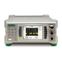
Anritsu ML2488A Operation Manual (297 pages)
Wideband Peak Power Meter
Brand:
Anritsu
| Category:
Measuring Instruments
| Size: 2 MB
Table of Contents
Limitation of Warranty
3
Notice about Documentation
3
Trademark Acknowledgements
3
Safety Symbols
4
For Safety
5
Declaration of Conformity (Ml248Xa)
6
Declaration of Conformity (Ml249Xa)
7
Table of Contents
8
Chapter 1. About this Manual
15
Purpose and Scope of this Manual
16
Your Comments on this Manual
16
Software Versions
16
Notification of Software Release
16
Using this Manual
17
Associated Documentation and Resources
19
Notation Conventions Used in this Manual
20
Chapter 2. Product Overview
21
About the Ml248Xa / Ml249Xa Peak Power Meter
22
Model Types
22
Features
23
Options and Accessories
24
Associated Sensors
25
Sensor Accessories
26
Associated Products
26
Chapter 3. Assembly and Connections
27
Initial Inspection
28
Shipped Items
28
Storage and Repackaging
29
Preparation for Storage
29
Environmental Requirements
29
Preparation for Shipment
29
Rack Mounting
29
Single Unit Rack Mounting (Option 01)
30
Tools Required
30
Assembly Procedure
31
Side-By-Side Rack Mounting (Option 03)
34
Tools Required
35
Assembly Procedure
35
Power Requirements
38
Environmental Requirements
38
Rear Panel Connections
39
Chapter 4. Front Panel Layout and Operation
41
Power-On Procedure
42
The Front Panel
43
The Numeric Keypad
44
The Hard Keys
46
The Screen
47
Sensor Information
48
Channel Information
49
Status Bar
52
The Soft Keys
53
Dialog Boxes
55
The Connectors
56
Data Entry Procedure
57
Numeric Entry Example
57
Text Entry
58
Power-Off Procedure
58
Chapter 5. Common Procedures
59
How Do I
60
Channel
68
Understanding and Setting up the Channels
68
Sensor Inputs
68
Channels
68
Modes
68
Measurement Displays
69
Channel Configuration Overview
70
Selecting the Measurement Mode
71
Selecting the Measurement Type
72
Selecting the Measurement Display Style
74
Selecting the Sensor Input (ML2488A and ML2496A Only)
75
Setting the Units of Measurement
77
Selecting the Resolution
78
Entering the Settling Percentage
79
Selecting Dual Display Channel Mode
80
Setting up the Second Channel
80
Displaying both Channels Simultaneously
81
Understanding Triggering
82
Selecting the Triggering Mechanism
83
Selecting the Type of Triggering
84
Entering the Triggering Capture Time
85
Random Repetitive Sampling (RRS) (Ml249Xa Only)
86
Entering the Triggering Delay
87
Enabling Auto Triggering
88
Entering the Triggering Level
89
Setting the Trigger Bandwidth (Ml249Xa Only)
90
Selecting the Trigger Arming Method
91
Entering a Frame Arming Level and Duration
92
Setting the Sampling Rate
93
Selecting the Trigger Indicator (Ml249Xa Only)
94
Linking the Channel Trigger Settings
95
Gates and Fences
96
Setting up and Enabling Gates and Fences
97
Viewing Gating Patterns
99
Setting the Active Gate
100
Setting up Repeat Gates
101
Averaging
102
Setting up Averaging
102
Enabling Averaging in Pulsed/Modulated Mode
103
Enabling Averaging in CW Mode
104
Restarting Averaging in Pulsed/Modulated Mode
104
Markers
105
Setting Markers
105
Turning All Markers off
106
Setting and Viewing the Active Marker
107
Positioning the Active Marker
107
Positioning the Delta Marker
108
Setting the Delta Marker Calculation
109
Linking the Delta Marker to the Active Marker
109
Moving the Active Marker to the Maximum Point
110
Moving the Active Marker to the Minimum Point
110
Zooming in or out on the Active Marker
110
Measuring the Pulse Rise Time
111
Measuring the Pulse Fall Time
112
Measuring the Pulse Width
113
Measuring the off Time
114
Measuring the Pulse Repetition Interval
115
Setting the Search Target Levels
116
Setting the Duty Cycle in CW Mode
117
Limits
118
Creating and Viewing Simple Limits
118
Creating and Saving Complex Limits
119
Recalling User or Predefined Complex Limits
121
Editing Complex Limits
122
Repeating Limits
123
Holding the Limit Fail Indicator
124
Sounding an Alarm on Limit Failure
124
Adjusting and Resetting the Trace Measurement Scale
125
Setting the Profile Display Style
126
Setting the Profile Display Data Hold Method
127
Holding Measurement Data in the Currently Active Channel
128
Setting the Peaking Indicator
128
Post Processing
129
Statistical Post Processing
130
PAE Post Processing
132
Setting the Cursor Position
133
Zooming in or out on the Cursor Position
133
Sensor
134
Setting up the Sensor in Use
134
Setting the Calibration Factor Applied to the Sensor
135
Setting the Power Offset Applied to the Sensors
137
Editing Cal Factor Tables
138
Creating New Cal Factor Tables
139
Editing the Sensor Offset Tables
140
Creating New Sensor Offset Tables
141
Holding Sensors on the Current Range
142
Cal/Zero
143
Zeroing the Sensor
143
Zeroing and Calibrating the Sensor
143
Performing a Zero Dbm Calibration
144
Zeroing the Rear Panel BNC Connector
144
System
145
Saving Instrument Settings
145
Recalling Instrument Settings
146
Capturing the Screen Image
148
Changing the Brightness of the Display Backlight
149
Setting the GPIB Address for the Instrument
150
Enabling Buffering of the GPIB Output
151
Setting the RS232 Serial Port Baud Rate
151
Configuring the Rear Panel Outputs
152
Turning the Key Click on or off
155
Setting Increment and Decrement Steps
155
Viewing the Instrument Identity Dialog
156
Turning the Security Feature on or off
156
Diagnostics
157
Upgrading the System Software
157
Preset
158
Resetting the System
158
Using the Preset Configurations
159
Chapter 6. Remote Operation
161
Overview of GPIB
161
Chapter 7. CW Setup and Measurement
163
Setting up the Power Meter for CW Measurements
163
Chapter 8. GSM Setup and Measurement
165
Setting up the Power Meter for GSM Measurements
165
Chapter 9. CDMA Setup and Measurement
169
Setting up the Power Meter for CDMA Measurements
169
EDGE Setup and Measurement
171
Setting up the Power Meter for EDGE Measurements
171
WLAN Setup and Measurement
175
Setting up the Power Meter for WLAN Measurements
175
802.11B, A, and G
175
Radar Setup and Measurement
177
Setting up the Power Meter for Radar Measurements
177
OFDM Setup and Measurement
179
Setting up the Power Meter for Continuous OFDM Measurements
179
Chapter 14. Examples of Dual Display Channel Operation
181
Displaying a Measurement in Different Units
181
Displaying a Pulsed/Modulated Measurement in Different Modes
182
Chapter 15. Dual Sensor Operation (ML2488A / ML2496A Only)
183
Displaying Measurements from Two Sensors Simultaneously
183
Chapter 16. ML2419A Range Calibrator
185
Overview of the ML2419A Range Calibrator
186
Initial Inspection
186
Power Requirements
186
Environmental Requirements
187
Rack Mounting
187
Storage and Shipment
187
Front Panel Connections
187
Rear Panel Connectors
188
Performing Verification
189
Interpreting the Results
191
Pass/Fail Criteria
191
Range Change Error
192
Using the Diagnostics Menu
192
Using the Range Calibrator Config Menu
193
Chapter 17. Secure Mode
195
Types of Memory
196
Secure Mode
196
Clearing the Non-Volatile Static RAM
196
Anritsu Power Sensors EEPROM
197
EEPROM Contents
197
Appendix A. the Command Hierarchies
199
Channel - Set up (Pulsed/Modulated
200
Channel - Set up (CW
201
Channel - Trigger - Trigger Source
202
Channel - Trigger - Set Capture Time
203
Channel - Trigger - Set Trigger Delay
204
Channel - Trigger - Trigger Level
205
Channel - Trigger - Trigger Bandwidth (Ml249Xa Only
206
Channel - Trigger - more - Arming
207
Channel - Trigger - more - Set Sample Rate
208
Channel - Trigger - more - Trigger Indication
209
Channel - Gating - Set up (Pulsed/Modulated
210
Channel - Gating (Cont) (Pulsed/Modulated
211
Channel - Relative Meas (CW
212
Channel - Averaging - Set Avg Number (Pulsed/Modulated
213
Channel - Averaging - Set Avg Number (CW
214
Channel - Markers - Position Act Mkr (Profile
215
Channel - Markers - Assign Act Mkr (Profile
216
Channel - Markers - Delta Marker - Position Delta Mkr (Profile
217
Channel - Markers - Set up (Profile
218
Channel - Markers - Marker Functions - Advanced Functions (Profile
219
Channel - Duty Cycle (CW
220
Channel - more - Limit Checking - Set up (Pulsed/Modulated
221
Channel - more - Limit Checking - Edit Limit Spec - Select Spec
222
Channel - more - Limit Checking - Edit Limit Spec - Save Spec
223
Channel - more - Limit Checking - Edit Limit Spec - Edit Segments
224
Channel - more - Limit Checking - Edit Limit Spec - Edit Title
225
Channel - more -Scaling (Profile
226
Channel - more - Profile Display (Profile
227
Channel - more - Peaking Indicator (Pulsed/Modulated
228
Channel - more - Peaking Indicator (CW
229
Channel - more - Post Process - Set up
230
Channel - more - Post Process - Cursor
231
Sensor - Setup
232
Sensor - Cal Factor
233
Sensor - Edit Tables
235
Sensor - Edit Tables - Edit Identity
236
Sensor - Edit Tables - Edit Offset Table
237
Cal/Zero
238
System - Save / Recall
239
System - Recall Settings
240
System - Config - Display - Set Screen Title
241
System - Config - Display - Backlight
242
System - Config - Remote - Set RS232 Baud Rate
243
System - Config - Rear Panel Config
244
System - Config - Set Inc/Dec Steps
245
System - Service - Identity
246
System - Service - Diag
247
System - Service - Upgrade
248
Preset
249
Appendix B. Specification
251
Appendix C. Default Values and Presets
262
Appendix D. ML2400A Reference Table
279
Appendix E. Terminology Glossary
281
Appendix F. Technical Support
283
Appendix G. Uncertainty Information
285
Uncertainty Examples
285
Appendix H. Frequently Asked Questions
287
Appendix I. Connector Care and Handling
289
Advertisement
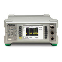
Anritsu ML2488A Maintenance Manual (100 pages)
Wideband/Pulse Power Meter
Brand:
Anritsu
| Category:
Measuring Instruments
| Size: 3 MB
Table of Contents
Table of Contents
5
Chapter 1-General Information
11
Introduction
11
Description
11
Documentation Conventions
11
Instrument Identification
11
Hard Keys or Front Panel Keys
11
User Interface, Menus, and Soft Buttons
12
User Interface Navigation Conventions
12
Identification Number
12
Online Manual
12
Related Manuals
12
Model Options and Accessories
13
Ml248Xa
13
Ml248Xb
13
Ml249Xa
14
Service Policy
14
Replaceable Parts
15
1-10 Test Equipment List
16
ESD Requirements
17
Chapter 2-Functional Description
19
Product Overview
19
Sensor Inputs and Amplifiers
19
Sensors
19
Internal Standard 50 Mhz Reference (Ml248Xx Only)
19
Option 15 Internal 50 Mhz and 1 Ghz Reference
19
Measurement Modes
19
General Operation
20
Input Amplifier
20
Signal Processing
20
Fpga
20
Digital Signal Processor (DSP)
20
Interface
20
GPIB Operation
20
Case Construction
20
Front Panel
21
Rear Panel
21
Handle and Rack Mount
21
Internal Construction
21
Measurement PCB
21
Control PCB
21
Power Supply
21
LCD Display
21
System Keys
21
Soft Keys
21
Data Entry Keypad
22
On/Standby Key
22
Front Panel Connectors
22
Sensor Inputs
22
RF Reference Calibrator
22
Rear Panel Connectors
22
Line Power Input
22
Ground Stud
22
RS-232 Port
22
Gpib
23
BNC I/O Ports
23
VGA out
23
Ethernet - 10/100 Base T LAN Interface
23
2-10 Power Supply Operation
23
Chapter 3-Performance Verification
25
Introduction
25
Test Conditions
25
Measurement Uncertainty
25
Input Range Verification
25
Required Equipment
25
Measurement Procedure
25
Range Data Interpretation
27
Pass/Fail Criteria
28
Absolute Error
28
Linearity
28
Range Change
28
50 Mhz Calibrator Frequency (All Models)
29
Required Equipment
29
Procedure
29
Calibrator Frequency Uncertainty
29
Ghz Calibrator Frequency (Ml248Xx-Option 15, Ml249Xa)
31
Required Equipment
31
Procedure for 1 Ghz Verification
31
Calibrator Frequency Uncertainty
31
50 Mhz Calibrator Power Level (All Models)
32
Required Equipment
32
Recording Results
32
Procedure
32
P Meas Calculation
35
Calibrator Power Level Uncertainty
36
Ghz Calibrator Power Level (Ml248Xx-Option 15, Ml249Xa)
38
50 Mhz Calibrator VSWR Verification (All Models)
38
Required Equipment
38
Recording Results
38
Procedure
38
3-10 1 Ghz Calibrator VSWR Verification
43
(Ml248Xx-Option 15, Ml249Xa)
43
Recording Results
43
Procedure
43
Chapter 4-Adjustment
49
Introduction
49
Required Test Equipment
49
Test Conditions
49
Pre-Test Setup
49
DC Reference Calibration
50
RF Calibrator 50 Mhz Frequency (Ml248Xx Without Option 15)
52
RF Calibrator Output Power (Ml248Xx Without Option 15)
52
RF Calibrator 50 Mhz Frequency and 50 Mhz/1 Ghz Output Power
52
Required Equipment
52
Preliminary Steps
52
Setting up the 50 Mhz Frequency
54
Setting up the 50 Mhz and 1 Ghz Levels
54
Verifying Cal Data was Saved
55
Chapter 5-Troubleshooting
57
Introduction
57
Front Panel and Display
57
Fault: no Display
57
Fault: Keys Inoperable: Display on
57
Fault: One or more Keys Inoperable: Display on and Operating
57
Fault: Measurement Problems with Input a or Input B
58
Fault: RF Calibrator
58
Rear Panel
58
Fault: Power Meter will Not Load Firmware
58
Fault: no GPIB Communication
59
Fault: Incorrect Operation of BNC Inputs or Outputs
59
General Faults
59
Fault: Power Meter Loses Non-Volatile Memory
59
Fault: Alarm Buzzer Does Not Sound
59
Chapter 6-Removal And Replacement Procedures
61
Introduction
61
Power Meter Disassembly
61
Tools Required
61
Measurement PCB Removal (ML2487/8A)
61
1Ghz Calibrator PCB Removal
63
Measurement PCB Removal (Ml248Xb and Ml249Xa)
64
Main Control PCB Removal
65
Front Panel Removal
67
Rear Panel Removal
68
PSU Assembly Removal
69
Power Meter Reassembly
70
Chapter 7-Firmware Updates
71
Introduction
71
Code Loader Program
71
Program Installation
71
Running the Program
71
Bootload Mode
72
Serial Interface Cable
73
Appendix A-Test Records
75
Introduction
75
Measurement Uncertainty
75
Test Records
75
Section 3-4: Input Range Verification
76
Measurements and Calculated Error Figure
76
Error, Linearity and Range Change Calculations
77
Section 3-5: 50 Mhz Calibrator Frequency Verification (All Models
78
Calibrator Frequency Uncertainty
78
Section 3-6: 1 Ghz Calibrator Frequency Verification (Ml248Xx-Option 15, Ml249Xa
79
Calibrator Frequency Uncertainty
79
Section 3-7: 50 Mhz Calibrator Power Level Verification (All Models
80
Pmeas Calculation
80
Calibrator Power Level Uncertainty
81
Uncertainty Results: Ml24Xxx Reference Calibrator Output Power Level
82
Expanded Uncertainty, P Actual Lower, P Actual Upper
82
Section 3-8: 1 Ghz Calibrator Power Level Verification (Ml248Xx-Option 15, Ml249Xa
83
Pmeas Calculation
83
Calibrator Power Level Uncertainty
84
Uncertainty Results: Ml24Xxx Reference Calibrator Output Power Level
85
Expanded Uncertainty, P Actual Lower, P Actual Upper
85
Section 3-9:50 Mhz Calibrator VSWR Verification (All Models
85
Section 3-10:1 Ghz Calibrator VSWR Verification (Ml248Xx with Opt. 15 and Ml249Xa
85
Section 4-5: DC Reference Calibration
86
Section 4-6: RF Calibrator 50 Mhz Frequency Adjustment
86
(Ml248Xx Without Option 15
86
Section 4-7: RF Calibrator Output Power Adjustment
86
Appendix B-Specifications
87
ML2487/8A, ML2487/8B and ML2495/6A Technical Data Sheet
87
Appendix C-Connector Care
89
Introduction
89
Connector Do's and Don'ts
89
Coaxial Connector Care
89
Visual Inspection
90
Connector Pin Depth Precautions
90
Pin Depth Dimensions
91
Pin Depth Gauge
91
Pin Depth Tolerances
92
Over Torquing Connectors
92
Teflon Tuning Washers
93
Mechanical Shock
93
Connector Cleaning Instructions
93
Cleaning Items Required
93
Important Cleaning Tips
93
Cleaning Procedure
94
Connection and Disconnection Techniques
95
Connection Procedure
95
Disconnection Procedure
95
Advertisement
Related Products
Anritsu ML2480B Series
Anritsu ML2487A
Anritsu ML2487B
Anritsu ML2488B
Anritsu ML248 A Series
Anritsu ML2400A-01
Anritsu ML2400A-11
Anritsu ML2400A-22
Anritsu ML2400A-26
Anritsu ML2400A-27
Anritsu Categories
Measuring Instruments
Test Equipment
Portable Generator
Control Unit
Thermometer
More Anritsu Manuals
Login
Sign In
OR
Sign in with Facebook
Sign in with Google
Upload manual
Upload from disk
Upload from URL