Table of Contents
Advertisement
Quick Links
Advertisement
Table of Contents

Related Manuals for Anritsu ML248 A Series


Summary of Contents for Anritsu ML248 A Series
- Page 1 ML248xA / ML249xA Wideband Peak Power Meter Operation Manual ML2487A and ML2488A software release 2.00 ML2495A and ML2496A software release 2.00 Originated by Anritsu Ltd, EMD, Stevenage, U.K. P/N: 13000-00162 REVISION: E CREATED September 2005 COPYRIGHT 2005 ANRITSU...
- Page 2 European Union. For Products placed on the EU market after August 13, 2005, please contact your local Anritsu representative at the end of the product's useful life to arrange disposal in accordance with your initial contract and the local law.
-
Page 3: Limitation Of Warranty
Notice about Documentation Anritsu has prepared this manual for use by Anritsu personnel and customers as a guide for the proper installation and operation of Anritsu equipment and computer programs. -
Page 4: Safety Symbols
Safety Symbols Used on Equipment and In Manuals Some or all of the following five symbols may be used on Anritsu equipment. In addition, there may be other labels attached to products that are not shown in the diagrams in this manual. -
Page 5: For Safety
For Safety Always refer to the operation manual when working near locations at which the alert mark, shown on the left, is attached. If operation is performed without heeding the advice in the operation manual, there is a risk of personal injury. In addition, the equipment performance may be reduced. -
Page 6: Declaration Of Conformity (Ml248Xa)
Product Safety: EN61010-1:2001 Anritsu Limited Nov. 2003 Date Nick Orchiston, Quality Assurance Manager European Contact:- For Anritsu product EMC & LVD information contact Anritsu Limited, EMD, Wiltron House, Rutherford Close, Stevenage Herts, SG1 2EF UK, (FAX 44-1438 740202) 13000-00162 September 2005... -
Page 7: Declaration Of Conformity (Ml249Xa)
Product Safety: EN61010-1:2001 Anritsu Limited Sept. 2005 Date Nick Orchiston, Quality Assurance Manager European Contact:- For Anritsu product EMC & LVD information contact Anritsu Limited, EMD, Wiltron House, Rutherford Close, Stevenage Herts, SG1 2EF UK, (FAX 44-1438 740202) 13000-00162 September 2005... -
Page 8: Table Of Contents
Table of Contents Warranty ........................i Limitation of Warranty....................i Notice about Documentation ..................i Trademark Acknowledgements ................i Safety Symbols......................ii For Safety ....................... iii Declaration of Conformity (ML248xA) ..............iv Declaration of Conformity (ML249xA) ..............v Chapter 1. About this Manual ..................1-1 Purpose and Scope of this Manual ................1-2 Your Comments on this Manual .................1-2... - Page 9 Environmental Requirements ................... 3-12 Rear Panel Connections................... 3-13 Chapter 4. Front Panel Layout and Operation ............4-1 Power-On Procedure....................4-2 The Front Panel......................4-3 The Numeric Keypad....................4-4 The Hard Keys......................4-6 The Screen ......................... 4-7 Sensor Information....................4-8 Channel Information..................... 4-9 Status Bar ......................
- Page 10 Random Repetitive Sampling (RRS) (ML249xA only)........5-28 Entering the Triggering Delay ...................5-29 Enabling Auto Triggering ..................5-30 Entering the Triggering Level..................5-31 Setting the Trigger Bandwidth (ML249xA only) ............5-32 Selecting the Trigger Arming Method ...............5-33 Entering a Frame Arming Level and Duration ............5-34 Setting the Sampling Rate ..................5-35 Selecting the Trigger Indicator (ML249xA only)............5-36 Linking the Channel Trigger Settings................5-37...
- Page 11 Editing Complex Limits ..................... 5-64 Repeating Limits....................... 5-65 Holding the Limit Fail Indicator ................. 5-66 Sounding an Alarm on Limit Failure ................. 5-66 Adjusting and Resetting the Trace Measurement Scale .......... 5-67 Setting the Profile Display Style ................5-68 Setting the Profile Display Data Hold Method ............5-69 Holding Measurement Data in the Currently Active Channel ........
- Page 12 Upgrading the System Software ................5-99 Preset ........................5-100 Resetting the System....................5-100 Using the Preset Configurations ................5-101 Chapter 6. Remote Operation..................6-1 Overview of GPIB .......................6-1 Chapter 7. CW Setup and Measurement..............7-1 Setting Up the Power Meter for CW Measurements...........7-1 Chapter 8. GSM Setup and Measurement ..............8-1 Setting Up the Power Meter for GSM Measurements ..........8-1 Chapter 9.
- Page 13 Chapter 17. Secure Mode ..................17-1 Types of Memory...................... 17-2 Secure Mode ......................17-2 Clearing the Non-Volatile Static RAM............... 17-2 Anritsu Power Sensors EEPROM ................17-3 EEPROM Contents....................17-3 Appendix A. The Command Hierarchies..............A-1 Channel – Set Up (Pulsed/Modulated) ...............A-2 Channel –...
- Page 14 Channel – More – Post Process – Set Up ............... A-32 Channel – More – Post Process – Cursor ............... A-33 Sensor – Setup ......................A-34 Sensor – Cal Factor ....................A-35 Sensor – Edit Tables ....................A-37 Sensor – Edit Tables – Edit Identity................. A-38 Sensor –...
-
Page 15: Chapter 1. About This Manual
Chapter 1. About this Manual This chapter provides: • Scope of information covered in this manual and contact address for your comments. • A summary of, and links to, each of the chapters in the manual. • A list of associated documentation and resources. •... -
Page 16: Purpose And Scope Of This Manual
To receive automatic notification of software releases, send a blank e-mail with the subject heading of “ML248xA / ML249xA Software Notification Request” to powermeter.support@eu.anritsu.com. You will receive an e-mail informing you that the new software is available for download from the site identified. -
Page 17: Using This Manual
About this Manual ML248xA / ML249xA Using this Manual Users are advised to read through this manual in its entirety before operating the power meter. The manual should be kept with the unit for reference purposes thereafter. A brief summary of each of the chapters is given below. If you are viewing the electronic version of this manual you can click on the chapter headings below to jump to the chapter in question. - Page 18 A glossary of acronyms commonly used in this manual or in technical documentation associated with power measurements. Appendix F Technical Support How to contact Anritsu if you require technical assistance. Appendix G Uncertainty Information An explanation of how to calculate the degree of possible measurement uncertainty.
-
Page 19: Associated Documentation And Resources
About this Manual ML248xA / ML249xA Associated Documentation and Resources In addition to this manual, the following documents and resources are available on the CD shipped with the power meter. Documents File type ML248xA / ML249xA Wideband Peak Power Meter Remote Programming Manual (English edition) ML248xA Datasheet ML249xA Datasheet... -
Page 20: Notation Conventions Used In This Manual
ML248xA / ML249xA About this Manual Notation Conventions Used in this Manual The following conventions have been adopted in this manual. Channel Hard keys on the unit are enclosed in a box with a grey background. Set Up Soft keys that display on the screen are enclosed in a box with a white background. -
Page 21: Chapter 2. Product Overview
Chapter 2. Product Overview This chapter provides: • Details of ML248xA / ML249xA features. • A list of power meter options. • Associated sensors and sensor accessories. • An overview of associated Anritsu products. 13000-00162 September 2005... -
Page 22: About The Ml248Xa / Ml249Xa Peak Power Meter
ML248xA / ML249xA Product Overview About the ML248xA / ML249xA Peak Power Meter The ML248xA / ML249xA is a wideband peak power meter for the 3G and radar pulse measurement market. It is the ideal product for performing accurate measurements on pulsed and modulated systems. -
Page 23: Features
Sampling of up to 64 MS/s (ML248xA) / 62.5 MS/s (ML249xA) is ideal for WCDMA, Radar, EDGE, and WLAN measurements. Compatibility The power meter is compatible with all MA2400A/B sensors used on the existing Anritsu power meter range. Remote interface The ML248xA and ML249xA support both the GPIB and RS232 interfaces. -
Page 24: Options And Accessories
ML248xA / ML249xA Product Overview Options and Accessories Option Details ML2400A-01 Rack Mount, single unit ML2400A-03 Rack Mount, side by side ML2400A-05 Front Bail Handle ML2480A-06 Rear Mount input A ML2480A-07 Rear Mount Input A and Reference ML2480A-08 Rear Mount inputs A, B and Reference ML2480A-09 Rear Mount Inputs A and B ML2490A-06... -
Page 25: Associated Sensors
Product Overview ML248xA / ML249xA Associated Sensors The following sensors, sensor options, and sensor accessories are available for use with the ML248xA / ML249xA. Power Sensors (-70 to + 20 dBm) Fast diode sensors Model No. Range MA2468D 10 MHz – 6 GHz MA2469D 10 MHz –... -
Page 26: Sensor Accessories
ML248xA / ML249xA Product Overview Note: Sensors MA2411B, MA2490A, and MA2491A can only be used with cable options ML2400A-20 and ML2400A-21. Sensor MA2411B requires the use of option 15 1GHz calibrator (ML248xA only). Sensor versions A-C are also fully compatible with both the ML248xA and ML249xA. -
Page 27: Chapter 3. Assembly And Connections
Chapter 3. Assembly and Connections This chapter provides: • Details of how to inspect the power meter upon delivery. • A list of shipped items. • Details of how to store and repack the power meter. • Rack mounting details and illustrations. •... -
Page 28: Initial Inspection
If the power meter is damaged mechanically, notify your local sales representative or Anritsu Customer Service Center. If either the shipping container is damaged or the cushioning material shows signs of stress, notify the carrier as well as Anritsu. Retain the shipping materials for the carrier's inspection. -
Page 29: Storage And Repackaging
Seal the carton using either shipping tape or an industrial stapler. If the instrument is being returned to Anritsu for service, mark the address of the appropriate Anritsu service center (refer to the address at the back of this manual), the Return Materials Authorization (RMA) number, and your return address on the carton in a prominent location. -
Page 30: Single Unit Rack Mounting (Option 01)
The procedure involves fitting the support bracket, front plate, base panel, and a rear support bracket to the ML248xA / ML249xA. The ML248xA / ML249xA can then be loaded and secured in the rack position. Kit Parts List Anritsu No. Description Quantity Max Torque... -
Page 31: Assembly Procedure
Assembly and Connections ML248xA / ML249xA Assembly Procedure Confirm the correct tools are available, the parts listed above are present and the assembly drawing is at hand. Remove all feet from the ML248xA / ML249xA using the tool supplied. See diagram and notes on the following pages. - Page 32 ML248xA / ML249xA Assembly and Connections Foot removal Removable foot tool 50210 Top / bottom case Foot removal To remove feet. Locate the removal tool into the recess of each foot located on the top and bottom faces of the covers. Once the removal tool has been located in the foot recess, apply gentle pressure downward.
- Page 33 Assembly and Connections ML248xA / ML249xA 13000-00162 September 2005...
-
Page 34: Side-By-Side Rack Mounting (Option 03)
The universal top and bottom covers have removable feet to allow the rack mount kit to be fitted. The procedure involves fitting support brackets and two rear support brackets, one to each unit. Kit Parts List Anritsu No Description Quantity Max.Torque... -
Page 35: Tools Required
Assembly and Connections ML248xA / ML249xA Tools Required • 1 Small Phillips screw driver • 1 Large Phillips screw driver • 1 Small Phillips torque screwdriver 10 cNm to 120 cNm • 1 Foot removal tool 50210 (supplied) • 1 Assembly drawing “ML2480/03 SIDE BY SIDE OPTION” Assembly Procedure Confirm the correct tools are available, the parts listed above are present and the assembly drawing is at hand. - Page 36 ML248xA / ML249xA Assembly and Connections Foot removal Removable foot tool 50210 Top / bottom case Foot Removal: To remove feet. Locate the removal tool into the recess of each foot located on the top and bottom faces of the covers. Once the removal tool has been located in the foot recess, apply gentle pressure downward.
- Page 37 Assembly and Connections ML248xA / ML249xA 13000-00162 3-11 September 2005...
-
Page 38: Power Requirements
ML248xA / ML249xA Assembly and Connections Power Requirements The ML248xA / ML249xA Power Meter is operated from an AC power line. The Power Meter is intended as an Installation (Overvoltage) Category II, Insulation Category I device. At power-on, the power meter will perform a brief power-on self test (POST). If a POST error occurs, information and available options will be displayed on the screen. -
Page 39: Rear Panel Connections
Assembly and Connections ML248xA / ML249xA Rear Panel Connections VGA Out Ethernet External Trigger V/GHz Input System RS232 GPIB / IEEE 488 WARNING WARNING Output 1 Output 2 NO OPERATOR SERVICEABLE DO NOT OPERATE WITH 85-264VAC PARTS INSIDE UNGROUNDED POWER CORD 47- 440 Hz 80VA Max USB connector (ML249xA only) - Page 40 ML248xA / ML249xA Assembly and Connections frequency. The correct calibration factor for this frequency is automatically interpolated and applied when in V/GHz calibration factor mode. Different scaling may be applied to sensor A or B allowing for measurement of frequency translation devices.
-
Page 41: Chapter 4. Front Panel Layout And Operation
Chapter 4. Front Panel Layout and Operation This chapter provides: • Details of the power-on procedure. • Illustrations and explanations of the front panel. • An explanation of the data entry procedure. 13000-00162 September 2005... -
Page 42: Power-On Procedure
ML248xA / ML249xA Front Panel Layout and Operation Before attempting to use the ML248xA / ML249xA it is first necessary to understand the layout and basic operation of the front panel. This chapter presents several detailed illustrations of the front panel and explains the operation of each of the component sections in turn. -
Page 43: The Front Panel
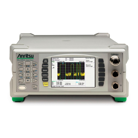
Front Panel Layout and Operation ML248xA / ML249xA The Front Panel Note: The illustration above shows the front panel of the ML2488A. With the exception of the model number itself, the front panel of the ML2496A is also identical. The ML2487A and ML2495A models have only one sensor connector. -
Page 44: The Numeric Keypad
ML248xA / ML249xA Front Panel Layout and Operation The Numeric Keypad ML2488A Power Meter Exit Back On/Standby Local [Exit] The [Exit] key is used to close a pop-up dialog and revert to the previous page of commands. Pressing this key when a field in a dialog has been selected for user input will result in entry of the number “7”... - Page 45 Front Panel Layout and Operation ML248xA / ML249xA [Sel] The [Sel] key is used to enable an entry field for input by the user. When the [Sel] key is pressed, the field is highlighted in white and a number of underscores are used to indicate the maximum length of permissible entry.
-
Page 46: The Hard Keys
ML248xA / ML249xA Front Panel Layout and Operation The Hard Keys The hard keys are used to display the associated soft key commands. When a hard key is pressed the commands within that group display next to the soft keys at the right of the screen. -
Page 47: The Screen
Front Panel Layout and Operation ML248xA / ML249xA The Screen The screen on the ML248xA / ML249xA can be sub-divided into several sections, each of which is illustrated and explained below. Sensor related information. Profile display icon. Channel related information. Area for profile and readout displays. -
Page 48: Sensor Information
ML248xA / ML249xA Front Panel Layout and Operation Sensor Information Sensor related information displays at the top of the screen (section A in the figure on the previous page). On the ML2487A / ML2495A there is one line of sensor information, and on the ML2488A / ML2496A, a second line is added beneath for sensor input B. -
Page 49: Channel Information
Front Panel Layout and Operation ML248xA / ML249xA Channel Information Channel related information displays at the left of the screen (section C in the main screen overview figure). 20MHz H D MM Channel ID (Ch1/ Ch2) Used to identify the channel being displayed on the screen. RRS mode flag (Channel >... - Page 50 ML248xA / ML249xA Front Panel Layout and Operation Trigger status (Channel > Trigger > Trigger Source) The first section of the trigger status icon conveys the settings at the “Source” and “Type” items in the [Trigger Set Up] dialog. External trigger, rising edge External trigger, falling edge Internal trigger, input A, rising edge Internal trigger, input A, falling edge...
- Page 51 Front Panel Layout and Operation ML248xA / ML249xA Measurement hold flag (Channel > More > Meas Hold) “H”: Measurement held “Blank space”: Measurement not held Data hold flag ([Pulsed / modulated mode] > Channel > More > Profile Display > Data Hold > Infinite) “D”: Data hold on.
-
Page 52: Status Bar
ML248xA / ML249xA Front Panel Layout and Operation Status Bar The status bar is used to display status information and error messages. If the instrument is in remote operation, one of the following is displayed at the right end of the status information line. -
Page 53: The Soft Keys
Front Panel Layout and Operation ML248xA / ML249xA The Soft Keys Channel Set Up Trigger Relative Meas Averaging Duty Cycle More The title of each menu grouping is shown at the top of the menu area. Each menu set contains a maximum of six commands at any one time, although some may contain only one or two. - Page 54 ML248xA / ML249xA Front Panel Layout and Operation Displays an additional page of soft keys. The fold in the lower right corner indicates to the user that there is more on the following page. Displays an additional page of soft keys and an input dialog for the key that was pressed.
-
Page 55: Dialog Boxes
Front Panel Layout and Operation ML248xA / ML249xA Dialog Boxes Dialog title bar. Setting items. The user can move between settings using the up and down arrows on the numerical keypad. Items that are not available for selection are grayed out, and these are skipped over when the user moves up and down the list. -
Page 56: The Connectors
ML248xA / ML249xA Front Panel Layout and Operation The Connectors Calibrator Calibrator Reference This connector is a precision female N- Type, 50 Ohm connector that provides a precision, traceable 0.0 dBm, 50 MHz or 1 GHz reference signal for absolute calibration of the sensors. -
Page 57: Data Entry Procedure
Front Panel Layout and Operation ML248xA / ML249xA Data Entry Procedure Numeric Entry Example The steps below serve as an example of how to enter a numeric value. Follow the steps carefully until you become familiar with the procedure. Press the Channel hard key followed by the Set Up soft key. -
Page 58: Text Entry
ML248xA / ML249xA Front Panel Layout and Operation Enter a value from the numeric keypad. If a digit is entered by mistake, use the [Clr] to delete the digit last entered. When entry is complete, press the Enter soft key to enter the value. The arrow keys on the numeric keypad can now be used to move the cursor to the next field if further entry is required. -
Page 59: Chapter 5. Common Procedures
Chapter 5. Common Procedures This chapter provides: • A quick reference table for locating the required procedure. • Details of procedures commonly performed on the ML248xA / ML249xA. 13000-00162 September 2005... -
Page 60: How Do I
ML248xA / ML249xA Common Procedures “How Do I …” Quick Reference Table The table below provides a quick reference to the procedures detailed in this chapter. Find the procedure required from the alphabetical listing in the “Procedure” column. Refer to the “Key combination” column for a summary of setting information. Turn to the listed page for detailed procedural steps or, if you are viewing the electronic version of this manual, click on the page number to jump to the associated page. - Page 61 Common Procedures ML248xA / ML249xA Procedure Key combination Page Delta marker calculation - select Markers 5-51 Channel Delta Marker Display Pwr Diff or Display Average Display - adjust brightness Config 5-91 System Display Backlight Duty cycle – setting in CW mode Duty Cycle 5-59 Channel...
- Page 62 ML248xA / ML249xA Common Procedures Procedure Key combination Page Limits – holding the display of More Limit 5-66 Channel the limit fail indicator Checking Fail Hold Limits – recalling complex limits More Limit 5-63 Channel Checking Set Up Select from soft keys Limits –...
- Page 63 Common Procedures ML248xA / ML249xA Procedure Key combination Page Markers – zoom in or out on Markers 5-52 Channel active marker Marker Functions Active Zoom In / Active Zoom Out Measurement – select type of Setup 5-14 Channel measurement to be made on Select “Measurement”...
- Page 64 ML248xA / ML249xA Common Procedures Procedure Key combination Page Pulse off time – measure Markers 5-56 Channel automatically. Marker Functions Advanced Functions Off Time Pulse repetition interval – Markers 5-57 Channel measure automatically Marker Functions Advanced Functions Pulse rise time – measure Markers 5-53 Channel...
- Page 65 Common Procedures ML248xA / ML249xA Procedure Key combination Page Screen image – capture. Config 5-90 System Display Screen Dump Mode Use screen capture program Screen titles – change name Config 5-89 System Display Set Screen Title Screen titles – display or hide Config 5-89 System...
- Page 66 ML248xA / ML249xA Common Procedures Procedure Key combination Page Sensor offset tables - editing Edit Tables 5-82 Sensor Edit Offset Tbl Sensor range hold – enable Set Up 5-76 Sensor Select “Range Hold” Range Hold Sensor- zero and calibrate Zero & Cal 5-85 Cal/Zero Zero &...
- Page 67 Common Procedures ML248xA / ML249xA Procedure Key combination Page Trigger - select indicator Trigger 5-36 Channel More Trigger indication Units of measurement – Config 5-97 System increment and decrement steps Inc / Dec Steps Units of measurement - select Set Up 5-19 Channel select “Units”...
-
Page 68: Channel
ML248xA / ML249xA Common Procedures Channel Understanding and Setting Up the Channels The ML248xA / ML249xA has either single or dual sensor inputs, two channels, two modes, and two measurement display options, and before explaining how these are set up, it is first important to ensure that the meanings and uses are fully understood. -
Page 69: Measurement Displays
Common Procedures ML248xA / ML249xA Measurement Displays There are two measurement displays available; “Readout” and “Profile”. The difference between the displays is explained below. Display Definition Profile: The measurement of the active channel is displayed as a graphical trace to which markers and gating patterns can be added. -
Page 70: Channel Configuration Overview
ML248xA / ML249xA Common Procedures Channel Configuration Overview The figure below summarizes the information above. It shows that both channels can be configured independently to almost any combination of settings. The information in parentheses shows settings that are not available on the ML2487A or ML2495A, or those that are unavailable due to specific setting combinations. -
Page 71: Selecting The Measurement Mode
Common Procedures ML248xA / ML249xA Selecting the Measurement Mode Press the Channel hard key to display the Channel group of commands. Press the Set Up soft key to display the [Channel Set Up] dialog for the channel that is currently active. The dialog will open with the “Mode” item already selected. Use the soft keys to select the required mode. -
Page 72: Selecting The Measurement Type
ML248xA / ML249xA Common Procedures Selecting the Measurement Type Press the Channel hard key to display the [Channel] group of commands. Press the Set Up soft key to display the [Channel Set Up] dialog. Make sure that the “Channel” item in the dialog is displaying the channel for which the settings are required. - Page 73 Common Procedures ML248xA / ML249xA Note: The “Measurement” item is not available in CW mode. Note: It is important to note the difference between Max and Peak in the settings above. Max represents the highest averaged value acquired over each section of the signal. This Max value can differ to Peak value considerably in that Peak represents the highest value taken from the raw samples.
-
Page 74: Selecting The Measurement Display Style
ML248xA / ML249xA Common Procedures Selecting the Measurement Display Style Press the Channel hard key to display the Channel group of commands. Press the Set Up soft key to display the [Channel Set Up] dialog for the channel that is currently active. Press the down arrow on the numeric keypad to select the “Meas Display”... -
Page 75: Selecting The Sensor Input (Ml2488A And Ml2496A Only)
Common Procedures ML248xA / ML249xA Selecting the Sensor Input (ML2488A and ML2496A only) Press the Channel hard key to display the Channel group of commands. Press the Set Up soft key to display the [Channel Set Up] dialog for the channel that is currently active. - Page 76 ML248xA / ML249xA Common Procedures Input is taken from sensor A. Input is taken from sensor B. Take input from the rear panel BNC, “Input 2, Analog”. Voltage Sensor measurement A is divided by sensor measurement B and displayed on the current channel. Sensor measurement B is divided by sensor measurement A and displayed on the current channel.
-
Page 77: Setting The Units Of Measurement
Common Procedures ML248xA / ML249xA Setting the Units of Measurement Press the Channel hard key to display the Channel group of commands. Press the Set Up soft key to display the [Channel Set Up] dialog for the channel that is currently active. Press the down arrow on the numeric keypad to select the “Units”... -
Page 78: Selecting The Resolution
ML248xA / ML249xA Common Procedures Selecting the Resolution Press the Channel hard key to display the Channel group of commands. Press the Set Up soft key to display the [Channel Set Up] dialog for the channel that is currently active. Press the down arrow on the numerical keypad to select “Resolution”. -
Page 79: Entering The Settling Percentage
Common Procedures ML248xA / ML249xA Entering the Settling Percentage The settling value allows some control over the tradeoff between speed and the extent to which a measurement has settled to its final value. A 1% settling time value relates to approximately 0.04 dB. -
Page 80: Selecting Dual Display Channel Mode
ML248xA / ML249xA Common Procedures Selecting Dual Display Channel Mode As explained earlier in this chapter, the ML248xA / ML249xA allows the user to measure power on two channels. There are a number of possible scenarios when this may be of use, such as to display the same measurement in different units, or to measure power at different points on the same test system. -
Page 81: Displaying Both Channels Simultaneously
Common Procedures ML248xA / ML249xA Displaying Both Channels Simultaneously Press the Channel hard key to display the Channel group of commands. Press the Set Up soft key to display the [Channel Set Up] dialog for the channel that is currently active. The active channel is identified at the “Channel” item at the top of the dialog. -
Page 82: Understanding Triggering
ML248xA / ML249xA Common Procedures Understanding Triggering The following pages explain each of the settings in the [Trigger Set Up] dialog. The figure below provides an overview of the meaning of each setting. The black area in the figure represents the screen on the ML248xA / ML249xA. 5-24 13000-00162 September 2005... -
Page 83: Selecting The Triggering Mechanism
Common Procedures ML248xA / ML249xA Selecting the Triggering Mechanism Press the Channel hard key to display the [Channel] group of commands. Press the Trigger soft key to display the [Trigger] menu and then press the Trigger Source soft key to display the screen shown below. Use the soft keys to select the triggering source. -
Page 84: Selecting The Type Of Triggering
ML248xA / ML249xA Common Procedures Selecting the Type of Triggering Press the Channel hard key to display the [Channel] group of commands. Press the Trigger soft key to display the [Trigger] menu and then press the Trigger Source soft key to display the screen shown below. Note: The triggering type cannot be specified if the trigger source is set to “Continuous”. -
Page 85: Entering The Triggering Capture Time
Common Procedures ML248xA / ML249xA Entering the Triggering Capture Time The capture time represents the amount of data displayed on the screen at any one time. If a positive value is entered at the “Delay” item, the capture time will commence once the specified delay has been reached. -
Page 86: Random Repetitive Sampling (Rrs) (Ml249Xa Only)
ML248xA / ML249xA Common Procedures Random Repetitive Sampling (RRS) (ML249xA only) As shown in the table on the previous page, if the capture time is set to a value less than 3.2 µs, a random repetitive sampling (RRS) method is used to acquire the data. RRS is selected automatically as necessary by the power meter and no user setting is required. -
Page 87: Entering The Triggering Delay
Common Procedures ML248xA / ML249xA Entering the Triggering Delay A trigger delay allows the user to impose a time lag (positive or negative) between the trigger event and the data displayed on screen. Specifying a positive delay has the affect of zooming in on a section of the pulse occurring some time after the trigger event. -
Page 88: Enabling Auto Triggering
ML248xA / ML249xA Common Procedures Enabling Auto Triggering Both the ML248xA and the ML249xA units can be configured to trigger automatically as detailed below. When auto triggering is enabled for the ML248xA the user must manually set a trigger level for each of the three ranges. For the ML249xA, the trigger level is specified automatically and no additional setting is required on the part of the operator. -
Page 89: Entering The Triggering Level
Common Procedures ML248xA / ML249xA Entering the Triggering Level Press the Channel hard key to display the [Channel] group of commands. Press the Trigger soft key to display the [Trigger] menu and then press the Trigger Level > Set Trig Level.. soft keys to display the [Set Trigger Level] dialog shown below. -
Page 90: Setting The Trigger Bandwidth (Ml249Xa Only)
ML248xA / ML249xA Common Procedures Setting the Trigger Bandwidth (ML249xA only) Press the Channel hard key to display the [Channel] group of commands. Press the Trigger soft key to display the [Trigger] menu and then press the Trigger Bandwidth soft keys to display the [Trigger BW] group of commands shown below. -
Page 91: Selecting The Trigger Arming Method
Common Procedures ML248xA / ML249xA Selecting the Trigger Arming Method Press the Channel hard key to display the [Channel] group of commands. Press the Trigger soft key to display the [Trigger] menu and then press More followed by Arming to display the screen shown below. Note: Arming settings cannot be made if the Trigger source item is set to “Continuous”. -
Page 92: Entering A Frame Arming Level And Duration
ML248xA / ML249xA Common Procedures Entering a Frame Arming Level and Duration As explained on the previous page, a frame arming level and duration can be specified to find the off period of a pulsed waveform. The trigger is re-armed only on the condition that the signal stays below the specified level for the specified duration. -
Page 93: Setting The Sampling Rate
Common Procedures ML248xA / ML249xA Setting the Sampling Rate This function allows the user to set the sampling rate for the active channel. Note: The sampling rate is only applicable to pulsed/modulated measurements. Press the Channel hard key to display the [Channel] group of commands. Press the Trigger soft key to display the [Trigger] menu and then press More followed by Set Sample Rate to display the [Set Sample Rate] dialog shown below. -
Page 94: Selecting The Trigger Indicator (Ml249Xa Only)
ML248xA / ML249xA Common Procedures Selecting the Trigger Indicator (ML249xA only) When the ML249xA is operating in pulsed modulated mode with an internal or external trigger source, the user can display the trigger point as either a small arrow at the bottom of the trace, or as an additional stepped waveform Press the Channel... -
Page 95: Linking The Channel Trigger Settings
Common Procedures ML248xA / ML249xA Linking the Channel Trigger Settings The trigger settings for channel 1 and channel 2 can be linked in the manner described below. The channels can only be linked when the “Mode” setting in the [Channel Set Up] dialog is the same for both channels. -
Page 96: Gates And Fences
ML248xA / ML249xA Common Procedures Gates and Fences Up to four different gating patterns may be applied simultaneously to any measurement. Before going on to describe how the gates and fences are set up, it is first necessary to make sure that the terms themselves are understood. Term Definition Gate:... -
Page 97: Setting Up And Enabling Gates And Fences
Common Procedures ML248xA / ML249xA Setting Up and Enabling Gates and Fences Press the Channel hard key to display the [Channel] group of commands. Press the Gating soft key followed by the Set Up soft key to display the [Gating Set Up] dialog. - Page 98 ML248xA / ML249xA Common Procedures Note: The difference between an active gate and an enabled gate should be made clear. Enabled An enabled gate is a gate that has been enabled for viewing but one for which measurement data is not made available unless operating the ML248xA / ML249xA remotely over a GPIB connection.
-
Page 99: Viewing Gating Patterns
Common Procedures ML248xA / ML249xA Viewing Gating Patterns Press the Channel hard key to display the Channel group of commands. Press the Gating soft key. Press the Display Gates soft key to display the gates on the profile as shown in the figure below. -
Page 100: Setting The Active Gate
ML248xA / ML249xA Common Procedures Setting the Active Gate Up to four gates can be enabled and viewed simultaneously on the profile display. In this situation, the gate that is currently active is shown on the display by a green box around the number at the base on the start and stop positions. -
Page 101: Setting Up Repeat Gates
Common Procedures ML248xA / ML249xA Setting Up Repeat Gates To facilitate the measurement of sequences on a regular basis, the user can select to repeat gate 1. Follow the procedure below to make the gate repetition settings. Press the Channel hard key to display the Channel group of commands. -
Page 102: Averaging
ML248xA / ML249xA Common Procedures Averaging The averaging settings allow the user to specify a given number of measurements over which the average result is then calculated. The commands found within the [Averaging] menu differ depending on whether the channel mode is set to Pulsed/Modulated or CW. Explanations in this section apply to both modes unless otherwise stated. -
Page 103: Enabling Averaging In Pulsed/Modulated Mode
Common Procedures ML248xA / ML249xA Enabling Averaging in Pulsed/Modulated Mode Press the Channel hard key to display the [Channel] group of commands. Press the Averaging soft key to display the [Averaging] menu. Press the Averaging soft key to toggle averaging between on and off. When averaging is enabled, the LED on the soft key is lit green. -
Page 104: Enabling Averaging In Cw Mode
ML248xA / ML249xA Common Procedures Enabling Averaging in CW Mode Press the Channel hard key to display the [Channel] group of commands. Press the Averaging soft key to display the [Averaging] menu. There are four averaging settings available as detailed below. Setting Meaning Off:... -
Page 105: Markers
Common Procedures ML248xA / ML249xA Markers The ML248xA / ML249xA can display up to four markers and one delta marker on a profile display at any time. Each of the markers is assigned a number, and the marker that is set up as the active marker is shown on screen by a number in a blue box. -
Page 106: Turning All Markers Off
ML248xA / ML249xA Common Procedures Use the arrows on the keypad to select the marker, and then enter the required position using either of the methods detailed below. • Use the Inc and Dec soft keys to increment or decrement the displayed value. •... -
Page 107: Setting And Viewing The Active Marker
Common Procedures ML248xA / ML249xA Setting and Viewing the Active Marker Press the Channel hard key followed by the Markers soft key to display the Markers group of commands. Press the Assign Act Mkr soft key and select the marker to serve as the active marker. -
Page 108: Positioning The Delta Marker
ML248xA / ML249xA Common Procedures Positioning the Delta Marker Two methods are available to position the delta marker. Method 1 Press the Channel hard key followed by the Markers soft key to display the [Markers] group of commands. Press the Delta Marker soft key to display the [Delta Mkr] group of commands. Press the Delta Marker soft key to enable the display of the delta marker. -
Page 109: Setting The Delta Marker Calculation
Common Procedures ML248xA / ML249xA Setting the Delta Marker Calculation The delta marker can be used to show either of the following calculations: • The difference in power level between the delta marker and the active marker. • The average power between the delta marker and the active marker. In both cases, the calculated value is shown on the screen at the active marker measurement readout. -
Page 110: Moving The Active Marker To The Maximum Point
ML248xA / ML249xA Common Procedures Moving the Active Marker to the Maximum Point Press the Channel hard key followed by the Markers soft key to display the [Markers] group of commands. Press the Marker Functions soft key to display the [Mkr Funcs] group of commands. Press the Active to Max soft key. -
Page 111: Measuring The Pulse Rise Time
Common Procedures ML248xA / ML249xA Measuring the Pulse Rise Time The rise time of the pulse that the active marker is currently position on can be calculated automatically as described below. The delta marker is set by default to the 90% linear power point on the rising edge, and the active marker is set to the 10% linear power point. -
Page 112: Measuring The Pulse Fall Time
ML248xA / ML249xA Common Procedures Measuring the Pulse Fall Time The fall time of the pulse that the active marker is currently positioned on can be calculated automatically as described below. The delta marker is set by default to the 10% linear power point on the falling edge, and the active marker is set to the 90% linear power point. -
Page 113: Measuring The Pulse Width
Common Procedures ML248xA / ML249xA Measuring the Pulse Width The width of the pulse that the active marker is currently positioned on can be calculated automatically as described below. The delta marker is set to the 50% linear power point on the falling edge, and the active marker is set to the 50% linear power point on the rising edge. -
Page 114: Measuring The Off Time
ML248xA / ML249xA Common Procedures Measuring the Off Time The off time of the pulse that the active marker is currently positioned on can be calculated automatically as described below. The active marker is set to the 50% point on the falling edge, and the delta marker is set to the 50% point on the rising edge of the next pulse. -
Page 115: Measuring The Pulse Repetition Interval
Common Procedures ML248xA / ML249xA Measuring the Pulse Repetition Interval The repetition interval of the pulse that the active marker is currently positioned on can be calculated automatically as described below. The active marker is set to the 50% point on the rising edge, and the delta marker is set to the 50% point on the rising edge of the next pulse. -
Page 116: Setting The Search Target Levels
ML248xA / ML249xA Common Procedures Setting the Search Target Levels This function is used to set the upper and lower target levels for the pulse rise and fall time searches. It is also used to select the search start source. Press the Channel hard key followed by the Markers soft key to display the [Markers]... -
Page 117: Setting The Duty Cycle In Cw Mode
Common Procedures ML248xA / ML249xA Setting the Duty Cycle in CW Mode This menu is used to set up and apply duty cycle correction to the currently active channel in CW mode. Ensure that the currently active channel is set to CW mode. Press the Channel hard key followed by the Duty Cycle soft key. -
Page 118: Limits
ML248xA / ML249xA Common Procedures Limits Upper and lower limits can be used during measurement to check that the results of measurement fall within an acceptable range. Limits can be set up by using one of those already defined within the instruments firmware, or by creating either a simple or complex limit specification. -
Page 119: Creating And Saving Complex Limits
Common Procedures ML248xA / ML249xA Creating and Saving Complex Limits A complex limit is one with multiple segments that allow the user to change the limit at, for example, different points in time along a GSM burst. Each segment within the complex limit is defined by specifying a point in time relative to the trigger point and an associated power level. - Page 120 ML248xA / ML249xA Common Procedures Press the Save Spec soft key followed by the Save as soft key. Use the hard or soft key arrows to select a vacant slot within the [User Limits] dialog, and then press Select . Press [Exit] to close the specifications table and then press the Set Up soft key to open the [Limit Checking Set Up] dialog.
-
Page 121: Recalling User Or Predefined Complex Limits
Common Procedures ML248xA / ML249xA Recalling User or Predefined Complex Limits Once created and saved in the manner described above, the user can quickly and easily recall any of the limit specifications. In addition to the user defined specifications, a number of predefined limit specifications are also available. -
Page 122: Editing Complex Limits
ML248xA / ML249xA Common Procedures Editing Complex Limits User generated limit settings can be opened, edited as required, and then resaved or saved under a different name. Predefined limits can be opened and edited and saved under a new name to a vacant slot in the [User Limits] dialog. -
Page 123: Repeating Limits
Common Procedures ML248xA / ML249xA Repeating Limits Complex limits can be repeated up to 8 times. Press the Channel hard key followed by the More soft key. Press the Limit Checking soft key to display the [Lim Check] group of commands. Press the Set Up soft key to display the [Limit Checking Set Up] dialog. -
Page 124: Holding The Limit Fail Indicator
ML248xA / ML249xA Common Procedures Holding the Limit Fail Indicator Fail Hold can be used to prevent the “Fail” flag in the channel information area reverting to “Pass” if subsequent measurements fall back within the limit specifications. Press the Channel hard key followed by the More soft key. -
Page 125: Adjusting And Resetting The Trace Measurement Scale
Common Procedures ML248xA / ML249xA Adjusting and Resetting the Trace Measurement Scale Press the Channel hard key followed by the More soft key. Press the Scaling soft key to display the [Scaling] group of commands. The reference level and scale can be set by selecting either Set Ref or Set Scale and using the Inc and Dec soft keys, or by pressing [Sel] and then entering a number at the keypad. -
Page 126: Setting The Profile Display Style
ML248xA / ML249xA Common Procedures Setting the Profile Display Style The digital signal processor uses a number of algorithms to determine how the measurements made are processed and thereafter displayed on the screen as one of the points on the profile display. By default each point on the profile represents the average of multiple measurements although this can be changed by the user to show the minimum, the maximum, or both. -
Page 127: Setting The Profile Display Data Hold Method
Common Procedures ML248xA / ML249xA Setting the Profile Display Data Hold Method Press the Channel hard key followed by the More soft key. Press the Profile Display soft key to display the [Prof Disp] group of commands. Press the Data Hold soft key to display the [Data Hold] group of commands. Note: The Data Hold soft key in not available if profile display setting detailed on the previous page is set to Avg. -
Page 128: Holding Measurement Data In The Currently Active Channel
ML248xA / ML249xA Common Procedures Holding Measurement Data in the Currently Active Channel Press the Channel hard key followed by the More soft key. Press the Meas Hold soft key to hold the measurement data in the currently active channel. The measurement data is not updated whilst being held in this manner. The LED on the soft key is lit green when measurement hold functionality has been enabled. -
Page 129: Post Processing
Common Procedures ML248xA / ML249xA Post Processing The post processing related soft keys allow statistical analysis or PAE of the measurement data for the currently active channel. Press the Channel hard key followed by the More soft key. Press the Post Process soft key to display the [Post Proc] group of commands. Press the Post Process soft key to turn post processing functionality on. -
Page 130: Statistical Post Processing
ML248xA / ML249xA Common Procedures Statistical Post Processing Select the “Type” item in the [Post Processing Set Up] dialog and press the Stats soft key. Press the down arrow on the numeric keypad to select the “Source” item. There are three options available at this item, the meanings of which are detailed in the table below. - Page 131 Common Procedures ML248xA / ML249xA CCDF Applies a Complementary Cumulative Density Function to the data, displaying a plot of the percentage of samples in which measurements lie at or above a given value. Press the down arrow on the numeric keypad to select the “Start Power” and “Stop Power”...
-
Page 132: Pae Post Processing
ML248xA / ML249xA Common Procedures PAE Post Processing The PAE setting is available on the ML2488A and ML2496A only. It allows the user to display the power added efficiency of an amplifier connected to the sensors on the A and B inputs on the front of the power meter. -
Page 133: Setting The Cursor Position
Common Procedures ML248xA / ML249xA Note : When PAE is enabled, the input configuration of the ML2488A / ML2496A is automatically set to “A-B”. This configuration is maintained even when PAE is subsequently disabled and as a result, trace and redout data will be unavailable if only one sensor is attached at this time. -
Page 134: Sensor
ML248xA / ML249xA Common Procedures Sensor Setting Up the Sensor in Use Press the Sensor hard key and then the Set Up soft key to display the [Sensor Set Up] dialog. The first three items within the [Sensor Set Up] dialog provide details of the current sensor configuration. -
Page 135: Setting The Calibration Factor Applied To The Sensor
Common Procedures ML248xA / ML249xA Setting the Calibration Factor Applied to the Sensor Press the Sensor hard key and then the Cal Factor soft key to display the [Cal Factor] dialog. Check that the sensor input displayed at the “Sensor” item in the dialog is correct. The sensor input can be changed by pressing the A/B soft key. - Page 136 ML248xA / ML249xA Common Procedures Press the down arrow on the numeric keypad to select the “Cal Factor” entry field. This sets the calibration factor to be applied when the source mode is set to “Manual”. Enter a percentage or dB calibration factor value using the Inc and Dec soft keys, or at the numeric keypad in the normal manner.
-
Page 137: Setting The Power Offset Applied To The Sensors
Common Procedures ML248xA / ML249xA Setting the Power Offset Applied to the Sensors A power offset can be applied to the sensor in the manner described below. Press the Sensor hard key and then the Offset soft key to display the [Offset] dialog. Check that the correct sensor (A or B) is selected. -
Page 138: Editing Cal Factor Tables
ML248xA / ML249xA Common Procedures Editing Cal Factor Tables This section explains how to edit or create cal factor tables as mentioned in the section titled, Setting the Calibration Factor Applied to the Sensor earlier in this chapter. Press the Sensor hard key followed by the Edit Tables and Edit CF Table soft keys to display the [Edit Cal Factor Table] dialog. -
Page 139: Creating New Cal Factor Tables
Common Procedures ML248xA / ML249xA Creating New Cal Factor Tables Press the Sensor hard key followed by the Edit Tables and Edit CF Table soft keys to display the [Edit Cal Factor Table] dialog. Press the Select Table.. soft key and enter a number from the keypad of one of the available blank tables. -
Page 140: Editing The Sensor Offset Tables
ML248xA / ML249xA Common Procedures Editing the Sensor Offset Tables This function is used to edit the offset tables stored in the instrument. Press the Sensor hard key followed by the Edit Tables and Edit Offset Tbl soft keys to display the [Edit Offset Table] dialog shown below. The table number and the number of entries in it are indicated on the top line of the dialog. -
Page 141: Creating New Sensor Offset Tables
Common Procedures ML248xA / ML249xA Creating New Sensor Offset Tables New offset tables can be created by following the procedure below. Press the Sensor hard key followed by the Edit Tables and Edit Offset Tbl soft keys to display the [Edit Offset Table] dialog. Press the Select Table.. -
Page 142: Holding Sensors On The Current Range
ML248xA / ML249xA Common Procedures Holding Sensors on the Current Range Press the Sensor hard key and then the Range Hold soft key. If the sensors are auto-ranging when the soft key is pressed, the sensors are held on their current range. If the power meter is an ML2488A and one sensor is currently held on a range, pressing Range Hold will cause the other sensor to be held to its current range as well. -
Page 143: Cal/Zero
Common Procedures ML248xA / ML249xA Cal/Zero Zeroing the Sensor Zeroing the power sensor is vital to remove any residual DC offset on the sensor/meter combination, and to minimize noise. Connect the sensor to the device under test, making sure that RF is not being supplied. -
Page 144: Performing A Zero Dbm Calibration
ML248xA / ML249xA Common Procedures Performing a Zero dBm Calibration Connect the sensor to the “Calibrator” connector on the front of the ML248xA / ML249xA. Press the Cal/Zero hard key. Press the Cal 0 dBm soft key to display the [Calibrate] menu. Press the Calibrate Sensor A or the Calibrate Sensor B soft key. -
Page 145: System
Common Procedures ML248xA / ML249xA System Saving Instrument Settings The current settings can be saved to any of the instrument’s twenty setting stores available. Press the System hard key followed by the Save/Recall soft key. Press Save Settings to display the [Save Settings] dialog. The dialog displays a list of the twenty setting stores, a name if one has been specified, and an indication of whether the store is currently in use. -
Page 146: Recalling Instrument Settings
ML248xA / ML249xA Common Procedures Recalling Instrument Settings Any of the instrument settings that were saved in the manner described on the previous page can be recalled for use at any time. Press the System hard key followed by the Save/Recall soft key. Press Recall Settings to display the [Recall Settings] dialog. - Page 147 Common Procedures ML248xA / ML249xA Displaying and Changing the Screen Title Press the System hard key followed by the Config soft key. Press the Display soft key. Press the Set Screen Title soft key to display the [Set Screen Title] dialog where the title can be entered from the keypad.
-
Page 148: Capturing The Screen Image
ML248xA / ML249xA Common Procedures Capturing the Screen Image The screen on the ML248xA / ML249xA can be captured as a bitmap image using the “ScreenCapture.exe” program on the CD supplied with the power meter. Follow the procedure below. Use a GPIB cable and card to connect the ML248xA / ML249xA to the PC in the normal manner for remote operation. -
Page 149: Changing The Brightness Of The Display Backlight
Common Procedures ML248xA / ML249xA Changing the Brightness of the Display Backlight Press the System hard key followed by the Config soft key. Press the Display soft key. Press the Backlight soft key. Use the soft keys to select the level of lighting required. 13000-00162 5-91 September 2005... -
Page 150: Setting The Gpib Address For The Instrument
ML248xA / ML249xA Common Procedures Setting the GPIB Address for the Instrument Press the System hard key followed by the Config soft key. Press the Remote soft key. Press the Set GPIB Address soft key display the [Set GPIB Address] dialog. Enter the GPIB address at the numeric keypad in the usual manner. -
Page 151: Enabling Buffering Of The Gpib Output
Common Procedures ML248xA / ML249xA Enabling Buffering of the GPIB Output Press the System hard key followed by the Config soft key. Press the Remote soft key. Press the GPIB O/p Buffering soft key to enable buffering of the GPIB output. The LED on the soft key is lit green when buffering is enabled. -
Page 152: Configuring The Rear Panel Outputs
ML248xA / ML249xA Common Procedures Configuring the Rear Panel Outputs Press the System hard key followed by the Config soft key. Press the Rear Panel Config soft key to display the [Rear Panel Configuration] dialog. The dialog is split into two halves; the upper half for port 1 and the lower for port 2. When the settings for one side are complete, press the O/P 1/2 soft key to switch between outputs. - Page 153 Common Procedures ML248xA / ML249xA The items that display for each port differ depending on the “Mode” setting selected. The settings available are summarized in the table below. Analog Output Pass/Fail Signal Channel Levelling Channel Channel Sensor Sensor Start / Stop Pass Level Range voltage...
- Page 154 ML248xA / ML249xA Common Procedures If “Mode” is set to “Leveling”: Use the down arrow on the numeric keypad to select the “Range” item and then use the soft keys to select the input range of the sensor input associated with the BNC port.
-
Page 155: Turning The Key Click On Or Off
Common Procedures ML248xA / ML249xA Turning the Key Click On or Off Press the System hard key followed by the Config soft key. Press the Key Click soft key. The LED on the soft key is lit green when the key click is turned on. -
Page 156: Viewing The Instrument Identity Dialog
ML248xA / ML249xA Common Procedures Viewing the Instrument Identity Dialog Press the System hard key followed by the Service soft key. Press the Identity soft key to display the [Identity] dialog with details of the instruments firmware version, serial number, and instrument type. Turning the Security Feature On or Off The security feature can be enabled to delete stores of data that may contain sensitive information that could otherwise be accessed when the unit is booted up. -
Page 157: Diagnostics
Anritsu employees only. A password is required to access the associated commands. Upgrading the System Software Software upgrades will be posted on the Anritsu website at the address given in the procedure below. To receive e-mail notification each time the software is updated, send a blank mail to powermeter.support@eu.anritsu.com... -
Page 158: Preset
ML248xA / ML249xA Common Procedures Preset Resetting the System There are two settings available to the user to return the instrument to the system set up or factory defaults. It is recommended that a preset be carried out prior to each new measurement type and whenever the meter is reconfigured for a new measurement. -
Page 159: Using The Preset Configurations
Common Procedures ML248xA / ML249xA Using the Preset Configurations Preset configurations can be used to automatically configure the instrument for each of the major measurement types. For the ML248xA there are 11 presets and for the ML249xA an additional five are available (numbers 14 to 18 in the figure below). Press the Preset hard key to display the [Preset] dialog shown below. - Page 160 ML248xA / ML249xA Common Procedures 5-102 13000-00162 September 2005...
-
Page 161: Chapter 6. Remote Operation
Chapter 6. Remote Operation The ML248xA and ML249xA are equipped for remote operation by means of the GPIB (General Purpose Interface Bus) standard. As an alternative, the user can select to use an RS232 connection. Overview of GPIB The GPIB provides a remote means to control the power meter as an alternative to using the interface on the unit itself. - Page 162 ML248xA / ML249xA Remote Operation 13000-00162 September 2005...
-
Page 163: Chapter 7. Cw Setup And Measurement
Chapter 7. CW Setup and Measurement Setting Up the Power Meter for CW Measurements Follow the procedure below to set up the ML248xA / ML249xA to perform continuous wave measurement. Note : Either of the channels can be set up for CW measurement in the manner described below, but it should be noted that channel 2 is already preset for CW measurement. - Page 164 ML248xA / ML249xA CW Setup and Measurement Set up averaging Press the Channel hard key followed by the Averaging soft key. The averaging setting should be set to Auto by default and this setting is suitable for CW measurement. Averaging can also be set to either Moving or Repeat and the difference between these settings is explained in the section on common procedures.
-
Page 165: Chapter 8. Gsm Setup And Measurement
Chapter 8. GSM Setup and Measurement Setting Up the Power Meter for GSM Measurements Follow the procedure below to set up the ML248xA / ML249xA to perform GSM measurement. Note : The “GSM 900” or “GSM 1800” options in the [Preset] dialog can also be used to automatically configure the unit for GSM measurement. - Page 166 ML248xA / ML249xA GSM Setup and Measurement Item Required setting Set Cap A GSM pulse is 577 µs long, so the capture time should be Time: sufficient to accommodate that, e.g., 1 ms. Set Trig Enter a value as required to delay the capture time with Delay: respect to the trigger event.
- Page 167 GSM Setup and Measurement ML248xA / ML249xA 13000-00162 September 2005...
- Page 168 ML248xA / ML249xA GSM Setup and Measurement 13000-00162 September 2005...
-
Page 169: Chapter 9. Cdma Setup And Measurement
Chapter 9. CDMA Setup and Measurement Setting Up the Power Meter for CDMA Measurements Follow the procedure below to set up the ML248xA / ML249xA to perform CDMA measurement. Note : The “WCDMA” option in the [Preset] dialog can also be used to automatically configure the unit for CDMA measurement. - Page 170 ML248xA / ML249xA CDMA Setup and Measurement Connect the RF port on the sensor to the DUT and monitor the measurement results on the screen as shown in the figure below. 13000-00162 September 2005...
-
Page 171: Edge Setup And Measurement
Chapter 10. EDGE Setup and Measurement Setting Up the Power Meter for EDGE Measurements Follow the procedure below to set up the ML248xA / ML249xA to perform EDGE measurement. Note : The “EDGE” option in the [Preset] dialog can also be used to automatically configure the unit for EDGE measurement. - Page 172 ML248xA / ML249xA EDGE Setup and Measurement Item Required setting Set Cap Time An EDGE pulse is 577 µs long, so the capture time should be sufficient to accommodate that, e.g., 1 ms. Set Trig Enter a value as required to delay the capture time with Delay: respect to the trigger event.
- Page 173 EDGE Setup and Measurement ML248xA / ML249xA 13000-00162 10-3 September 2005...
- Page 174 ML248xA / ML249xA EDGE Setup and Measurement 10-4 13000-00162 September 2005...
-
Page 175: Wlan Setup And Measurement
Chapter 11. WLAN Setup and Measurement Setting Up the Power Meter for WLAN Measurements Follow the procedure below to set up the ML248xA / ML249xA to perform WLAN measurement. Note : The “WLAN” options in the [Preset] dialog can also be used to automatically configure the unit for WLAN measurement. - Page 176 ML248xA / ML249xA WLAN Setup and Measurement Item Required setting Arming: Frame. Hold off: Set up the gating and fence patterns. Press the Channel hard key followed by the Gating soft key. Press the Set Up soft key to display the [Gating Set Up] dialog. As shown in the figure at the bottom of this section, the user will typically require two gates.
-
Page 177: Radar Setup And Measurement
Chapter 12. Radar Setup and Measurement Setting Up the Power Meter for Radar Measurements Follow the procedure below to set up the ML248xA / ML249xA to perform Radar measurement on single pulses. Note : There are two Radar options in the [Preset] dialog which can also be used to automatically configure the unit for single pulse radar measurement. - Page 178 ML248xA / ML249xA Radar Setup and Measurement Item Required setting Level: Use the numeric keypad to enter a value below the power level to be measured or use the auto trigger setting (default) Arming: Automatic (default setting) Set up the gating patterns. Press the Channel hard key followed by the Gating soft key.
-
Page 179: Ofdm Setup And Measurement
Chapter 13. OFDM Setup and Measurement Setting up the Power Meter for Continuous OFDM Measurements Follow the procedure below to set up the ML248xA / ML249xA to perform measurements on continuous OFDM signals. For framed signals use the procedure outlined for the WLAN signals and use frame arming for triggering. - Page 180 ML248xA / ML249xA OFDM Setup and Measurement Set the triggering source. Press the Channel hard key followed by the Trigger soft key to display the [Trigger] group of commands. Press the Trigger Source soft key and select Cont. Set the time over which the measurement is taken. The preset uses 1ms. Set the sample rate.
-
Page 181: Chapter 14. Examples Of Dual Display Channel Operation
Chapter 14. Examples of Dual Display Channel Operation This chapter provides details of two scenarios in which the user may wish to view both measurement channels simultaneously. Displaying a Measurement in Different Units The user may wish to display the measurement from one sensor using different units of measurement on each channel. -
Page 182: Displaying A Pulsed/Modulated Measurement In Different Modes
ML248xA / ML249xA Examples of Dual Display Channel Operation Displaying a Pulsed/Modulated Measurement in Different Modes Press the Channel hard key followed by the Set Up soft key to display the [Channel Set Up] dialog. Use the soft keys to set the “Mode” to “Pulsed/Modulated”. Press the down arrow on the keypad to select “Meas display”... -
Page 183: Chapter 15. Dual Sensor Operation (Ml2488A / Ml2496A Only)
Chapter 15. Dual Sensor Operation (ML2488A / ML2496A Only) Displaying Measurements from Two Sensors Simultaneously As stated earlier in this manual, the ML2488A can display the results for both sensor inputs simultaneously. The user may wish to simply display both measurements as is, but more likely, may want to set one channel to calculate the gain between the two measurements. - Page 184 ML248xA / ML249xA Dual Sensor Operation (ML2488A / ML2496A Only) 12. Press the Dual Channel soft key and then press the [Exit] key on the keypad. 13. In addition to the measurement results, the current setup for each display channel is shown in the pane on the left of the screen.
-
Page 185: Chapter 16. Ml2419A Range Calibrator
Chapter 16. ML2419A Range Calibrator This chapter provides: • Information on the inspection and requirements of the ML2419A range calibrator. • Details of the front and rear panel connectors. • Details of operation and expected range output levels. 13000-00162 16-1 September 2005... -
Page 186: Overview Of The Ml2419A Range Calibrator
If the instrument is damaged mechanically, notify your local sales representative or Anritsu Customer Service Center. If either the shipping container is damaged or the cushioning material shows signs of stress, notify the carrier as well as Anritsu. Retain the shipping materials for the carrier's inspection. -
Page 187: Environmental Requirements
ML2419A Range Calibrator ML248xA / ML249xA Environmental Requirements The ML2419A Range Calibrator is designed to operate within the temperature range of 0 to 50° C with a maximum relative humidity of 95% at 40° C, non-condensing. Full accuracy is specified at 25° C ± 10° C, at a maximum relative humidity of 75% at 40° C, non-condensing. -
Page 188: Rear Panel Connectors
ML248xA / ML249xA ML2419A Range Calibrator Sensor A Connector A 12-pin circular precision connector to be used in conjunction with 1.5m power sensor cables. Sensor B Connector A 12-pin circular precision connector to be used in conjunction with 1.5m power sensor cables. -
Page 189: Performing Verification
ID Number Label The ML2419A identification number is affixed to the rear panel. Please use the complete identification number when ordering parts or corresponding with the Anritsu Customer Service department. Output 1 5V Reference Reserved for future use. Output 2 Trigger Reserved for future use. - Page 190 ML248xA / ML249xA ML2419A Range Calibrator Press the soft key of the sensor input to be verified. For single-channel power meters (ML2487A and ML2495A), press the A soft key. For dual-channel models (ML2488A and ML2496A), press A, B, or A & B. If the A & B soft key is selected, all measurements are first taken on sensor input A, then repeated for sensor input B.
-
Page 191: Interpreting The Results
ML2419A Range Calibrator ML248xA / ML249xA Interpreting the Results The tabular data consists of the values read by the meter for each range, with one measurement taken at each end of each range. For each of these measurements, there is an expected value that must meet the specification limits as shown in the table below. Range Expected output levels Range 1 Upper Level... -
Page 192: Range Change Error
ML248xA / ML249xA ML2419A Range Calibrator Range Change Error The Range Change Error is defined as the difference between the errors for the two dB levels at the overlap between any two ranges. The maximum Range Change Error between ranges is specified below: Range 1 Lower - Range 2 Upper: ≥... -
Page 193: Using The Range Calibrator Config Menu
ML2419A Range Calibrator ML248xA / ML249xA Using the Range Calibrator Config Menu The range calibrator config menu houses four commands normally found under the System hard key of the ML248xA / ML249xA. These commands have been included so that the user can access them without the need to disconnect from the range calibrator. The soft keys in the [Rng Cal Conf] menu are summarized below. - Page 194 ML248xA / ML249xA ML2419A Range Calibrator 16-10 13000-00162 September 2005...
-
Page 195: Chapter 17. Secure Mode
Chapter 17. Secure Mode This chapter provides: • Details of how information is stored on the power meter and how it can be removed for security purposes. 13000-00162 17-1 September 2005... -
Page 196: Types Of Memory
ML248xA / ML249xA The Command Hierarchies Types of Memory The ML248xA and ML249xA power meters have three different types of memory device in the power meter. Flash Memory (2 Mbyte) This contains the firmware for the main processor, the firmware for the DSP, the code for the FPGA, the Instrument type, the options fitted and the serial number. -
Page 197: Anritsu Power Sensors Eeprom
The Command Hierarchies ML248xA / ML249xA Anritsu Power Sensors EEPROM Anritsu manufactures several different families of sensors. All families have an EEPROM type of memory device in the power sensor. All A,B,C sensors (except MA2490/1 series, MA2411 series) These sensors all contain a 64Kbit, 8K x 8 EEPROM. - Page 198 ML248xA / ML249xA The Command Hierarchies 17-4 13000-00162 September 2005...
-
Page 199: Appendix A. The Command Hierarchies
Appendix A. The Command Hierarchies The commands within the ML248xA / ML249xA are shown in the command hierarchies in this appendix. The hierarchies are split into manageable sections and not only show all the commands within the grouping, but also all the items within any dialogs that may display. -
Page 200: Channel - Set Up (Pulsed/Modulated
ML248xA / ML249xA The Command Hierarchies Channel – Set Up (Pulsed/Modulated) Channel Set Up Trigger Gating Averaging Markers More Channel Set Up Channel: Mode: Measurement: Meas display: Input Config: Units: Resolution: Setting %: Continued below Mode Measurement Meas display Input Config Sngl Pulsed/ Profile... -
Page 201: Channel - Set Up (Cw
The Command Hierarchies ML248xA / ML249xA Channel – Set Up (CW) Channel Set Up Trigger Relative Averaging Duty More Meas Cycle Channel Set Up Channel: Mode: Measurement: Meas display: Input Config: Units: Resolution: Settling %: Mode Input Config Units Resolution Sngl Pulsed/ Modulated... -
Page 202: Channel - Trigger - Trigger Source
ML248xA / ML249xA The Command Hierarchies Channel – Trigger – Trigger Source Channel Set Up Trigger Gating Averaging Markers More Trigger Set Cap Set Trig Trigger Trigger More Source Time... Delay... Level Bandwidth Rising Falling Cont Internal Internal External Edge Edge 13000-00162 September 2005... -
Page 203: Channel - Trigger - Set Capture Time
The Command Hierarchies ML248xA / ML249xA Channel – Trigger – Set Capture Time Channel Set Up Trigger Gating Averaging Markers More Trigger Set Cap Set Trig Trigger Trigger More Source Time... Delay... Level Bandwidth Set Capture Time Capture time: Capture time 13000-00162 September 2005... -
Page 204: Channel - Trigger - Set Trigger Delay
ML248xA / ML249xA The Command Hierarchies Channel – Trigger – Set Trigger Delay Channel Set Up Trigger Gating Averaging Markers More Trigger Set Cap Set Trig Trigger Trigger More Source Time... Delay... Level Bandwidth Set Trigger Delay Trigger Delay: Trigger Delay 13000-00162 September 2005... -
Page 205: Channel - Trigger - Trigger Level
The Command Hierarchies ML248xA / ML249xA Channel – Trigger – Trigger Level Channel Set Up Trigger Gating Averaging Markers More Trigger Set Cap Set Trig Trigger Trigger More Source Time... Delay... Level Bandwidth Auto Set Trig Trigger Level... Set Trigger Level Trigger level: Trigger Level 13000-00162... -
Page 206: Channel - Trigger - Trigger Bandwidth (Ml249Xa Only
ML248xA / ML249xA The Command Hierarchies Channel – Trigger – Trigger Bandwidth (ML249xA only) Channel Set Up Trigger Gating Averaging Markers More Trigger Set Cap Set Trig Trigger Trigger More Source Time... Delay... Level Bandwidth 20 MHz 2 MHz 200 kHz 20 kHz 13000-00162 September 2005... -
Page 207: Channel - Trigger - More - Arming
The Command Hierarchies ML248xA / ML249xA Channel – Trigger – More – Arming Channel Set Up Trigger Gating Averaging Markers More Trigger Set Cap Set Trig Trigger Trigger More Source Time... Delay... Level Bandwidth Link Arming Trigger Set Sample Indication Rate Set Frame Set Frame... -
Page 208: Channel - Trigger - More - Set Sample Rate
ML248xA / ML249xA The Command Hierarchies Channel – Trigger – More – Set Sample Rate Channel Set Up Trigger Gating Averaging Markers More Trigger Set Cap Set Trig Trigger Trigger More Source Time... Delay... Level Bandwidth Link Arming Trigger Set Sample Indication Rate Set Sample Rate... -
Page 209: Channel - Trigger - More - Trigger Indication
The Command Hierarchies ML248xA / ML249xA Channel – Trigger – More – Trigger Indication (ML249xA only) Channel Set Up Trigger Gating Averaging Markers More Trigger Set Cap Set Trig Trigger Trigger More Source Time... Delay... Level Bandwidth Arming Trigger Link Set Sample Indication Rate... -
Page 210: Channel - Gating - Set Up (Pulsed/Modulated
ML248xA / ML249xA The Command Hierarchies Channel – Gating – Set Up (Pulsed/Modulated) Channel Set Up Trigger Gating Averaging Markers More Set Up Set Active Repeat Set Repeat Set Repeat Display Gate... Gate 1 Count... Offset... Gates Gating Set Up Channel: Gate 1: Fence 1:... -
Page 211: Channel - Gating (Cont) (Pulsed/Modulated
The Command Hierarchies ML248xA / ML249xA Channel – Gating (Cont) (Pulsed/Modulated) Channel Set Up Trigger Gating Averaging Markers More Set Up Set Active Repeat Set Repeat Set Repeat Display Gate... Gate 1 Count... Offset... Gates Set Active gate Set Repeat Count Set Repeat Offset Active gate: Repeat Count:... -
Page 212: Channel - Relative Meas (Cw
ML248xA / ML249xA The Command Hierarchies Channel – Relative Meas (CW) Channel Set Up Trigger Relative Averaging Duty More Meas Cycle Relative Reset Meas A-14 13000-00162 September 2005... -
Page 213: Channel - Averaging - Set Avg Number (Pulsed/Modulated
The Command Hierarchies ML248xA / ML249xA Channel – Averaging – Set Avg Number (Pulsed/Modulated) Channel Set Up Trigger Gating Averaging Markers More Restart Averaging Set Avg Number... Averaging Set Averaging Number Averaging number: 13000-00162 A-15 September 2005... -
Page 214: Channel - Averaging - Set Avg Number (Cw
ML248xA / ML249xA The Command Hierarchies Channel – Averaging – Set Avg Number (CW) Channel Set Up Trigger Relative Averaging Duty More Meas Cycle Auto Moving Repeat Set Avg Number... Set Averaging Number Averaging number: A-16 13000-00162 September 2005... -
Page 215: Channel - Markers - Position Act Mkr (Profile
The Command Hierarchies ML248xA / ML249xA Channel – Markers – Position Act Mkr (Profile) Channel Set Up Trigger Gating Averaging Markers More Active Position Assign Delta Set Up Marker Marker Act Mkr... Act Mkr Marker Markers Functions Position Active Marker Active mkr position: 13000-00162 A-17... -
Page 216: Channel - Markers - Assign Act Mkr (Profile
ML248xA / ML249xA The Command Hierarchies Channel – Markers – Assign Act Mkr (Profile) Channel Set Up Trigger Gating Averaging Markers More Active Position Assign Delta Set Up Marker Marker Act Mkr... Act Mkr... Marker Markers Functions Marker 1 Marker 2 Marker 3 Marker 4 A-18... -
Page 217: Channel - Markers - Delta Marker - Position Delta Mkr (Profile
The Command Hierarchies ML248xA / ML249xA Channel – Markers – Delta Marker – Position Delta Mkr (Profile) Channel Set Up Trigger Gating Averaging Markers More Active Position Delta Set Up Marker Assign Marker Act Mkr... Marker Markers Functions Act Mkr Delta Position Keys Move... -
Page 218: Channel - Markers - Set Up (Profile
ML248xA / ML249xA The Command Hierarchies Channel – Markers – Set Up (Profile) Channel Set Up Trigger Gating Averaging Markers More Active Position Delta Set Up Marker Assign Marker Act Mkr... Marker Markers Functions Act Mkr Marker Set Up Channel: 1, 2, 3, 4 Display Marker... -
Page 219: Channel - Markers - Marker Functions - Advanced Functions (Profile
The Command Hierarchies ML248xA / ML249xA Channel – Markers – Marker Functions – Advanced Functions (Profile) Channel Set Up Trigger Gating Averaging Markers More Active Position Delta Set Up Marker Assign Marker Act Mkr... Marker Markers Functions Act Mkr Active Active Active Active... -
Page 220: Channel - Duty Cycle (Cw
ML248xA / ML249xA The Command Hierarchies Channel – Duty Cycle (CW) Channel Set Up Trigger Relative Averaging Duty More Meas Cycle Duty Set Duty Cycle Cycle... Set Duty Cycle Duty Cycle: A-22 13000-00162 September 2005... -
Page 221: Channel - More - Limit Checking - Set Up (Pulsed/Modulated
The Command Hierarchies ML248xA / ML249xA Channel – More – Limit Checking – Set Up (Pulsed/Modulated) Channel Set Up Trigger Gating Averaging Markers More Meas Limit Scaling Profile Peaking Post Hold Checking Display Indicator Process Set Up Edit Limit Limit Fail Audible Clear Lim... -
Page 222: Channel - More - Limit Checking - Edit Limit Spec - Select Spec
ML248xA / ML249xA The Command Hierarchies Channel – More – Limit Checking – Edit Limit Spec – Select Spec Channel Set Up Trigger Gating Averaging Markers More Meas Limit Scaling Profile Peaking Post Hold Checking Display Indicator Process Limit Set Up Fail Audible Edit Limit... -
Page 223: Channel - More - Limit Checking - Edit Limit Spec - Save Spec
The Command Hierarchies ML248xA / ML249xA Channel – More – Limit Checking – Edit Limit Spec – Save Spec Channel Set Up Trigger Gating Averaging Markers More Meas Limit Scaling Profile Peaking Post Hold Checking Display Indicator Process Set Up Edit Limit Limit Fail... -
Page 224: Channel - More - Limit Checking - Edit Limit Spec - Edit Segments
ML248xA / ML249xA The Command Hierarchies Channel – More – Limit Checking – Edit Limit Spec – Edit Segments Channel Set Up Trigger Gating Averaging Markers More Meas Limit Scaling Profile Peaking Post Hold Checking Display Indicator Process Set Up Edit Limit Limit Fail... -
Page 225: Channel - More - Limit Checking - Edit Limit Spec - Edit Title
The Command Hierarchies ML248xA / ML249xA Channel – More – Limit Checking – Edit Limit Spec – Edit Title Channel Set Up Trigger Gating Averaging Markers More Meas Limit Scaling Profile Peaking Post Hold Checking Display Indicator Process Set Up Edit Limit Limit Fail... -
Page 226: Channel - More -Scaling (Profile
ML248xA / ML249xA The Command Hierarchies Channel - More –Scaling (Profile) Channel Set Up Trigger Gating Averaging Markers More Meas Limit Scaling Profile Peaking Post Hold Checking Display Indicator Process Autoscale Ref... Scale... Set Reference Level Set Scale Ref Level: Scale: A-28 13000-00162... -
Page 227: Channel - More - Profile Display (Profile
The Command Hierarchies ML248xA / ML249xA Channel – More – Profile Display (Profile) Channel Set Up Trigger Gating Averaging Markers More Meas Limit Scaling Profile Peaking Post Hold Checking Display Indicator Process Data & Max Hold Single Infinite Reset 13000-00162 A-29 September 2005... -
Page 228: Channel - More - Peaking Indicator (Pulsed/Modulated
ML248xA / ML249xA The Command Hierarchies Channel – More – Peaking Indicator (Pulsed/Modulated) Channel Set Up Trigger Gating Averaging Markers More Meas Limit Scaling Profile Peaking Post Hold Checking Display Indicator Process Peaking Reset Indicator A-30 13000-00162 September 2005... -
Page 229: Channel - More - Peaking Indicator (Cw
The Command Hierarchies ML248xA / ML249xA Channel – More – Peaking Indicator (CW) Channel Set Up Trigger Relative Averaging Duty More Meas Cycle Meas Limit Min/Max Peaking Post Hold Checking Indicator Process Peaking Reset Indicator 13000-00162 A-31 September 2005... -
Page 230: Channel - More - Post Process - Set Up
ML248xA / ML249xA The Command Hierarchies Channel – More – Post Process – Set Up Channel Set Up Trigger Gating Averaging Markers More Meas Limit Scaling Profile Peaking Post Hold Checking Display Indicator Process Post Set Up Cursor Restart Process Post Processing Set Up Channel: Type:... -
Page 231: Channel - More - Post Process - Cursor
The Command Hierarchies ML248xA / ML249xA Channel – More – Post Process – Cursor Channel Set Up Trigger Gating Averaging Markers More Meas Limit Scaling Profile Peaking Post Hold Checking Display Indicator Process Post Set Up Cursor Restart Process Cursor Set Cursor Zoom Zoom... -
Page 232: Sensor - Setup
ML248xA / ML249xA The Command Hierarchies Sensor – Setup Sensor Set Up Offset Edit Range Hold Factor Tables Sensor Set Up Sensor: Type: Serial no: Option: Range hold: 5MHz filter: Range Hold Range Hold A-34 13000-00162 September 2005... -
Page 233: Sensor - Cal Factor
The Command Hierarchies ML248xA / ML249xA Sensor – Cal Factor Sensor Range Set Up Offset Edit Factor Tables Hold Cal Factor Sensor: Source: Frequency: Cal factor: Cal adjust: (*1) Source Frequency Cal factor Cal adjust Frequency Manual More (*2) More (*2) More (*2) - Page 234 ML248xA / ML249xA The Command Hierarchies Sensor – Offset Sensor Range Set Up Offset Edit Factor Tables Hold Offset Sensor: Type: Offset or Table Type Table Offset Select Table Fixed Table A-36 13000-00162 September 2005...
-
Page 235: Sensor - Edit Tables
The Command Hierarchies ML248xA / ML249xA Sensor – Edit Tables Sensor Range Set Up Offset Edit Edit Sens Factor Tables Corr Store Hold Edit Edit CF Table Offset Tbl Edit Cal Factor Table Frequency: Cal factor: Save Edit Table Select Edit Table Init... -
Page 236: Sensor - Edit Tables - Edit Identity
ML248xA / ML249xA The Command Hierarchies Sensor – Edit Tables – Edit Identity Sensor Set Up Offset Edit Range Factor Tables Hold Edit Edit CF Table Offset Tbl Edit Cal Factor Table Frequency: Cal Factor: Save Table Edit Edit Select Table Init Entries... -
Page 237: Sensor - Edit Tables - Edit Offset Table
The Command Hierarchies ML248xA / ML249xA Sensor – Edit Tables – Edit Offset Table Sensor Range Set Up Offset Edit Factor Tables Hold Edit Edit CF Table Offset Tbl Edit Offset Table Frequency: Offset: Save Clear Select Edit Edit Table Table Identity Table... -
Page 238: Cal/Zero
ML248xA / ML249xA The Command Hierarchies Cal/Zero Cal/Zero Zero Zero Calibrator Ext v & Cal 0 dBm Zero ML2488A / ML2496A only Calibrator Zero Zero Sensor A Sensor B (*1) 50 MHz ML2488A / ML2496A only Zero & Cal Zero & Cal 1 GHz (*1) Sensor A... -
Page 239: System - Save / Recall
The Command Hierarchies ML248xA / ML249xA System – Save / Recall System Save/ Config Service Recall Save Recall Settings Settings Save Settings 1 to 20: 1 to 20 Save Save as... Page Page Down 13000-00162 A-41 September 2005... -
Page 240: System - Recall Settings
ML248xA / ML249xA The Command Hierarchies System – Recall Settings System Save/ Config Service Recall Save Recall Settings Settings Recall Settings 1 to 20: 1 to 20 Recall Page Page Down A-42 13000-00162 September 2005... -
Page 241: System - Config - Display - Set Screen Title
The Command Hierarchies ML248xA / ML249xA System – Config – Display – Set Screen Title System Save/ Config Service Recall Display Remote Rear Panel Set Inc/ Key Click Config Dec Steps 200 Meas 400 Meas Set Screen Backlight Screen Screen Points Points Title... -
Page 242: System - Config - Display - Backlight
ML248xA / ML249xA The Command Hierarchies System – Config – Display – Backlight System Save/ Config Service Recall Display Remote Rear Panel Set Inc/ Key Click Config Dec Steps Set Screen 200 Meas 400 Meas Backlight Screen Screen Title Points Points Title Dump Mode... -
Page 243: System - Config - Remote - Set Rs232 Baud Rate
The Command Hierarchies ML248xA / ML249xA System – Config – Remote – Set RS232 Baud Rate System Save/ Config Service Recall Display Remote Rear Panel Set Inc/ Key Click Config Dec Steps Set GPIB Set RS232 GPIB O/p Address Baud Rate Buffering Set GPIB Address Baud Rate... -
Page 244: System - Config - Rear Panel Config
ML248xA / ML249xA The Command Hierarchies System – Config – Rear Panel Config System Save/ Config Service Recall Display Remote Rear Panel Set Inc/ Key Click Config Dec Steps Rear Panel Configuration Mode Channel Pass level Range Mode Channel Pass level Range O/P1 O/P2... -
Page 245: System - Config - Set Inc/Dec Steps
The Command Hierarchies ML248xA / ML249xA System – Config – Set Inc/Dec Steps System Save/ Config Service Recall Display Remote Rear Panel Set Inc/ Key Click Config Dec Steps Set Inc / Dec Steps Watts Volts Amps Time Freq Unitless 13000-00162 A-47 September 2005... -
Page 246: System - Service - Identity
ML248xA / ML249xA The Command Hierarchies System – Service – Identity System Save/ Config Service Recall Diag Upgrade Identity Secure Identity Firmware version: DSP sub-version: FPGA sub-version: Serial number: Instrument type: A-48 13000-00162 September 2005... -
Page 247: System - Service - Diag
The Command Hierarchies ML248xA / ML249xA System – Service – Diag System Save/ Config Service Recall Upgrade Diag Identity Secure Enter Enter Password Password: Note : The diagnostics group of commands is password protected and available for use by authorized service personnel only. 13000-00162 A-49 September 2005... -
Page 248: System - Service - Upgrade
ML248xA / ML249xA The Command Hierarchies System – Service – Upgrade System Save/ Config Service Recall Upgrade Diag Identity Secure Upgrade Instrument Make sure the serial cable is connected. Press "Continue" when ready. Upgrade Continue Cancel A-50 13000-00162 September 2005... -
Page 249: Preset
The Command Hierarchies ML248xA / ML249xA Preset Preset Preset Reset Factory GSM 900 GSM 1800 EDGE GPRS WCDMA CDMA2000 WLAN 802.11a WLAN 802.11b WLAN 802.11g Bluetooth IS95 OFDM Continuous Radar 200ns Radar 5us Demo Box Int Trigger Preset Select Page Page Down Recall... - Page 250 ML248xA / ML249xA The Command Hierarchies A-52 13000-00162 September 2005...
-
Page 251: Appendix B. Specification
Appendix B. Specification Specifications 100 kHz to 65 GHz, sensor dependant Frequency Range Meter compatible with all MA2400A/B/C/D Sensors Power Sensors -70 to +200dBm dependant upon sensor range, external coupler or attenuator Display Measurement Range Selectable from 0.1 to 0.001 dB in Readout Mode Display Resolution 0.01dB in profile mode Time Axis... - Page 252 ML248xA / ML249xA Specification -30 dBm to +20 dBm Pulse Modulated Mode Pulse modulated mode dynamic range covered by 3 overlapping amplifier ranges, R7,R8 & R9 Power Meter Amplifier Range CW mode dynamic range covered by 5 overlapping amplifier ranges, R1,R2,R3, R4 & R5 Universal Sensor MA2481/82D ranges 1 to 6 Pulse Modulated Amplifier Dynamic Range Performance...
- Page 253 Specification ML248xA / ML249xA Equivalent Noise MA2472D MA2491A Zero Set Pulse/Modulated Mode (each range) Power Range 7 5µW 15µW Range 8 1µW 5µW Range 9 0.5µW 2µW Bandwidth Nominal Bandwidth Pulse/Modulated mode Mainframe 3dB point Repetitive Sampling >65 MHz range 7 >38 MHz range 8 >16 MHz range 9 One shot...
- Page 254 ML248xA / ML249xA Specification Sampling Random Repetitive Sample Mode (display set to 200 points) Sampling Modes 50ns-3.2µs Trigger Capture (Display) time Continuous Sampling Mode (display set to 200 points) 3.2µs-7s Trigger Capture (Display) time Automatic selection, with current mode indicated on display. Conflicts between setting selected and other instrument setting are indicated through user warnings (displayed and GPIB) 62.5 MS/s pulse/modulated mode...
- Page 255 Specification ML248xA / ML249xA Triggering Trigger Sources Signal Triggers Continuous (not in Random Repetitive Sampling mode) Internal, External TTL Rising or falling Edge Remote Bus Triggers (TR1,TR2,TR3) GPIB or external Bus Arming Sources Repetitive Sampling Modes Automatic Frame for QAM and multi-pulse Continuous Sampling Mode Single Automatic...
- Page 256 ML248xA / ML249xA Specification Trigger Capture settable Resolution Display points = 200 1ns or 0.5% of trigger capture time, which ever is the larger. Display Points = 400 1ns or 0.25% of trigger capture time (400points), which ever is the larger. Trigger Delay Range Pulse Modulated Mode Pretrigger (-ve): 95% of the Trigger Capture range...
- Page 257 Specification ML248xA / ML249xA Sensor/Channel Control Simple pass fail for CW Limit Lines Complex limits for pulsed and TDMA systems Limits can be stored in the instrument 4 Markers and 1 Delta Marker Markers Marker to Max/Min Pulse Rise Time Pulse Fall Time Pulse Width Off Period...
- Page 258 ML248xA / ML249xA Specification >20 Readings/sec GPIB speed Pulse Modulated Mode 50ns pulse, readout mode, Display turned off Repetitive sampling TR3 Mode Back Compatible with ML2480A products. All equivalent functionality supported, and uses identical GPIB Compatibility GPIB commands. Additional functionality added. 1200,2400,4800,9600,19200,38400,57600 Baud rates supported RS232 CRT VGA Compatible timing output, display size is ¼...
- Page 259 Specification ML248xA / ML249xA Complies with requirements for CE marking EMC and Safety EN 61326 EN61010-1 Lithium Non Volatile RAM Battery Type 5 years Non Volatile RAM Battery Life 1 year standard Warranty 3 year optional 10,000 hours MTBF Width 213mm (8.39 inches) Dimensions Height 88mm (3.46 inches) Depth 390mm (9.84 inches)
- Page 260 ML248xA / ML249xA Specification B-10 13000-00162 September 2005...
- Page 261 Appendix C. Default Values and Presets The table below details the ranges and default settings for each item on the ML248xA / ML249xA that can be set by the user. The columns to the right of “Default” indicate the settings for each of the preset configurations. Cells left blank in these columns indicate that the setting for the item in question is the same as the default setting.
-
Page 262: Appendix C. Default Values And Presets
ML248xA / ML249xA Default Values and Presets Analogue -5 V to +5 V O/P Stop +5 V Voltage Audible Off | On Alarm on Fail State Audible Off | On Alarm State Audible Key Off | On Click State Audio Beep Off | On on User Entry Error State... - Page 263 Default Values and Presets ML248xA / ML249xA A1 | Levelling A2 | Levelling A1F | Levelling BNC Output Off | Analogue Configuration Out | Pass / Fail | Signal Cha nnel B| Levelling B Levelling B2 | Levelling B1F | Levelling Cal Factor Factory |...
- Page 264 ML248xA / ML249xA Default Values and Presets Set | V/GHz Cal Factor Table Name characters max. Cal Factor 1 to 10 Table Number Cal Factor dB | % Units Capture Time Pulsed / 250.0 250.0 150.0 1.0 ms 50 µs 80 µs Mod: µs...
- Page 265 Default Values and Presets ML248xA / ML249xA Mode d/Mod d/Mod Ch2: Ch2: Pulse d/Mod Channels Off | On Linked Cursor State Off | On Data Acq High | Low High Speed for Levelling O/P Delta Marker Off | On Link State Delta Marker Off | On On/Off...
- Page 266 ML248xA / ML249xA Default Values and Presets +999.99 dB Display Stop Power 999.99 dB( dB(m) m) to +999.99 dB Display Off | On Update State Duty Cycle Off | On Correction State Duty Cycle 0.1% to 100% Value 100% External Trig Rising | Rising Edge...
- Page 267 Default Values and Presets ML248xA / ML249xA Fence Stop 0 to 7s 321 µ 336.4 Time µs Fixed Offset -200.00 dB 0 dB +200.00 dB Frame 0 to (63 x 50 µs 50 µs 50 µs Arming Capture µs Duration Time) Frame -230 dBm...
- Page 268 ML248xA / ML249xA Default Values and Presets Time µs µs µs µs µs µs µs 160.0 160.00 0 µs µs GPIB 0 to 30 Address GPIB Fast Off | On Mode State GPIB Output Off | On Buffering State GPIB Screen Off | On Dump State Hide Gating...
- Page 269 Default Values and Presets ML248xA / ML249xA Input Offset 1 to 5 Table Number Internal Trig Rising | Rising Edge Falling Internal -230 dBm 0 dBm -5.0 -5.0 -5.0 -5.0 -5.0 -5.0 -5.0 -5.0 Auto Auto Auto Trigger Level +220 dBm Dim | Bright Backlight...
- Page 270 ML248xA / ML249xA Default Values and Presets Manually Set 0.07% to 100% Cal Factor 150% (0 dB) (for sensor or +31.55 cal) dB to – 1.76 dB Marker Depends Position on display time range Marker State Off | On Marker Table Off | On State Marker(1 to...
- Page 271 Default Values and Presets ML248xA / ML249xA Power Av & Pk Power Power Power Power Power Power Power Power Power Power | & & & & Crest & Crest & Crest Crest Crest Factor Factor Crest Av. & Pk Factor Factor Factor Factor...
- Page 272 ML248xA / ML249xA Default Values and Presets High Pattern 1 2 to 8 Repeat Count Pattern 1 Off | On Repeat Enabled Pattern 1 0 to 7s 577 µ Repeat Offset Peak Off | On Indicator State Post- Statistics | Statist processing Function...
- Page 273 Default Values and Presets ML248xA / ML249xA on Type Normal Profile Off | On Display Hold State Profile Single | Single Min/Max Infinite Tracking Mode Profile -998.99 10.0 20.0 20.0 20.0 20.0 20.0 20.0 20.0 20.0 20.0 20.0 16.0 Reference dBm to Level (dBm) 999.99...
- Page 274 ML248xA / ML249xA Default Values and Presets Readout Off | On Peak Indicator State Relative Off | On Measurement State Relative -999.99 dB 0 dB Measurement Value +999.99 dB Repeat Count 2 to 8 Repeat State Off | On RS232 Baud 1200 | 9600 Rate...
- Page 275 Default Values and Presets ML248xA / ML249xA Display Type Readout Profile CH2: Read Settle 0 to 10% Percentage 0.01% Sweep Off | On Averaging State Sweep 1 to 512 Averaging Target Number Time Offset -7 to +7 s Time 0 to 7 s Replication µs Offset...
- Page 276 ML248xA / ML249xA Default Values and Presets /Mod: µs µs µs µs µs µs µs [ -1x ( 0.95 x Capture time )] to 999 ms 0 to 999 ms Trigger Continuous Contin Intern Intern Intern Intern Intern Internal Internal Intern Intern Intern...
- Page 277 Default Values and Presets ML248xA / ML249xA Upper/Lower Both | Both Limit Test Upper | State Lower Upper/Lower Both | Both Limit Test Upper | State Lower 13000-00162 C-17 September 2005...
- Page 278 ML248xA / ML249xA Default Values and Presets C-18 13000-00162 September 2005...
-
Page 279: Appendix D. Ml2400A Reference Table
This information will not be of benefit to users who are new to Anritsu power meters. The table below is split into three columns, the left column detailing the procedure or command in question, and the center and right side columns giving the required hard and soft key combinations for both the ML248xA / ML249xA and ML2400A. - Page 280 ML248xA / ML249xA ML2400A Reference Table 13000-00162 September 2005...
-
Page 281: Appendix E. Terminology Glossary
Appendix E. Terminology Glossary The table below provides an alphabetical glossary of: • Acronyms commonly used in this and other related documentation. • Abbreviations that may be seen on the ML248xA / ML249xA display. Term Meaning Acquisition Active Advanced Ampl Amplitude Averaging Calibration... - Page 282 ML248xA / ML249xA Terminology Glossary Term Meaning Indicator Limit Level Maximum Meas Measurement Minimum Marker Number Probability Density Function Peak Position POST Power On Self-Test Power Reference Relative Resolution Random repetitive sampling RS232C Recommended standard-232C Sngl Single Spec Specification Transistor-Transistor Logic Universal Serial Bus, Vltg Voltage...
-
Page 283: Appendix F. Technical Support
Technical support can be obtained in either of the following methods. • Copy and fill out the form on the following page and fax it to Anritsu at the number shown. •... - Page 284 ML248xA / ML249xA Technical Support For the attention of “Power Meter Technical Support”. Please fill in this form in as much detail as +44 (0)1438 740202 possible and then FAX it to this number: Product model: ML2487A / ML2488A / ML2495A / ML2496A Power meter serial number: Sensor model: Sensor serial number:...
-
Page 285: Appendix G. Uncertainty Information
Sensor Calibration Factor Uncertainty - Sensor Calibration Factor Uncertainty is defined as the accuracy of the sensor calibration at a standard calibration condition. • Anritsu follows the industry standard condition of calibration at reference power = 0 dBm (1 mW) and ambient temperature = 25_C. •... - Page 286 ML248xA / ML249xA Uncertainty Information had been used of the VSWR then the mismatch should be treated as a U-shaped distribution and the value divided by √2 for the purposes of the calculation. This example has been for a MA2472D sensor, CW mode, 16 GHz, 12.0dBm, source VSWR 1.5:1 Measurand Probability...
-
Page 287: Appendix H. Frequently Asked Questions
Is the ML248xA / ML249xA a replacement for the earlier ML2400A series power meter? No, the ML248xA / ML249xA is designed to expand the Anritsu Power Meter range by adding a Peak Power Meter to the product line-up. The ML2400A series power meters will continue to be manufactured and supported. - Page 288 ML248xA / ML249xA Frequently Asked Questions Can I capture screen images? Screen images can be captured as bitmaps using the “ScreenCapture.exe” program on the CD. Refer to the explanation in chapter 5 of this manual. 13000-00162 September 2005...
-
Page 289: Appendix I. Connector Care And Handling
Consequently, the center pins of these devices may not have the proper pin depth. The pin depth of DUT connectors should be measured to assure compatibility before attempting to mate them with Power Sensor connectors. An Anritsu Pin Depth Gauge or equivalent can be used for this purpose. - Page 290 ML248xA / ML249xA Connector Care and Handling DUT Connector Anritsu Gauging Pin Depth Pin Depth Type Set Model (inches) Gauge Reading N - Male 01-163 207 -0.000 207 +0.000 N - Female +0.030 -0.030 WSMA - Male WSMA - Female -0.000...
- Page 291 Connector Care and Handling ML248xA / ML249xA • Verify that no cotton or other foreign material remains in the connector after cleaning it • If available, use compressed air to remove foreign particles and to dry the connector • After cleaning, verify that the center pin has not been bent or damaged. 13000-00162 September 2005...
- Page 292 ML248xA / ML249xA Connector Care and Handling 13000-00162 September 2005...
- Page 293 Index complex limits - editing, ix, 5-64 complex limits - recalling, viii, 5-61, 5-63 connections - rear panel, vii, 3-13 15000-00042, 2-4 connector care and handling, xii, 1-4, I- connectors, vii, 4-16 cursor position, ix, 5-75 2300-269, 2-4, 3-2 CW measurements, x, 7-1 760-209, 2-4 D41310, 2-4 data entry procedure, vii, 4-17...
- Page 294 ML2419A, x, 1-4, 2-4, 16-1, 16-2, 16-3, 16-4, 16-5 holding sensor range, ix, 5-84 ML2419A - overview, x, 16-2 ML2419A - performing verification, x, 16-5 ML2480A-06, 2-4 identity dialog, ix, 5-98 ML2480A-07, 2-4 increment and decrement steps, ix, 5- ML2480A-08, 2-4 ML2480A-09, 2-4 inspection, vi, x, 3-2, 16-2 ML2480A-15, 2-4, B-6...
- Page 295 software release - notification, vi, 1-2 software upgrading, x, 1-2, 5-99 rack mounting, vi, x, 3-3, 3-4, 3-8, 16-3 software versions, vi, 1-2 RADAR measurements, x, 12-1 specification, xii, 1-4, 4-11, 5-61, 5-62, RAM - clearing, xi, 17-2 5-63, 5-64, B-1, E-2 Random Repetitive Sampling, viii, 5-28 statistical post processing, ix, 5-72 range calibrator, x, 16-2...
- Page 297 Telephone: +46 (0) 8-534 707 00 Fax: +886-2-8751-1817 LU1 3LU Fax: +46 (0) 8-534 707 30 Telephone: +44 (0)1582 433200 Fax: +44 (0)1582 731303 UNITED STATES 1155 East Collins Blvd., Richardson, TX 75081, U.S.A. Toll Free: 1-800-ANRITSU (267-4878) Telephone: +1-972-644-1777 Fax: +1-972-671-1877...
Need help?
Do you have a question about the ML248 A Series and is the answer not in the manual?
Questions and answers