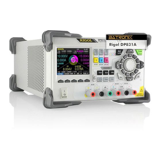
Rigol DP800 Series Calibration Manual
Programmable linear dc power supply
Hide thumbs
Also See for DP800 Series:
- Programming manual (205 pages) ,
- User manual (112 pages) ,
- Quick manual (29 pages)
Summary of Contents for Rigol DP800 Series
- Page 1 RIGOL Calibration Guide DP800 Series Programmable Linear DC Power Supply Jan. 2014 RIGOL Technologies, Inc.
- Page 3 Notices RIGOL products are protected by patent law in and outside of P.R.C. RIGOL reserves the right to modify or change parts of or all the specifications and pricing policies at company’s sole decision. Information in this publication replaces all previously corresponding material.
-
Page 4: Document Overview
RIGOL Document Overview This manual gives a detailed introduction of the calibration notices and calibration process of DP800. Subjects in this Manual Chapter 1 Calibration Notices This chapter gives a detailed introduction of the recommended calibration interval, calibration safety, the method to stop the calibration and the related information, the method to acquire the calibration service, the recommended test devices and the notices during the test. - Page 5 RIGOL Content Conventions in this Manual DP800 series programmable linear DC power supply includes the following models. Unless specified otherwise in this manual, DP831A is taken as an example to illustrate the calibration notices and calibration process of DP800 series.
-
Page 6: Table Of Contents
RIGOL Contents Contents Guaranty and Declaration ................ I Document Overview ................II Chapter 1 Calibration Notices ............1-1 Calibration Interval ................1-1 Calibration Safety................... 1-1 To Stop the Calibration ................1-1 To Acquire the Calibration Service ............1-2 Recommended Test Devices ..............1-2 Test Notices .................. -
Page 7: Chapter 1 Calibration Notices
Chapter 1 Calibration Notices RIGOL Chapter 1 Calibration Notices Calibration Interval Regular calibration can ensure the performance specifications of DP800. You are recommended to calibrate the instrument at a one-year calibration interval. Please perform regular calibration if higher accuracy is required. -
Page 8: To Acquire The Calibration Service
RIGOL Chapter 1 Calibration Notices To Acquire the Calibration Service RIGOL does not recommend manual calibration by users. If calibration is required, please contact RIGOL customer service department or the local distributor. Recommended Test Devices It is recommended that you use the test devices listed in the table below or other test devices whose performance specifications satisfy the “Performance Requirement”... -
Page 9: Chapter 2 Calibration Process
Chapter 2 Calibration Process RIGOL Chapter 2 Calibration Process Warm the DP800 up for at least 30 minutes. Press Utility Test/Cal ManualCal, input the correct password using the numeric keyboard. Then, press OK to enter the calibration interface as shown in the figure below (take DP831A as an example). - Page 10 RIGOL Chapter 2 Calibration Process 3. Meas Val Press this softkey after selecting a calibration point. The Meas Value column of the corresponding point becomes editable (the reference voltage or current of the corresponding point is displayed on the interface) and Input Val becomes available.
-
Page 11: Dac Calibration
(take CH1 as an example; the calibration method is also applicable to CH2 and CH3) of DP800 with the voltage input terminals of the digital multimeter using the test leads as shown in the figure below. DP800 Series ◎ ◎ ◎ ◎... - Page 12 RIGOL Chapter 2 Calibration Process Note: The differences between the V DAC calibration steps of the channels which support the Sense function (CH2 of DP821A and DP811A) and the above calibration steps are as shown below. The following operations should be performed before the first step (connect the channel output terminals of DP800 with the voltage input terminals of the digital multimeter).
-
Page 13: Adc Calibration
Chapter 2 Calibration Process RIGOL V ADC Calibration Make sure that DP800 has been warmed up for at least 30 minutes. Connect the channel output terminals (take CH1 as an example; the calibration method is also applicable to CH2 and CH3) of DP800 with the voltage input terminals of the digital multimeter using the test leads as shown in Figure 2-2. - Page 14 RIGOL Chapter 2 Calibration Process Short-circuit the (-) terminal of the output terminals with the (S-) terminal of the Sense terminals of the corresponding channel using the short circuitor. Turn on the Sense function of the corresponding channel before the second step (enable the channel output).
-
Page 15: I Dac Calibration
(take CH1 as an example; the calibration method is also applicable to CH2 and CH3) of DP800 with the current input terminals of the digital multimeter using the test leads as shown in the figure below. DP800 Series ◎ ◎ ◎ ◎... -
Page 16: I Adc Calibration
RIGOL Chapter 2 Calibration Process I ADC Calibration Make sure that DP800 has been warmed up for at least 30 minutes. Connect the channel output terminals (take CH1 as an example; the calibration method is also applicable to CH2 and CH3) of DP800 with the current input terminals of the digital multimeter using the test leads as shown in Figure 2-3.


Need help?
Do you have a question about the DP800 Series and is the answer not in the manual?
Questions and answers