Table of Contents
Advertisement
Quick Links
Advertisement
Table of Contents

Related Manuals for Rigol DP2000 Series


Summary of Contents for Rigol DP2000 Series
- Page 2 • RIGOL products are covered by P.R.C. and foreign patents, issued and pending. • RIGOL reserves the right to modify or change parts of or all the specifications and pricing policies at the company's sole decision. • Information in this publication replaces all previously released materials.
-
Page 3: Table Of Contents
Using the Built-in Help System..................Using the Protection Function....................Constant Voltage Output......................27 Constant Current Output......................30 Series/Parallel Connections....................31 Series Connections......................Parallel Connections......................34 Function..........................37 Setting Arb Properties......................38 Editor..........................40 9.2.1 Inserting a Single Point................... Copyright ©RIGOL TECHNOLOGIES CO., LTD. All rights reserved. DP2000 User Guide... - Page 4 Track Mode........................13.2.2 Safe Mode........................70 13.2.3 Sampling Mode......................70 13.2.4 Output Connection....................13.2.5 Output Off Mode.......................71 13.2.6 Current Sampling Rate.....................72 13.3 Interface Settings.......................72 13.3.1 LXI Status........................13.3.2 Setting........................74 13.3.3 RS232 Setting......................76 Copyright ©RIGOL TECHNOLOGIES CO., LTD. All rights reserved. DP2000 User Guide...
- Page 5 15.2 Remote Control via LAN....................85 15.3 Remote Control via GPIB (Optional)................86 15.4 Remote Control via RS232....................87 Troubleshooting.........................90 Specifications..........................92 Appendix............................18.1 Appendix A: Accessories and Options................97 18.2 Appendix B: Warranty.......................97 Copyright ©RIGOL TECHNOLOGIES CO., LTD. All rights reserved. DP2000 User Guide...
- Page 6 Figure 10.6 Log Setting Interface ..................53 Figure 11.1 Digital Port Connections ................55 Figure 11.2 Trigger Setting Interface ................Figure 11.3 Trigger Input Setting Interface ..............56 Figure 11.4 Trigger Output Setting Interface ..............58 Copyright ©RIGOL TECHNOLOGIES CO., LTD. All rights reserved. DP2000 User Guide...
- Page 7 Figure 13.12 USB Configuration Interface ..............Figure 13.13 GPIB Configuration Interface ..............Figure 13.14 Option Settings Interface ................Figure 15.1 Search for the Available Device ..............Figure 15.2 Confirm the Available Device ............... Copyright ©RIGOL TECHNOLOGIES CO., LTD. All rights reserved. DP2000 User Guide...
- Page 8 Table 4.3 AC input power specifications (including AC selector setting) .....19 Table 4.4 Fuse Rating ......................22 Table 9.1 Arb Parameters (Template) ................Table 13.1 Factory Default Values ..................Table 13.2 RS232 Pin Definition ..................77 Copyright ©RIGOL TECHNOLOGIES CO., LTD. All rights reserved. DP2000 User Guide...
-
Page 9: Safety Requirement
• Do Not Operate With Suspected Failures. If you suspect damage occurs to the instrument, have it inspected by RIGOL authorized personnel before further operations. Any maintenance, adjustment or Copyright ©RIGOL TECHNOLOGIES CO., LTD. All rights reserved. DP2000 User Guide... - Page 10 Safety Requirement replacement especially to circuits or accessories must be performed by RIGOL authorized personnel. • Keep Well Ventilation. Inadequate ventilation may cause an increase of temperature in the instrument, which would cause damage to the instrument. So please keep the instrument well ventilated and inspect the air outlet and the fan regularly.
-
Page 11: Safety Notices And Symbols
Voltage Terminal Measurement Category Measurement Category This instrument can make measurements in Measurement Category I. WARNING This instrument can only be used for measurements within its specified measurement categories. Copyright ©RIGOL TECHNOLOGIES CO., LTD. All rights reserved. DP2000 User Guide... -
Page 12: Ventilation Requirement
So please keep the instrument well ventilated and inspect the air outlet and the fan regularly. Working Environment Temperature Operating: 0℃ to +40℃ Non-operating: -40℃ to +60℃ Humidity • Operating: Below +30℃: ≤90% RH (without condensation) Copyright ©RIGOL TECHNOLOGIES CO., LTD. All rights reserved. DP2000 User Guide... - Page 13 For example, indoor environment. • Pollution Degree 3: Conductive pollution or dry nonconductive pollution that becomes conductive due to condensation occurs. To be found in industrial Copyright ©RIGOL TECHNOLOGIES CO., LTD. All rights reserved. DP2000 User Guide...
-
Page 14: Care And Cleaning
Please contact your local authorities for disposal or recycling information. Copyright ©RIGOL TECHNOLOGIES CO., LTD. All rights reserved. DP2000 User Guide... - Page 15 Safety Requirement https://int.rigol.com/services/services/declaration You can click on the following link to download the latest version of the RoHS&WEEE certification file. Copyright ©RIGOL TECHNOLOGIES CO., LTD. All rights reserved. DP2000 User Guide...
-
Page 16: Product Overview
6 V/10 A, both CH1 and CH2 switch to 32 V/2 A from 32 V/3 A. Note[2]: The GPIB and RS232 share the same port. The optional GPIB interface can be installed in place of the RS232 interface. Copyright ©RIGOL TECHNOLOGIES CO., LTD. All rights reserved. DP2000 User Guide... -
Page 17: Document Overview
This manual gives you a quick overview of the front and rear panel, user interface, and basic operation methods of DP2000 Series Programmable DC Power Supply. http:// For the latest version of this manual, download it from the official website of RIGOL ( www.rigol.com Publication Number... - Page 18 : 32 V/2 A, 32 V/2 A, 6 V/10 A (optional) Note[1]: The CH3 of DP2000 series has two ranges: 6 V/5 A and 6 V/10 A (optional). When it switches to 6 V/10 A, both CH1 and CH2 switch to 32 V/2 A.
-
Page 19: Quick Start
The consigner or carrier shall be liable for the damage to the instrument resulting from shipment. RIGOL would not be responsible for free maintenance/rework or replacement of the instrument. 2. Inspect the instrument In case of any mechanical damage,missing parts, or failure in passing the electrical and mechanical tests, contact your RIGOL sales representative. -
Page 20: Appearance And Dimensions
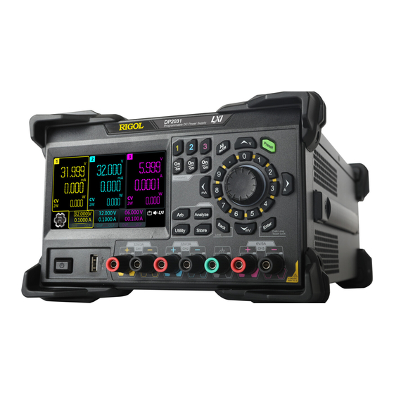
Figure 4.1 Front View Figure 4.2 Side View Front Panel This section introduces the front panel of the DP2000 series by taking DP2031 (as shown in the figure below) as an example. The model-specific features will be introduced in particular. -
Page 21: Figure 4.3 Dp2000 Front Panel
Press this key and a prompt message will be displayed asking whether to turn all channels on. Tap OK to turn all channels on. Pressing this key again can turn all channels off. Copyright ©RIGOL TECHNOLOGIES CO., LTD. All rights reserved. DP2000 User Guide... - Page 22 4. Preset Key Press the key to restore the instrument to factory default (refer to Factory Default Values 5. Enter Key Press the key to confirm your value. Copyright ©RIGOL TECHNOLOGIES CO., LTD. All rights reserved. DP2000 User Guide...
-
Page 23: Figure 4.4 Dp2000 Output Terminals
Arb file, calibration file, option installation verification file, and bitmap file. You are allowed to store a file to internal or external memory and also recall the file from internal or external memory. 9. USB HOST Port Copyright ©RIGOL TECHNOLOGIES CO., LTD. All rights reserved. DP2000 User Guide... -
Page 24: Rear Panel
10. Power Switch Key Press this key to power on or off the instrument. Rear Panel This section introduces the rear panel of DP2000 series by taking DP2031 (as shown in the figure below) as an example. Figure 4.5 DP2000 Rear Panel Table 4.1 DP2000 Rear Panel Description... -
Page 25: User Interface
Available for RS232 or GPIB interface RS232/GPIB port (optional) Note[1]: DP2000 series provides RS232 (standard) and GPIB (optional). Sharing a physical port, those two interfaces cannot be used concurrently. User Interface > Display to assess the interface as shown in the figure below. This section introduces the meter-view display of the power supply. -
Page 26: Figure 4.6 User Interface
Sense connection 4W indicates that 4-wire sensing (remote sensing) measurement is in use. 2W indicates that 2-wire sensing (local sensing) measurement is in use. Actual output power Navigation icon Copyright ©RIGOL TECHNOLOGIES CO., LTD. All rights reserved. DP2000 User Guide... -
Page 27: Connecting To Power
: the beeper is turned on. : downloading the firmware upgrade file. Connecting to Power DP2000 series power supply supports various AC power inputs. The AC selector setting on the rear panel differs when input power is different, as shown in the table below. - Page 28 Please connect the instrument to AC power using the power cord provided in the accessories. WARNING To avoid electric shock, please make sure that the instrument is correctly grounded. Copyright ©RIGOL TECHNOLOGIES CO., LTD. All rights reserved. DP2000 User Guide...
-
Page 29: Power-On Inspection
Turn off AC power before making front panel connections. All wires and straps must be properly connected to prevent currents from damaging the loads. Rear Outputs Connections Insert the connector plug into the rear terminal. Secure the connector by tightening the locking screws. Copyright ©RIGOL TECHNOLOGIES CO., LTD. All rights reserved. DP2000 User Guide... -
Page 30: Replacing The Fuse
1. Power off the instrument and remove the power cord. 2. Insert a small straight screwdriver into the slot at the power socket and pry out the fuse holder gently. Copyright ©RIGOL TECHNOLOGIES CO., LTD. All rights reserved. DP2000 User Guide... -
Page 31: Using The Built-In Help System
> Help to enter the help interface as shown in the figure below. The built-in help system can help you learn about the instrument, obtain a list of help topics, and update instrument firmware. Figure 4.7 Help Interface Copyright ©RIGOL TECHNOLOGIES CO., LTD. All rights reserved. DP2000 User Guide... - Page 32 Tap Others to enter the interface in which you can obtain the following help topics: • View the last displayed message • View remote command error queue • Contact RIGOL Technical Support • Open source statement Copyright ©RIGOL TECHNOLOGIES CO., LTD. All rights reserved. DP2000 User Guide...
-
Page 33: Using The Protection Function
Press the knob again to disable the editing mode. Copyright ©RIGOL TECHNOLOGIES CO., LTD. All rights reserved. DP2000 User Guide... - Page 34 You can also set the OCP delay period by sending :OUTPut:OCP:DELAy [CH1|CH2| CH3], {<value>|MINimum|MAXimum} SCPI command (refer to the series Programming Guide ). The delay can be programmed from 0 to 1000 ms. Copyright ©RIGOL TECHNOLOGIES CO., LTD. All rights reserved. DP2000 User Guide...
-
Page 35: Constant Voltage Output
Method 2: You can also use the touch screen function to set the voltage. Copyright ©RIGOL TECHNOLOGIES CO., LTD. All rights reserved. DP2000 User Guide... - Page 36 6. Enable the output Pressing the channel on/off key can turn on the respective channel output. When a channel is turned on, its on/off key is illuminated. Rather, when the Copyright ©RIGOL TECHNOLOGIES CO., LTD. All rights reserved. DP2000 User Guide...
- Page 37 CC mode automatically. At this time, the output current equals to the current setting value, and the output voltage can be calculated by the current times the load impedance. Copyright ©RIGOL TECHNOLOGIES CO., LTD. All rights reserved. DP2000 User Guide...
-
Page 38: Constant Current Output
CV output mode automatically. At this time, the output voltage equals to the voltage setting value, and the output current can be calculated by the voltage divided by the load impedance. Copyright ©RIGOL TECHNOLOGIES CO., LTD. All rights reserved. DP2000 User Guide... -
Page 39: Series/Parallel Connections
The output voltage and current are displayed in CH1 meter view, as is shown in the figure below. Copyright ©RIGOL TECHNOLOGIES CO., LTD. All rights reserved. DP2000 User Guide... -
Page 40: Figure 8.1 Series Output Interface
If voltage drop in the load leads is a concern, please connect the sense leads to load Sense Settings (refer to ). The connections on the rear panel in internal series mode is shown in the figure below. Copyright ©RIGOL TECHNOLOGIES CO., LTD. All rights reserved. DP2000 User Guide... -
Page 41: Figure 8.2 External Series Circuit
Figure 8.2 External Series Circuit Operation Procedures: 1. Connect the power supply to load as shown in the figure above. Pay attention to the polarity when making connections. Copyright ©RIGOL TECHNOLOGIES CO., LTD. All rights reserved. DP2000 User Guide... -
Page 42: Parallel Connections
Figure 8.3 Parallel Output Interface The figure below shows how to connect front output terminals to a single load in Output Connection internal parallel mode. Please refer to for channel connection. Copyright ©RIGOL TECHNOLOGIES CO., LTD. All rights reserved. DP2000 User Guide... - Page 43 This series power supply supports external parallel connection for multiple channels (from a single power supply or multiple power supplies). The figure below illustrates how to connect two outputs in external parallel. Copyright ©RIGOL TECHNOLOGIES CO., LTD. All rights reserved. DP2000 User Guide...
-
Page 44: Figure 8.4 External Parallel Circuit
) and turn on the output of each channel. All channels can work in CV mode or CC mode. CAUTION All the channels can work in CV or CC mode according to the actual need of the load. Copyright ©RIGOL TECHNOLOGIES CO., LTD. All rights reserved. DP2000 User Guide... -
Page 45: Arb Function
Arb Function Arb Function The Arbitrary function of DP2000 series power supply enables you to generate freely programmable waveforms which can be reproduced within the limit settings for voltage and current. You can set the repetition cycle for the arbitrary waveform as well as the output voltage/current and time for each group of data. -
Page 46: Setting Arb Properties
Off: The output of the selected channel is turned off automatically after the output sequence completes. • Last: The instrument remains at the last voltage and current values after the output sequence completes. Copyright ©RIGOL TECHNOLOGIES CO., LTD. All rights reserved. DP2000 User Guide... - Page 47 When the run mode is set to “Single”, tap Run(Sgl) and then tap output a single group of data. Copyright ©RIGOL TECHNOLOGIES CO., LTD. All rights reserved. DP2000 User Guide...
-
Page 48: Arb Editor
As shown in the figure above, the table displays 4 groups of data per page. You can view and edit data of other groups in the following ways. • Tap Prev or Next to turn pages. Copyright ©RIGOL TECHNOLOGIES CO., LTD. All rights reserved. DP2000 User Guide... -
Page 49: Inserting A Single Point
Tap Templet to open the template editing menu, as shown in the figure below. You can edit and create your desired waveform in the following steps. Figure 9.4 Template Editing Menu 1. Select Waveform Templates Copyright ©RIGOL TECHNOLOGIES CO., LTD. All rights reserved. DP2000 User Guide... - Page 50 (P) in a complete period. Setting the symmetry (Sym) creates the Ramp waveform. The rising edge of the Ramp waveform has int (P*Sym) points and the falling edge has P-int (P*Sym) points. Copyright ©RIGOL TECHNOLOGIES CO., LTD. All rights reserved. DP2000 User Guide...
- Page 51 (MAX-MIN )/int(N/2) and then drops to MIN by the same step size. When N is even, the waveform rises from MIN to MAX by step size of (MAX- Copyright ©RIGOL TECHNOLOGIES CO., LTD. All rights reserved. DP2000 User Guide...
- Page 52 The available range depends on the rise/fall index currently set. The larger the rise/fall index, the wider the Copyright ©RIGOL TECHNOLOGIES CO., LTD. All rights reserved. DP2000 User Guide...
-
Page 53: Table 9.1 Arb Parameters (Template)
Ramp Max, Min, Period, Interval, Groups, Symmetry, Invert On/Off Stair Up Max, Min, Period, Steps, Groups Stair Dn Max, Min, Period, Steps, Groups StairUpDn Max, Min, Period, Steps, Groups Copyright ©RIGOL TECHNOLOGIES CO., LTD. All rights reserved. DP2000 User Guide... - Page 54 When the template currently selected is Ramp, you can set the symmetry (namely the ratio of the duration of the rising edge within a period to the whole period). The range is from 0% to 100%. - Steps Copyright ©RIGOL TECHNOLOGIES CO., LTD. All rights reserved. DP2000 User Guide...
-
Page 55: Delete
Read. A prompt message “Arb file is imported successfully” is displayed and the instrument goes back to the Arb main interface. You can edit the imported Arb file. Copyright ©RIGOL TECHNOLOGIES CO., LTD. All rights reserved. DP2000 User Guide... -
Page 56: Enabling The Arb Output
When the generator is turned on, you need to turn on the corresponding channel to ensure valid waveform output. • When the output is initiated, all the Arb settings and parameters cannot be configured. Copyright ©RIGOL TECHNOLOGIES CO., LTD. All rights reserved. DP2000 User Guide... -
Page 57: Analyzer
Analyzer Analyzer DP2000 series power supply provides the Analyzer function for you to analyze the quality of output signals. Available analysis functions for the 3 channels include common analysis, pulse current analysis (only for CH1 and CH2), and data logging. -
Page 58: Selecting Analysis Object
Then tap OK to go back to the analyzer main interface. Tap Run and the instrument will execute analysis based on the your selections. Figure 10.3 Analysis Object Setting Menu Copyright ©RIGOL TECHNOLOGIES CO., LTD. All rights reserved. DP2000 User Guide... -
Page 59: Selecting Statistical Method
When the data is out of the screen, it will be compressed and displayed proportionally in the trend plot. Then, real-time data will be redrawn from left to right. Copyright ©RIGOL TECHNOLOGIES CO., LTD. All rights reserved. DP2000 User Guide... -
Page 60: Pulse Current Analysis
3. Then tap OK to return to the Analyzer main interface. Tap Run and the instrument will execute analysis based on your selections. The analysis interface is shown in the figure below. The analysis results are at the lower part of the interface. Copyright ©RIGOL TECHNOLOGIES CO., LTD. All rights reserved. DP2000 User Guide... -
Page 61: Data Logging
Tap Save to input field to access the Store and Recall interface. Select the desired storage path and then tap Save. Set the filename in the pop-up filename input field. The data is stored to a file with .ROF extension. Copyright ©RIGOL TECHNOLOGIES CO., LTD. All rights reserved. DP2000 User Guide... -
Page 62: Print Screen
For example, the second screen image is named “Analyzer1.BMP”. 10.5 Label Control Tap label Control in the Analyzer main interface to hide or display the labels of analysis objects. Copyright ©RIGOL TECHNOLOGIES CO., LTD. All rights reserved. DP2000 User Guide... -
Page 63: Trigger
Trigger Trigger DP2000 series power supply supports trigger input and trigger output via the rear- panel Digital I/O interface. • Trigger Input: The data lines of the digital I/O interface receive external trigger signal. The source under control (namely the selected output channel) turns on/off the output or inverts the output state when the preset trigger condition is met. -
Page 64: Trigger Input
> Trigger at the lower-left of the screen. Then select Trigger Input to open the trigger input setting interface, as is shown in the figure below. Figure 11.3 Trigger Input Setting Interface Copyright ©RIGOL TECHNOLOGIES CO., LTD. All rights reserved. DP2000 User Guide... -
Page 65: Trigger Output
The specified data line outputs a high/low level signal when the control source turns on the output. > Trigger and select Trigger Output to access the trigger output setting interface, as shown in the figure below. Copyright ©RIGOL TECHNOLOGIES CO., LTD. All rights reserved. DP2000 User Guide... -
Page 66: Figure 11.4 Trigger Output Setting Interface
High Level: The selected data line outputs 3.3 V high level when the control source is turned on. • Low Level: The selected data line outputs low level signal (CMOS level) when the control source is turned on. Copyright ©RIGOL TECHNOLOGIES CO., LTD. All rights reserved. DP2000 User Guide... -
Page 67: Store And Recall
Do not copy unsupported file type to C disk, or a prompt message “Filetype not supported.” will be displayed. The C disk supports file locking. You can lock/unlock files via the SCPI command :MEMory:LOCK <name>,<bool>. A lock icon will appear at the upper- Copyright ©RIGOL TECHNOLOGIES CO., LTD. All rights reserved. DP2000 User Guide... -
Page 68: Select
2. Tap Save to pop up the filename setting interface, as is shown in the figure below. 3. Enter your desired filename in the “FileName” input field. Then tap complete the entry and save the file, or tap to cancel the operation. This Copyright ©RIGOL TECHNOLOGIES CO., LTD. All rights reserved. DP2000 User Guide... -
Page 69: Read
2. Tap Delete, and a prompt message “Delete selected files?” is displayed. Tap Yes to delete the file. You can also click or tap SafeClear in the C disk to delete all files (including locked files) in it. Copyright ©RIGOL TECHNOLOGIES CO., LTD. All rights reserved. DP2000 User Guide... -
Page 70: Copy And Paste
C disk has 2GB memory size. When it is running out of space, a prompt message “Low disk space.” will be displayed. • The file copied to C disk cannot be larger than 2MB. • Unsupported file type cannot be copied to C disk. Copyright ©RIGOL TECHNOLOGIES CO., LTD. All rights reserved. DP2000 User Guide... -
Page 71: Utility
Set the system parameters, such as Preset key, power-on settings, and beeper. • Display Options Set the brightness and system language. • Sense Settings Turn on/off the Sense function for the three channels respectively. Copyright ©RIGOL TECHNOLOGIES CO., LTD. All rights reserved. DP2000 User Guide... -
Page 72: Instrument Settings
Tap Preset to define the function of the front-panel “Preset” key. You can select “Default”. Press on the front panel and a prompt message “Restore the instrument to factory default settings?” is displayed. Tap Yes to restore to factory default. Copyright ©RIGOL TECHNOLOGIES CO., LTD. All rights reserved. DP2000 User Guide... -
Page 73: Table 13.1 Factory Default Values
(Sine, Ramp, StairUp, StairDn, 50 s StairUpDn) Invert Positive Pulse Width 25 s Symmetry Steps Analyzer Display Empty Object Channel Method RT Plot Channel (Pulse Current Analysis) Positive/Negative Pulse Positive Pulse Copyright ©RIGOL TECHNOLOGIES CO., LTD. All rights reserved. DP2000 User Guide... - Page 74 CH-Off Mode Channel Connection Independent Sampling Auto Current Sampling Rate 3.75 kSPS DHCP AUTO MANUAL Bit Rate 9600 Data Bit Parity None Stop Bit GPIB Address Store Current Directory Copyright ©RIGOL TECHNOLOGIES CO., LTD. All rights reserved. DP2000 User Guide...
-
Page 75: Display Options
The following figures illustrate load connections using 2-wire sensing and remote sensing. Copyright ©RIGOL TECHNOLOGIES CO., LTD. All rights reserved. DP2000 User Guide... -
Page 76: Figure 13.4 Rear Panel Connections
3. After that, press >System>Sense Settings or tap >Utility>System>Sense Settings to enter the interface as shown in the figure below. Figure 13.5 Sense Settings Interface Copyright ©RIGOL TECHNOLOGIES CO., LTD. All rights reserved. DP2000 User Guide... -
Page 77: Output Settings
CH1 and CH2. You can enable or disable the track mode for those two channels. Tap the Tracking on/off button to toggle between ON and OFF to enable or disable the track mode. Copyright ©RIGOL TECHNOLOGIES CO., LTD. All rights reserved. DP2000 User Guide... -
Page 78: Safe Mode
When the output voltage exceeds 60 V in series connection, please do not touch the output terminals. 13.2.3 Sampling Mode DP2000 series power supply provides three current sampling modes for CH1 and CH2. You can select “High Curr”, “Low Curr”, or “AUTO”. The default setting is “AUTO”. •... -
Page 79: Output Connection
IMM: Clears the circuit immediately and turn off outputs when channels are off. • Delay: Uses the turn-off delay when channels are off. When "IMM" is selected, the voltage fall time is not guaranteed. Copyright ©RIGOL TECHNOLOGIES CO., LTD. All rights reserved. DP2000 User Guide... -
Page 80: Current Sampling Rate
Utility 13.2.6 Current Sampling Rate DP2000 series power supply provides three preset current sampling rate options for CH1 and CH2. Tap CurrSampRate drop-down button to select 3.75K SPS, 7.5K SPS, or 29 SPS. 13.3 Interface Settings DP2000 series supports remote interface communication over interfaces including USB, LAN, RS232, and GPIB (optional). -
Page 81: Figure 13.8 Lxi Status Interface
It displays the IP configuration information: IP not obtained, DHCP, or AUTO. LXI Setting You can set the IP source in interface. • IP address It displays the IP address of the instrument. Copyright ©RIGOL TECHNOLOGIES CO., LTD. All rights reserved. DP2000 User Guide... -
Page 82: Lxi Setting
In the Interface Settings menu, tap LXI Config to access the menu as shown in the figure below. You can tap LXI Config again to collapse the current menu to revert to the Interface Settings menu. Figure 13.9 LXI Settings Menu Copyright ©RIGOL TECHNOLOGIES CO., LTD. All rights reserved. DP2000 User Guide... - Page 83 This setting is non-volatile. The instrument will load your gateway address automatically at the next power-on if “DHCP” and “Auto IP” are set to "OFF". • Subnet Mask Copyright ©RIGOL TECHNOLOGIES CO., LTD. All rights reserved. DP2000 User Guide...
-
Page 84: Rs232 Setting
Connect the RS232 interface to your PC or data terminal equipment (DTE) using RS232 cable and set the interface parameters (baud rate, parity bit, etc.) that match the PC or terminal equipment. Then, you can control the instrument remotely. Copyright ©RIGOL TECHNOLOGIES CO., LTD. All rights reserved. DP2000 User Guide... -
Page 85: Figure 13.10 Rs232 Interface
In the Interface Settings menu, tap RS232 Config to access the menu as shown in the figure below. You can tap RS232 Config again to collapse the current menu to revert to the Interface Settings menu. Copyright ©RIGOL TECHNOLOGIES CO., LTD. All rights reserved. DP2000 User Guide... -
Page 86: Usb Configuration
In the Interface Settings menu, tap USB Config to enter the interface as shown in the figure below. The interface displays the USB information. You can tap USB Config again to collapse the current menu to revert to the Interface Settings menu. Copyright ©RIGOL TECHNOLOGIES CO., LTD. All rights reserved. DP2000 User Guide... -
Page 87: Gpib Configuration
The value can be any integer ranging from 0 to 30, and the default is 2. This setting is non-volatile; it will not be changed by factory reset. Copyright ©RIGOL TECHNOLOGIES CO., LTD. All rights reserved. DP2000 User Guide... -
Page 88: Option Settings
“.lic”. After you purchase an option, you will obtain a key (used for obtaining the desired option license). Please install the option following the steps below. 1. Obtain an option license Copyright ©RIGOL TECHNOLOGIES CO., LTD. All rights reserved. DP2000 User Guide... - Page 89 Utility http://www.rigol.com a. Log in to the RIGOL official website ( ), and click SERVICE CENTRE > License Activation to enter the software license registration interface. b. In the software license registration interface, enter the correct key, serial number (tap >...
-
Page 90: Locking/Unlocking The Front Panel
Nth line is blank. At this point, you can execute locking /unlocking operations N-1 times by reading the file in the instrument. Operation Procedures: Copyright ©RIGOL TECHNOLOGIES CO., LTD. All rights reserved. DP2000 User Guide... - Page 91 Program and send command to lock or unlock the specified key. Set up communication between the instrument and PC. Use a programming language (e.g. LabVIEW, C#) to program and send command. Copyright ©RIGOL TECHNOLOGIES CO., LTD. All rights reserved. DP2000 User Guide...
-
Page 92: Remote Control
• PC Software You can use the PC software to send commands to control the instrument remotely. Ultra Sigma of RIGOL is recommended. You can log in to RIGOL official http://www.rigol.com website ( ) to download the software. -
Page 93: Remote Control Via Usb
PC via the USB interface. You can also click USB-TMC to search for the resource. 3. View the device resource The resources found will appear under the "RIGOL Online Resource" directory, and the model number and USB interface information of the instrument will also be displayed. -
Page 94: Remote Control Via Gpib (Optional)
IP address that you input is correct, or use the auto search method to add the instrument resource. 4. View the device resource The resources found will appear under the "RIGOL Online Resource" directory. 5. Control the instrument remotely Right-click the device resource name and select “SCPI Panel Control” to open the remote command control panel. -
Page 95: Remote Control Via Rs232
5. View the device resource Click OK to go back to the main interface of Ultra Sigma. The searched instrument resource will be displayed under the directory of "RIGOL Online Resource". 6. Control the instrument remotely Right-click the device resource name and select “SCPI Panel Control” to open the remote command control panel. - Page 96 PC via the RS232 cable and whether the RS232 parameters of the software match with the current settings of the instrument. 4. View the device resource The resources found will appear under the "RIGOL Online Resource" directory. 5. Control the instrument remotely Copyright ©RIGOL TECHNOLOGIES CO., LTD. All rights reserved.
- Page 97 Remote Control Right-click the device resource name and select “SCPI Panel Control” to open the remote command control panel. Then you can send commands and read data through the panel. Copyright ©RIGOL TECHNOLOGIES CO., LTD. All rights reserved. DP2000 User Guide...
-
Page 98: Troubleshooting
The following failures may occur during the use of the instrument. Please first try to handle the problem according to the following methods; if the problem remains unsolved, please contact RIGOL and provide the device information of your instrument (by tapping >... - Page 99 USB storage device. c. Restart the instrument and insert the USB storage device to check. d. If the USB storage device still cannot work normally, please contact RIGOL. Copyright ©RIGOL TECHNOLOGIES CO., LTD. All rights reserved.
-
Page 100: Specifications
Load regulation rate, ± (% of output + offset) Voltage <0.01%+2 mV Current <0.01%+250 μA Line Regulation Rate Line regulation rate, ± (% of output + offset) Voltage <0.01%+2 mV Copyright ©RIGOL TECHNOLOGIES CO., LTD. All rights reserved. DP2000 User Guide... - Page 101 Less than 50 μs of time to recover to within the ±15 mV settling band following a load change from 50% to 100% or from 100% to 50% of full load. Copyright ©RIGOL TECHNOLOGIES CO., LTD. All rights reserved. DP2000 User Guide...
- Page 102 0.01%+3 mA Mechanical Characteristics Mechanical characteristics Dimension 239 mm (W) x 157 mm (H) x 419 mm (D) Weight 9.95 kg Rack mount kit Three rack-units (3U), 1/2-rack form factor Copyright ©RIGOL TECHNOLOGIES CO., LTD. All rights reserved. DP2000 User Guide...
- Page 103 Cooling Method Fan cooling Operating Temperature 0°C to +40°C Storage Temperature -40°C to +60°C Humidity 5% to 80% relative humidity Altitude Below 1500 meters IP Rating IP20 Pollution Degree Copyright ©RIGOL TECHNOLOGIES CO., LTD. All rights reserved. DP2000 User Guide...
- Page 104 Note[3]: The low range current mode is applicable to measurement of current lower than 10 mA. Note[4]: the time required for the output to change accordingly after receiving the APPLy and SOURce commands. Copyright ©RIGOL TECHNOLOGIES CO., LTD. All rights reserved. DP2000 User Guide...
-
Page 105: Appendix
If a product proves defective within the warranty period, RIGOL guarantees free replacement or repair for the defective product. To get repair service, please contact your nearest RIGOL sales or service office. Copyright ©RIGOL TECHNOLOGIES CO., LTD. All rights reserved. DP2000 User Guide... - Page 106 There is no implied warranty of merchantability or fitness for a particular purpose. Under no circumstances shall RIGOL be liable for any consequential, indirect, ensuing, or special damages for any breach of warranty in any case.
Need help?
Do you have a question about the DP2000 Series and is the answer not in the manual?
Questions and answers