Table of Contents
Advertisement
Quick Links
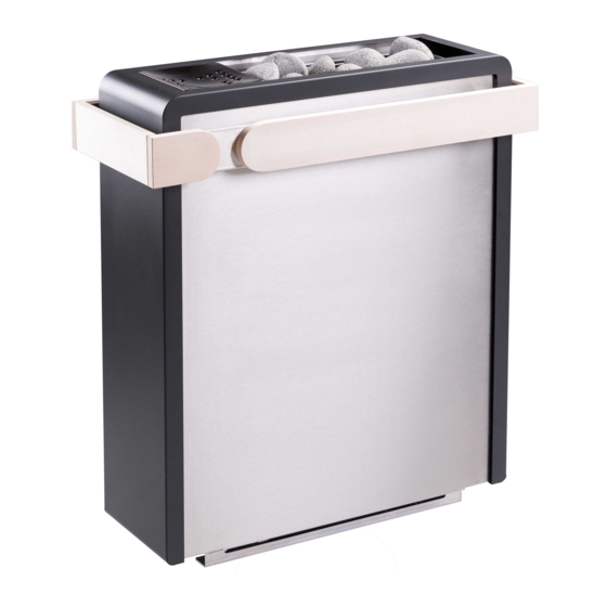
Sauna heater
Concept R mini combi
CP-RMC-35 / 1-041-405: Concept R mini combi 3.5 kW
CP-RMC-45 / 1-041-406: Concept R mini combi 4.5 kW
CP-RMC-60 / 1-041-407: Concept R mini combi 6.0 kW
CP-RMC-75 / 1-041-408: Concept R mini combi 7.5 kW
INSTRUCTIONS FOR INSTALLATION AND USE
English
EN
Version 07/18
Ident. no. CP-RMC-MA
Advertisement
Table of Contents

Related Manuals for Sentiotec Concept R mini combi CP-RMC-35


Summary of Contents for Sentiotec Concept R mini combi CP-RMC-35
- Page 1 Sauna heater Concept R mini combi CP-RMC-35 / 1-041-405: Concept R mini combi 3.5 kW CP-RMC-45 / 1-041-406: Concept R mini combi 4.5 kW CP-RMC-60 / 1-041-407: Concept R mini combi 6.0 kW CP-RMC-75 / 1-041-408: Concept R mini combi 7.5 kW INSTRUCTIONS FOR INSTALLATION AND USE English Version 07/18...
-
Page 2: Table Of Contents
Table of Contents 1. About this instruction manual 2. Important information for your safety 2.1. Intended use 2.2. Safety information for the installer 2.3. Safety information for the user 3. Product description 3.1. Scope of delivery 3.2. Accessories 3.3. Product functions 4. - Page 3 6. Operation 6.1. Finnish sauna mode 6.2. Combi mode 7. Maintenance 7.1. Extended periods of non-use 7.2. Cleaning the sauna heater 7.3. Changing the sauna stones 7.4. Cleaning the evaporator tank 7.5. Cleaning the ceramic bowl 7.6. Descaling the evaporator tank 8.
-
Page 4: About This Instruction Manual
These installation and operating instructions can also be found in the downloads section of our website: www.sentiotec.com/downloads. Symbols used for warning notices In these instructions for installation and use, a warning notice located next to an activity indicates that this activity poses a risk. -
Page 5: Important Information For Your Safety
Instructions for installation and use p. 5/34 2. Important information for your safety The Concept R mini combi sauna heater has been produced in ac- cordance with the applicable safety rules and regulations. However, hazards may occur during use. Therefore adhere to the following chapters. -
Page 6: Safety Information For The Installer
Instructions for installation and use p. 6/34 2.2. Safety information for the installer Installing and connecting the sauna heater may only be performed when the power supply is disconnected. A fully disconnecting all-pole isolating device compliant with Always use silicone cables that are heat-resistant up to 150 °C to connect the sauna heater. -
Page 7: Safety Information For The User
Instructions for installation and use p. 7/34 2.3. Safety information for the user The device must not be used by children under 8 years old. The device may only be used by children over 8 years old, by persons with limited psychological, sensory or mental capabili- ties or by persons with lack of experience/knowledge under the following conditions: –... - Page 8 Instructions for installation and use p. 8/34 Never touch the sauna heater while it is operating. The surfaces of the sauna heater and sauna stones become extremely hot. the evaporator tank each time before starting combi mode. If the overheating protection has switched off evaporator heating, or if your sauna control unit reports a lack of water, allow the evaporator to cool down BEFORE you pour water into the evaporator tank.
-
Page 9: Product Description
Instructions for installation and use p. 9/34 3. Product description 3.1. Scope of delivery Sauna heater Instructions for installation and use 3.2. Accessories Accessories Item number Set of brackets for the Concept R mini combi CP-RMC-HSR / 1-041-410 heater railing Wood railing for Concept R mini combi, lime wood CP-RMC-L / 1-041-412 Wood railing for Concept R mini combi, walnut... -
Page 10: Installation And Connection
Installation instructions, for professionals only p. 10/34 4. Installation and connection Take the following points into account when positioning and connecting the sauna heater: WARNING! Danger of electric shock The sauna heater may only be installed and connected when the power supply is disconnected. -
Page 11: Safety Intervals
Installation instructions, for professionals only p. 11/34 4.2. Safety intervals Fig. 1. Fig. 1 Safety intervals for the Concept R mini combi 3.5 kW, 4.5 kW, 6.0 kW and 7.5 kW (CP-RMC-35 / CP-RMC-45 / CR-RMC-60 / CP-RMC-75) Dimensions in mm... -
Page 12: Installation On The Cabin Wall
Installation instructions, for professionals only p. 12/34 4.3. Installation on the cabin wall Observe Fig. 1, Fig. 2, Fig. 3 and Fig. 4 (page 11, 12, 13). 1. Attach the mounting rail 1 to the wall horizontally using the wood screws supplied 2. - Page 13 Installation instructions, for professionals only p. 13/34 Fig. 3 Position of the mounting rail for Concept R mini combi Dimensions in mm Fig. 4 Securing the Concept R mini combi (mounting rail)
-
Page 14: Installation With Foot (Optional)
Installation instructions, for professionals only p. 14/34 4.4. Installation with foot (optional) Observe Fig. 1, Fig. 5, Fig. 6 (page 11, 14, 15). 1. Attach the foot 1 using the screws enclosed 2 to the bottom of the heater. Please note that the round recess is on the evaporator side. Fig. - Page 15 Installation instructions, for professionals only p. 15/34 Fig. 6 Fixing the Concept R mini combi with foot in place Fig. 7 Installing the wooden cover for the foot (optional) Place the two halves of the cover ring around the foot and press them together...
-
Page 16: Connection Diagram For 400V 3N
Installation instructions, for professionals only p. 16/34 4.5. Connection diagram for 400V 3N~ Fig. 8 Connection diagram for the Concept R mini combi 3.5 kW, 4.5 kW, 6.0 kW and 7.5 kW (CP-RMC-35 / CPC-RM-45 / CR-RMC-60 / CP-RMC-75) L1 L2 N V1W N U1W 400V 3N~... -
Page 17: Connection Diagram For 230V 1N
Installation instructions, for professionals only p. 17/34 4.6. Connection diagram for 230V 1N~ Fig. 9 Connection diagram for the Concept R mini combi 3.5 kW, 4.5 kW, 6.0 kW and 7.5 kW (CP-RMC-35 / CPC-RM-45 / CR-RMC-60 / CP-RMC-75) L1 L2 N V1W 230V 1N~ N U1W... -
Page 18: Wiring Diagrams
Installation instructions, for professionals only p. 18/34 4.7. Wiring diagrams U V W N U V W N to the control unit to the control unit CP-RMC-35 CP-RMC-45 3.5 kW 4.5 kW U V W N U V W N to the control unit to the control unit CP-RMC-75... -
Page 19: Electrical Connection
Installation instructions, for professionals only p. 19/34 4.8. Electrical connection 1. Unscrew the screws 3 with a screwdriver. 2. Remove the cover plates 1 and 2. Fig. 10 Removing the cover plates Connecting the Concept R mini combi 3.5 kW, 4.5 kW, 6.0 kW and 7.5 kW (CP-RMC-35 / CP-RMC-45 / CR-RMC-60 / CP-RMC-75) 1. -
Page 20: Installing The Heater Railing (Optional)
Installation instructions, for professionals only p. 20/34 3. Guide the evaporator cable through the feed- through 5. 4. Connect the wires of the evaporator cable to the PE – N – U1 – Wm terminals on the connector block and to the matching sauna control unit terminals. - Page 21 Installation instructions, for professionals only p. 21/34 4. Unscrew the screws C and install with them the angle railing brackets D. Depending on the preferred form of the heater railing, you will need two or four angle railing brackets. 5. Install the railing bracket E with cover A using the previously re- moved screws B.
- Page 22 Installation instructions, for professionals only p. 22/34 7. Screw the side panel F G of the bracket. If necessary, repeat this procedure on the opposite side. 8. Connect the side panel G of the bracket to the long bracket panel I with the help of the corner bracket H.
-
Page 23: Commissioning
Instructions for use for the user p. 23/34 5. Commissioning 5.1. Filling the stone container WARNING! If the sauna heater is used without sauna stones, the cabin walls will NEVER operate the sauna heater without the sauna stones. The amount of stones suited to your heater can be found in chapter 10. Tech- nical data (see page 32). - Page 24 Instructions for use for the user p. 24/34 5.3. CAUTION! Materials used during the manufacturing process will be present on the new heating elements. These evaporate when the sauna heater is odour. Breathing in the fumes or smoke can be harmful to your health. Perform the following steps when time and if the heating elements for the sauna heater have been replaced.
-
Page 25: Operation
Instructions for use for the user p. 25/34 6. Operation WARNING! Combustible objects that are placed on the heater will ignite and cause NEVER place combustible objects on the sauna heater. heater before operating it. A sauna control unit is used to operate the sauna heater. For information on how to operate the sauna control unit, read the operating instructions for the device used. -
Page 26: Combi Mode
Instructions for use for the user p. 26/34 6.2. Combi mode Both the heating system and evaporator operate in combi mode. The temperature in the sauna cabin is lower than in Finnish sauna mode (approx. 40 to 65 °C), with the relative humidity being considerably higher at 35% to approximately 70%. - Page 27 Instructions for use for the user p. 27/34 Filling the evaporator CAUTION! Risk of scalding If you pour water into the hot evaporator tank, hot steam is created. NEVER pour water into the hot evaporator tank. If the overheating protection has switched off evaporator heating, or if your sauna control unit reports a lack of water, allow the evapora- tor to cool down BEFORE you pour water into the evaporator tank.
-
Page 28: Maintenance
Instructions for use for the user p. 28/34 Using fragrances and herbs If you wish, you can put fragrances or dried herbs into the ceramic bowl. Observe the following points: Do not put fragrances directly into the evaporator tank. tor tank through the holes in the ceramic bowl. Follow the manufacturer’s instructions on the packaging of the herbs and fragrances. -
Page 29: Changing The Sauna Stones
Instructions for use for the user p. 29/34 7.3. Changing the sauna stones Sauna stones are subject to stress by the water poured on them, and by large come weak and brittle. Check the sauna stones at regular intervals and replace the stones at least once a year. -
Page 30: Cleaning The Ceramic Bowl
Instructions for use for the user p. 30/34 5. Remove the ceramic bowl and the steam funnel. 6. Clean the evaporator tank and the steam funnel with a household brush with plastic bristles. Rinse with water. 7. Put the ceramic bowl and the steam funnel back in. 7.5. -
Page 31: Problem-Solving By The Installer
Instructions for use for the user p. 31/34 9. Problem-solving by the installer Baking out of the heating rods Moisture can accumulate in the heating rods in humid ambient conditions or dur- ing long periods of non-use. This is a physical process and not a manufacturing fault. -
Page 32: Technical Data
Instructions for installation and use p. 32/34 10. Technical data The dimensions can be found in Fig. 13. Power rat- Weight Power Cabin Amount Item ing of the without rating volume of stones number evaporator stones [kW] [kg] [kW] [kg] CP-RMC-35 3 - 5 approx. - Page 33 Instructions for installation and use p. 33/34 Fig. 12 Dimensions of the Concept R mini combi 3.5 kW, 4.5 kW, 6.0 and 7.5 kW (CP-RMC-35 / CP-RMC-45 / CR-RMC-60 / CP-RMC-75) Dimensions in mm...
- Page 34 NOTIZEN / APPUNTI / NOTES / NOTE / NOTITIES ………………………………………………….....………………………………………………………………... ……………………………………………………………..……………………………………………………………... …………………………………………………………….....………………………………………………………... …………………………………………………….....………………………………………………………………... ……………………………………………………………..……………………………………………………………... ……………………………………………………………..……………………………………………………………... ……………………………………………………………..…………………………………………………………... …………………………………………………………….....………………………………………………………... …………………………………………………………….....………………………………………………………... …………………………………………………………….....………………………………………………………... …………………………………………………………….....………………………………………………………... …………………………………………………………….....………………………………………………………..…………………………………………………………….....………………………………………………………... …………………………………………………………….....………………………………………………………... …………………………………………………………….....………………………………………………………... …………………………………………………………….....………………………………………………………... …………………………………………………………….....………………………………………………………... …………………………………………………………….....………………………………………………………... …………………………………………………………….....………………………………………………………...
Need help?
Do you have a question about the Concept R mini combi CP-RMC-35 and is the answer not in the manual?
Questions and answers