Table of Contents
Advertisement
Para español, visita: http://www.generac.com/service-support/product-support-lookup
Pour le français, visiter:
SAVE THIS MANUAL FOR FUTURE REFERENCE
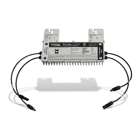
Installation Manual
Generac PV Link™ and SnapRS™
Loss of life. This product is not intended to
be used in a critical life support application.
Failure to adhere to this warning could result
in death or serious injury.
Register your Generac product at:
https://pwrfleet.generac.com
http://www.generac.com/service-support/product-support-lookup
006087
WARNING
1-888-GENERAC
(888-436-3722)
010023
(000209b)
Advertisement
Table of Contents

Subscribe to Our Youtube Channel
Related Manuals for Generac Power Systems PV Link


Summary of Contents for Generac Power Systems PV Link
- Page 1 Installation Manual Generac PV Link™ and SnapRS™ 010023 006087 WARNING Loss of life. This product is not intended to be used in a critical life support application. Failure to adhere to this warning could result in death or serious injury.
- Page 2 Individual operating habits and usage may contribute to the need for additional maintenance or service. Table 1 - PV Link and SnapRS Important Information PV Link Parallel Number of SnapRS Date of...
-
Page 3: Table Of Contents
Maintenance ........21 Electrical Hazards ......3 Service ...........21 Section 2 General Information ..5 Section 8 Troubleshooting ..23 PV Link Specifications ..... 5 SnapRS Specifications ....5 Unit Dimensions ......6 About PV Link ......... 7 About Generac SnapRS ....7 GFCI Information ...... -
Page 4: Section 1 Introduction And Safety
DANGER This manual provides instructions for installing Indicates a hazardous situation which, if not avoided, PV Link and SnapsRS devices. Consult the will result in death or serious injury. installation and operation manuals for other Generac PWRcell system components, as (000001) applicable. -
Page 5: General Hazards
WARNING over a dry wood platform. Work on this equipment only while standing on such Hot Surfaces. Locate and install the PV Link so as to avoid insulative mats. inadvertant contact. When operating in hot weather the optimizer will become hot and could result in personal •... -
Page 6: Electrical Hazards
(000666) WARNING Electrocution. Potentially lethal voltages are generated by this equipment. Render the equipment safe before attempting repairs or maintenance. Failure to do so could result in death or serious injury. (000187) Installation Manual for PV Link and SnapRS... - Page 7 This page is intentionally left blank Installation Manual for PV Link and SnapRS...
-
Page 8: Section 2 General Information
(g) 3.5 (100) * 1 SnapRS per PV module. ** Used with a 50 V PV Panel. Specifications are subject to change without notice. Refer to the product specification sheet for complete list. Installation Manual for PV Link and SnapRS... -
Page 9: Unit Dimensions
SnapRS Date of Manufacture Refer to to locate the unit date of Figure 2-2 manufacture. Record this information i Table 1: PV Link and SnapRS Important Infor- mation on the inside front cover of this man- ual. Figure 2-4. Unit Dimensions... -
Page 10: About Pv Link
(PLC) protocol for communicating with inverters and other devices on REbus. The PV Link is sealed in a type 3R enclosure at the factory and is designed for attachment to standard PV racking. Safety features include ground fault detection, arc fault detec- tion, and rapid shutdown capability. - Page 11 SnapRS Component Locations 010050 Figure 2-6. Component Locations Positive PV Connector Negative PV Connector Installation Manual for PV Link and SnapRS...
-
Page 12: Section 3 Installation Design
Section 3 Installation Design Installation Design Worksheet Use this worksheet to determine the maximum 3. Divide the PV Link VMP (Voltage at Maxi- mum Power) by the panel VMP and round number of PV modules of a given type that down to determine the number of panels can be connected to a PV Link. - Page 13 This page is intentionally left blank Installation Manual for PV Link and SnapRS...
-
Page 14: Section 4 Pvrss Compliance Guidelines
Generac PWRcell Inverter Installation tiation device. Manual. NOTE: Provide signage indicating the PVRSS 2. Install the PV Link as specified in this man- ual. initiation device is the REbus PV DC discon- nect located under the front cover of the 3. - Page 15 This page is intentionally left blank Installation Manual for PV Link and SnapRS...
-
Page 16: Section 5 Mounting And Connecting
Ungrounded Structures WARNING • Use two fasteners appropriate for the struc- ture. Hot Surfaces. Locate and install the PV Link so as to avoid inadvertant contact. When operating in hot weather the • See 5-1. Fasten to grounding termi- Figure... -
Page 17: Connecting To Inverter
PV Link output 1. Connect the negative lead of the first mod- before installing PV modules. ule in the string to the PV Link at the loca- tion marked PV Substring Input (-). See • Do not connect PV Link optimizers in... - Page 18 5-4. PV modules are installed in for combining PV modules together with series with SnapRS devices connected SnapRS.. inline between each module. 6. Make a string map using the PV Link peel- • See Figure 5-5. High-voltage modules can and-stick serial number stickers and be configured in parallel strings.
- Page 19 PV modules, and there must be one SnapRS device for each module in the array. Figure 5-5. Parallel-Input PV Array with SnapRS Devices PWRcell inverter PV module PV Link MC4 branch connector SnapRS device Installation Manual for PV Link and SnapRS...
-
Page 20: Section 6 Operating Instructions
Enable w/PVRSS to enter the Commissioning the Rebus Testing PVRSS state. System The PV Link ships from the factory in a dis- PV Link S2502 Menu abled state. Each unit must be enabled from the PWRcell inverter control panel. Once... - Page 21 6. See Figure 6-5. The LCD will display Test- 7. Complete steps 1-6 for each PV link in the ing PRVSS during the testing process. system. Upon completion, the LCD will read Low NOTE: To verify a PV Link is working properly, Sun or Making Power, depending upon navigate to the Mod.Settings page and con-...
-
Page 22: Disabling Pv Link
PV Link. minutes. Upon successful completion, the dis- 2. Press the center button to enter device play will read: Test Success. The PV Link (s) settings. will automatically re-enable. 3. Use the up and down arrows to highlight Disable and press the center button to select. - Page 23 This page is intentionally left blank Installation Manual for PV Link and SnapRS...
-
Page 24: Section 7 Maintenance
Section 7 Maintenance Service WARNING If the PV Link is not operating as expected, or if a PV Link error message appears on the Equipment damage. Never open the PV Link. The optimizer is factory-sealed and contains no field- Generac PWRcell Inverter control panel LCD serviceable parts. - Page 25 This page is intentionally left blank Installation Manual for PV Link and SnapRS...
-
Page 26: Section 8 Troubleshooting
Section 8 Troubleshooting CAUTION Equipment damage. Connect the PV Link output to a REbus- compatible device (± 190 VDC nominal regulated DC bus) only. Connecting to conventional PV inverters or any other device could cause equipment damage. (000659) There are no functional tests that can be per- formed on SnapRS devices in the field. - Page 27 This page is intentionally left blank Installation Manual for PV Link and SnapRS...
- Page 28 ©2020 Generac Power Systems, Inc. All rights reserved Specifications are subject to change without notice. Generac Power Systems, Inc. No reproduction allowed in any form without prior S45 W29290 Hwy. 59 written consent from Generac Power Systems, Inc. Waukesha, WI 53189 1-888-GENERAC (1-888-436-3722) www.generac.com...
Need help?
Do you have a question about the PV Link and is the answer not in the manual?
Questions and answers