
Related Manuals for Leica Geosystems TM6100A


Summary of Contents for Leica Geosystems TM6100A
- Page 1 Leica TM6100A User Manual ±¾ÎÄÓÉÌìÀÖ²â»æÍø£¨www.tleer.cn£©ÕûÀíÌṩ Version 1.0 English...
- Page 2 The type and the serial number of your product are indicated on the type plate. identification Enter the type and serial number in your manual and always refer to this information when you need to contact your agency or Leica Geosystems authorized service work- shop. Type: _______________ Serial No.:...
- Page 3 CompactFlash and CF are trademarks of SanDisk Corporation • Bluetooth is a registered trademark of Bluetooth SIG, Inc All other trademarks are the property of their respective owners. Validity of this Description manual General This manual applies to all TM6100A instruments. Introduction TM6100A...
- Page 4 Overall comprehensive guide to the product and Reference program functions. Included are detailed descriptions Manual of special software/hardware settings and soft- ware/hardware functions intended for technical specialists. Refer to the following resources for all TM6100A documentation and soft- ware • the TPS6000 Product CD • http://metrology.leica-geosystems.com/en/Downloads_6843.htm...
-
Page 5: Table Of Contents
System Concept 1.2.1 Software Concept 1.2.2 Data Storage and Data Conversion Concept 1.2.3 Power Concept Container Contents Instrument Components User Interface Keyboard Hot Key Assignments Screen Operating Principles Icons Operation Instrument Setup Battery 3.2.1 Operating Principles Table of Contents TM6100A... - Page 6 TM6100A Table of Contents 3.2.2 Instrument Battery Working with the CompactFlash Card Accessing Survey Application Program Built-in autocollimation device Connection to Application Computer Limitation of the horizontal and vertical movements Check & Adjust Overview Preparation Combined Adjustment (l, t, i and c)
- Page 7 Laser Plummet Electromagnetic Compatibility EMC FCC Statement, Applicable in U.S. Technical Data Angle Measurement Conformity to National Regulations 7.2.1 Communication side cover with Bluetooth General Technical Data of the Instrument International Limited Warranty, Software License Agreement Table of Contents TM6100A...
-
Page 8: Description Of The System
• connected with LGO Tools to view, exchange and manage data. Application Third party metrology software with an interface to the TM6100A Software for acquisition, analysis, management and reporting of data. LGO Tools An office software consisting of a suite of standard and extended... - Page 9 Description Total Station Positioning System LGO Tools LEICA Geo Office Tools Motorised TM6100A instruments are fitted with internal motors, enabling automatic horizontal and vertical turning are referred to as Motorised. Communication Communication side cover with integrated Bluetooth is a compo- side cover nent with external devices, i.e.
- Page 10 Description TM6100A Electronic theodolite, motorised, 0.5" accuracy. LEICA Geo Office • LGO Tools supports TM6100A instruments. It also supports all other Leica TPS Tools instruments. • LGO Tools is based on a graphical user interface with standard Windows® oper- ating procedures.
-
Page 11: System Concept
System Concept 1.2.1 Software Concept Description TM6100A instruments support the following types of software. Software type Software type Description System This software comprises the central functions of the instrument. software It is also referred to as firmware. The programs Survey and Setup are integrated into the firmware and cannot be deleted. - Page 12 Third party appli- There are various third party applications available for the cation programs TM6100A, onboard or computer based software. Please contact your Leica Geosystems representative for details. Customised Customised software specific to user requirements can be devel- application oped using the GeoC++ development kit.
-
Page 13: Data Storage And Data Conversion Concept
Available capacity: 256 MB. Unplugging connecting cables or removing the CompactFlash card during the meas- urement may cause loss of data. Always return to TM6100A Main Menu before removing the CompactFlash card and switch off the instrument before removing cables. - Page 14 TM6100A 1 - 14 Description of the System Data conversion Export Data can be exported from a job in a wide range of ASCII formats. A standard set of Export Formats is delivered with the system. Customized export format can defined in Format Manager which is a PC tool in LEICA Geo Office Tools.
-
Page 15: Power Concept
Power Concept General Use the Leica Geosystems batteries, chargers and accessories or accessories recom- mended by Leica Geosystems to ensure the correct functionality of the instrument. Power options Instrument Power for the instrument can be supplied either internally or externally. An external battery is connected to the instrument using a LEMO cable. -
Page 16: Container Contents
TM6100A 1 - 16 Description of the System Container Contents a) Protective cover for instrument and Container for sunshade for objective lens instrument and b) Container straps delivered c) Counterweight for diagonal eyepiece or accessories zenith eyepiece - optional d) Allen key... -
Page 17: Instrument Components
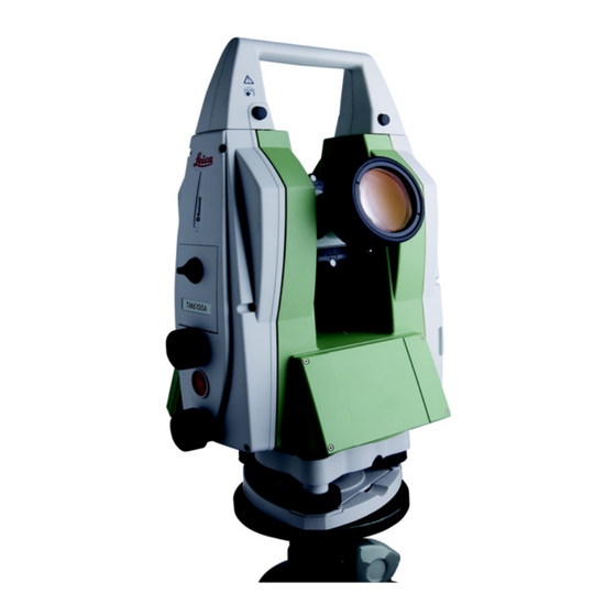
Instrument Components Instrument The instrument components of a TM6100A instrument are shown below. components part 1 of 2 a) Carry handle b) Optical sight c) Panfocal telescope d) CompactFlash card compartment e) Horizontal drive User defined SmartKey g) Vertical drive... - Page 18 TM6100A 1 - 18 Description of the System Instrument components part 2 of 2 Vertical drive k) Focusing ring Autocollimation device m) Interchangeable eyepiece n) Battery compartment o) Stylus for touch screen p) Screen q) Circular level Footscrew s) Keyboard...
- Page 19 Internal target An internal target GUS29 may be factory fitted to the telescope of the TM6100A to facilitate the mutual accurate collimation of two theodolites. Depending on the measurement task, the internal target can be rotated into or out of position.
-
Page 20: User Interface
TM6100A User Interface User Interface Keyboard Keyboard / $% _ @& * ? ! USER PROG PgUp SHIFT PgDn TM6100A_005... - Page 21 USER • Calls the user defined menu. PROG (ON) • If the instrument is off: to turn instrument on. • If the sensor is on: press at any time to select an applica- tion program. User Interface TM6100A...
- Page 22 TM6100A User Interface Description ENTER • Selects the highlighted line and leads to the next logical dialog/menu. • Starts the edit mode for edit fields. • Opens a list box. SHIFT • Changes between the first and the second level of func- tion keys.
- Page 23 PROG plus USER Turns instrument off. SHIFT F12 Calls STATUS Level & Laser Plummet. SHIFT F11 Calls CONFIGURE Lights, Display, Beeps, Text, Lights page. SHIFT USER Calls QUICK SET Change Settings to:. Pages up. SHIFT Pages down. SHIFT User Interface TM6100A...
-
Page 24: Hot Key Assignments
TM6100A User Interface Hot Key Assignments General TM6100A instruments contain two standard configurations at delivery. Two more configurations are available on the Factory CD. Configuration Set Description Angle Unit TM6100A BT Standard configuration set for Bluetooth Degree connection TM6100A Cable... - Page 25 Shift - F7 Compensator functions Shift - F8 Telescope accessories Shift - F9 Units & Formats Shift - F10 Battery & Memory Status Shift - F11 Lights & Display Settings Shift - F12 Electronic Level & Plummet User Interface TM6100A...
- Page 26 TM6100A User Interface Keyboard Overlay A self adhesive keyboard overlay is available for the default Hot Key assignments. The keyboard overlay can be affixed to the keyboard as shown below if required. USER USER PROG PROG PgUp PgUp SHIFT PgDn...
-
Page 27: Screen
Description screen Time The current local time is shown. Caption Shows location either in Main Menu, under PROG key or USER key. Title Name of the screen is shown. Screen area The working area of the screen. User Interface TM6100A... - Page 28 TM6100A User Interface Element Description Message line Messages are shown for 10 s. Icons Shows current status information of the instrument. Refer to "2.5 Icons". Can be used with touch screen. Can be used with touch screen. Same functionality as the fixed key ESC.
-
Page 29: Operating Principles
Step Description off step-by-step The instrument can only be turned off in TM6100A Main Menu. Press and hold both USER and PROG simultaneously. Press ESC for more then 2 s. Press YES (F6) to continue or NO (F4) to cancel. - Page 30 TM6100A User Interface Selecting Appearance Description from a menu To select an item from a menu, do one of the following: Move the focus to the item. ENTER or CONT (F1). Type the complete selection number in front of the item.
- Page 31 2. For the keyboard: ENTER. The edit mode is acti- vated where additional functions like insert and overwrite are available. 3. For the touch screen: Highlight the characters to be changed. 4. Type numeric and/or alphanumeric characters. 5. ENTER or tap outside of the field. User Interface TM6100A...
- Page 32 TM6100A User Interface Access special Step Description alphanumeric Highlight the input field. characters for input For the keyboard: ENTER. Toggle to the desired special character set by using the up/down arrow keys. Press the function key assigned to the required character group.
- Page 33 Choicelist shows items • Highlight the item and to select. ENTER. • A search field is shown • To exit without if necessary. changes ESC, tap outside the simple • A scroll bar is shown if listbox. necessary. User Interface TM6100A...
- Page 34 TM6100A User Interface Listbox dialog Appearance Description Selection • Choicelist fills the • Highlight the item and whole screen. CONT (F1). • A search field is • To exit without shown. changes press ESC or • A scroll bar is shown if necessary.
-
Page 35: Icons
Compensator/face I&II b) Bluetooth c) CompactFlash card/internal memory d) Battery e) SHIFT Quick coding Icons Icon Description Reflector The currently active reflector is displayed. Compensator/face I&II Compensator off, out of range or face I&II icon is displayed. User Interface TM6100A... - Page 36 TM6100A User Interface Icon Description Bluetooth The status of each Bluetooth port and any Bluetooth connection is displayed. CompactFlash The status of the CompactFlash card and internal card/internal memory memory are displayed. • For the CompactFlash card, the capacity of used space is shown in seven levels.
-
Page 37: Operation
• The laser plummet described in this topic is built into the vertical axis of the instrument. It projects a red spot onto the ground, making it appreciably easier to centre the instrument. • The laser plummet cannot be used in conjunction with a tribrach equipped with an optical plummet. Operation TM6100A... - Page 38 TM6100A Operation Setup step-by-step SHIFT TM6100A_007 Step Description Shield the instrument from direct sunlight and avoid uneven temperatures around the instrument. Extend the tripod legs to allow for a comfortable working posture. Position the tripod over the marked ground point, centring it as well as possible.
- Page 39 By using the electronic level turn the tribrach footscrews (6) to precisely level the instrument. Centre the instrument precisely over the ground point (4) by shifting the tribrach on the tripod plate (2). Repeat steps 6. and 7. until the required accuracy is achieved. Operation TM6100A...
-
Page 40: Battery
+10°C to +20°C/+50°F to +68°F if possible. • It is normal for the battery to become warm during charging. Using the chargers recommended by Leica Geosystems, it is not possible to charge the battery if the temperature is too high. Operation/Discharging •... -
Page 41: Instrument Battery
Face the instrument on the side with the single finedrive. The battery compartment is located just below. Turn the knob to the vertical position, opening the lid of the battery compartment. Pull out the battery housing. Pull the battery from the battery housing. Operation TM6100A... - Page 42 TM6100A Operation Step Description A pictogram of the battery is displayed inside the battery housing. This is a visual aid to assist in placing the battery correctly. Place the battery into the battery housing, ensuring that the contacts are facing outward. Click the battery into position.
-
Page 43: Working With The Compactflash Card
Use it only within the specified temperature range. • Do not bend the card. • Protect the card from direct impacts. Failure to follow these instructions could result in data loss and/or permanent damage to the card. Insert and remove a CompactFlash card step-by-step TM6100A_009 Operation TM6100A... - Page 44 TM6100A Operation Step Description Face the instrument so that the CompactFlash card compartment is on the right side of the instrument. Turn the knob to the vertical position, opening the lid of the CompactFlash card compartment. Open the lid of the CompactFlash card compartment.
- Page 45 YES (F4) to complete the formatting of the CompactFlash card. NO (F6) to abort the formatting of the CompactFlash card and return to TOOLS Format Memory Device. Once the formatting of the CompactFlash card is completed the system returns to TM6100A Main Menu. Operation TM6100A...
-
Page 46: Accessing Survey Application Program
TM6100A Operation Accessing Survey Application Program Access Select Main Menu: Survey. Press PROG. Highlight Survey. CONT (F1). SURVEY Survey Begin CONT (F1) To accept changes and access the subsequent screen. The chosen settings become active. CONF (F2) To access SURVEY Configuration. - Page 47 If codes have not been copied from a System RAM codelist but typed in manually, then the name of the active job is displayed. <Config Set:> Choicelist The active configuration set. All configuration sets from Main Menu: Manage...\Configura- tion Sets can be selected. Operation TM6100A...
- Page 48 TM6100A Operation Field Option Description The instrument has numerous user configuration parameters and functions. This allows a variety of preferences to be addressed. The configura- tion of the parameters and functions for an indi- vidual measuring technique are combined in a configuration set.
-
Page 49: Built-In Autocollimation Device
Built-in autocollimation device AL51 plug-in lamp The TM6100A is equipped with a built-in autocollimation device. To illuminate the autocollimation reticule and project it to an autocollimation mirror, plug the AL51 plug-in lamp into the socket on the telescope. Illumination To switch the illumination on or off select SHIFT (F11) to access CONFIGURE Lights Display, Beeps, Text. - Page 50 TM6100A Operation a) Intensity actuator TM6100A_041...
-
Page 51: Connection To Application Computer
Connection to Application Computer Connection types There are three basic connection types to connect a TM6100A to an application computer: • Cable connection via T-LINK • Cable connnection via USB Download Cable GEV218 or Y-Cable GEV220 • Wireless Bluetooth connection... - Page 52 TM6100A Operation T-LINK The connection via T-LINK connects up to 8 TM6100A to an application computer. The connection requires the following components: • T-LINK • Data Cable GEV86-I (20 m) • Data transfer cable to RS232 port of the application computer.
- Page 53 Direct cable The direct cable connection connects a single instrument to an application computer. connection The connection requires the following components: • USB Download Cable GEV218 or Y-Cable GEV220 TM6100A_011 Operation TM6100A...
- Page 54 TM6100A Operation Bluetooth connec- A Bluetooth connection to an application computer can be established through the tion internal bluetooth modul. The connection requires the following setup: • Paired bluetooth communication between TM6100A and application computer. TM6100A_012...
-
Page 55: Limitation Of The Horizontal And Vertical Movements
Limitation of the horizontal and vertical movements General Due to the size of the panfocal telescope of the TM6100A a face change can only be done through the lens side. This requires a turning restriction for the vertical move- ment of the telescope. - Page 56 TM6100A Operation Free turning range for eyepiece: Zenith Lens Lens Eyepiece Eyepiece 55 gon 344 gon TM6100A_042 Custom limitations In case of additional accessories used on the telescope, Individual limitations can be applied to the horizontal and vertical movements. Access...
- Page 57 CONFIGURE, Tele- scope Accessories, CONT (F1) Hz Limits To accept changes and return to the TM6100A Main Menu. NEW (F2) To define new horizontal limits for motorized rotation. SHOW (F5) To position the telescope to its rota- tion limits. PAGE (F6) To change to another page on this screen.
- Page 58 PAGE (F6) to change to the V Limit page. CONFIGURE, Tele- scope Accessories, CONT (F1) V Limits To accept changes and return to the TM6100A Main Menu. NEW (F2) To define new horizontal limits for motorized rotation. SHOW (F5) To position the telescope to its rota- tion limits.
- Page 59 <V End:> None Instruments turns without any limitation. <Use Limit:> Do not use with TM6100A. Eyepiece The movement of the telescope is limited by the stored Eyepiece Accessories limits. The movement of the telescope is limited by Lens the stored Lens Accessories limits.
-
Page 60: Check & Adjust
TM6100A Check & Adjust Check & Adjust Overview Description Leica instruments are manufactured, assembled and adjusted to the best possible quality. Quick temperature changes, shock or stress can cause deviations and decrease the instrument accuracy. It is therefore recommended to check and adjust the instrument from time to time. - Page 61 As mentioned above, these errors can change and it is highly recom- mended to redetermine them in the following situations: • Before the first use • Before every high precision survey • After rough or long transportations • After long working periods Check & Adjust TM6100A...
- Page 62 TM6100A Check & Adjust • After long storage periods • If the temperature difference between current environment and the temperature at the last calibration is more than 20°C Summary of errors Instrument error Effects Effects Elimination Automatically to be adjusted...
-
Page 63: Preparation
15 min should be taken into account. Take the carry handle off the TM6100A when calibrating and measuring as the tele- scope may not turn to the second face with the carry handle mounted. - Page 64 TM6100A Check & Adjust Next step IF the task is to THEN adjust a combination of Refer to "4.3 Combined Adjustment (l, t, i and c)" instrument errors adjust the tilting axis Refer to "4.4 Tilting Axis Adjustment (a)" adjust the circular level Refer to "4.5 Adjusting the Circular Level of the Instru-...
-
Page 65: Combined Adjustment (L, T, I And C)
Hz collimation error, also called line of sight error Combined The following table explains the most common settings. adjustment Step Description procedure step-by-step Main Menu: Tools...\Check & Adjust... TOOLS Check & Adjust Menu Select the option: Combined (l,t,i,c,ATR) TOOLS Combined I Check & Adjust TM6100A... - Page 66 TM6100A Check & Adjust Step Description Aim the telescope accurately at a target at about the usual working distance. The target must be positioned within ± 9°/± 10 gon of the horizontal plane. The procedure can be started in any telescope face.
- Page 67 Step Description MEAS (F1) to measure and to continue to the next screen. TM6100A are motorised instruments and change automatically to the other face. 180° The fine pointing has to be performed manually in both faces. 180° TM6100A_014 TOOLS Combined II MEAS (F1) to measure the same target in the other face and to calculate the instrument errors.
- Page 68 TM6100A Check & Adjust Step Description <No.of Meas:> Shows the number of runs executed. One run consists of a measurement in face I and face II. <σ l Comp:> and similar lines show the standard deviations of the deter- mined adjustment errors. The standard deviations can be calculated from the second run onwards.
-
Page 69: Tilting Axis Adjustment (A)
The following table explains the most common settings. tilting axis error Step Description step-by-step The Hz collimation error (c) has to be determined before starting this procedure. Main Menu: Tools...\Check & Adjust... TOOLS Check & Adjust Menu Select the option: Tilting Axis (a) Check & Adjust TM6100A... - Page 70 TM6100A Check & Adjust Step Description TOOLS Tilting-Axis Adjustment I Aim the telescope accurately at a target at about the usual working distance. The target must be positioned at least 27°/30 gon above or beneath the hori- zontal plane. The procedure can be started in any tele- + 27°...
- Page 71 Step Description MEAS (F1) to measure and to continue to the next screen. TM6100A are motorised instruments and change automatically to the other face. The fine pointing has to be performed manually in both faces. + 27° 180° - 27°...
- Page 72 TM6100A Check & Adjust Step Description If the error is bigger than the predefined limit, the procedure has to be repeated. The tilting axis measurements of the current run are then rejected and not averaged with the results from previous runs.
- Page 73 CONT (F1) overwrites the old tilting axis error with the new one. to be determined REDO (F2) rejects the new determined tilting axis error and again repeats the whole procedure. Refer to step 3. of paragraph "Determination of tilting axis error step-by-step". Check & Adjust TM6100A...
-
Page 74: Adjusting The Circular Level Of The Instrument And Tribrach
Adjusting the Circular Level of the Instrument and Tribrach Adjusting the circular level step-by-step SHIFT TM6100A 016 Step Description Place and secure the instrument into the tribrach and onto a tripod. Using the tribrach footscrews, level the instrument with the electronic level. - Page 75 Tribrach: If it extends beyond the circle, use the supplied allen key to centre it with the adjustment screws. After the adjustments, all adjusting screws should have the same tight- ening tension and no adjusting screw shall be loose. Check & Adjust TM6100A...
-
Page 76: Adjusting The Circular Level Of The Prism Pole
TM6100A Check & Adjust Adjusting the Circular Level of the Prism Pole Adjusting the Step Description circular level Suspend a plumb line. step-by-step Using a pole bipod, align the prism pole parallel to the plumb line. Check the position of the circular level on the prism pole. -
Page 77: Inspecting The Laser Plummet Of The Instrument
Leica Geosystems authorized service workshop. Inspecting the laser plummet step-by-step 360° SHIFT Ø 2.5 mm / 1.5 m ≤ 3 mm / 1.5 m TM6100A_018 The following table explains the most common settings. Check & Adjust TM6100A... - Page 78 If the centre of the laser dot describes a perceptible circular movement or moves more than 3 mm away from the point which was first marked, an adjustment may be required. Inform your nearest Leica Geosystems authorized service workshop. Depending on brightness and surface, the...
-
Page 79: Servicing The Tripod
Tighten the leg cap screws moderately, with the supplied allen key. Tighten the articulated joints on the tripod head just enough to keep the tripod legs open when lifting the tripod off the ground. Tighten the allen screws of the tripod legs. Check & Adjust TM6100A... -
Page 80: Adjustment Of The Autocollimation Reticule
TM6100A Check & Adjust Adjustment of the autocollimation reticule Description The built-in autocollimation device has an additional "negative" reticle, which is projected through the telescope and observed by the linear cross of the standard reticule. To achieve accurate results the negative reticule must coincide to the standard reti- cule. - Page 81 TM6100A_020 Check & Adjust TM6100A...
-
Page 82: Care And Transport
TM6100A Care and Transport Care and Transport Transport Telescope protec- To protect the telescope from damage, a protection cushion holds the telescope in tion cushion a particular position when the instrument is stored in the transport container. Posi- tion the telescope and attach the protection cushion according to the picture located... - Page 83 Always carry the product in its transport container and secure it. Shipping When transporting the product by rail, air or sea, always use the complete original Leica Geosystems packaging, transport container and cardboard box, or its equiva- lent, to protect against shock and vibration. Shipping, transport...
-
Page 84: Storage
TM6100A Care and Transport Storage Product Respect the temperature limits when storing the equipment, particularly in summer if the equipment is inside a vehicle. Refer to "7 Technical Data" for information about temperature limits. Field adjustment After long periods of storage inspect the field adjustment parameters given in this user manual before using the product. -
Page 85: Cleaning And Drying
Dry the product, the transport container, the foam inserts and the accessories at a temperature not greater than 40°C / 104°F and clean them. Do not repack until everything is completely dry. Always close the transport container when using in the field. Care and Transport TM6100A... - Page 86 TM6100A Care and Transport Cables and plugs Keep plugs clean and dry. Blow away any dirt lodged in the plugs of the connecting cables.
-
Page 87: Maintenance
Maintenance An inspection of the product must be done in a Leica Geosystems authorized service workshop. Leica Geosystems recommends an inspection of the product every 24 months. As TM6100A instruments are equipped with a self-surveillance system designed for maximum motor performance and long maintenance cycles Leica Geosystems recom- mends inspection of the product whenever indicated in the message line of the user interface. -
Page 88: Safety Directions
TM6100A Safety Directions Safety Directions General Introduction Description The following directions should enable the person responsible for the product, and the person who actually uses the equipment, to anticipate and avoid operational hazards. The person responsible for the product must ensure that all users understand these... -
Page 89: Intended Use
Opening the product using tools, for example screwdriver, unless this is specifi- cally permitted for certain functions. • Modification or conversion of the product. • Use after misappropriation. • Use of products with obviously recognizable damages or defects. Safety Directions TM6100A... - Page 90 TM6100A Safety Directions • Use with accessories from other manufacturers without the prior explicit approval of Leica Geosystems. • Aiming directly into the sun. • Inadequate safeguards at the working site, for example when measuring on roads. • Deliberate dazzling of third parties.
-
Page 91: Limits Of Use
Danger Local safety authorities and safety experts must be contacted before working in hazardous areas, or in close proximity to electrical installations or similar situations by the person in charge of the product. Safety Directions TM6100A... -
Page 92: Responsibilities
Manufacturers The manufacturers of non Leica Geosystems accessories for the product are respon- of non sible for developing, implementing and communicating safety concepts for their... -
Page 93: Hazards Of Use
Caution Reflectors can cause personal injury and/or mechanical damage, when dropped. Precautions: Secure the reflector with a lanyard when moving the reflector. Safety Directions TM6100A... - Page 94 TM6100A Safety Directions Warning Mounting the sensor on unstable or uneven ground may cause the sensor to tip over or cause unreliable measurement results. Precautions: Ensure the ground is stable and even. Do not place the sensor over cracks in the floor.
- Page 95 Inadequate securing of the measurement site can lead to dangerous situations, especially at industrial installations. Precautions: Always ensure that the measurement site is adequately secured. Adhere to the regu- lations governing safety and accident prevention and road traffic. Safety Directions TM6100A...
- Page 96 TM6100A Safety Directions Warning Only Leica Geosystems authorized service workshops are entitled to repair these products. Warning If computers intended for use indoors are used in the field there is a danger of elec- tric shock. Precautions: Adhere to the instructions given by the computer manufacturer with regard to field use in conjunction with Leica Geosystems products.
- Page 97 Before transportation or shipping contact your local passenger or freight transport company. Warning Using a battery charger not recommended by Leica Geosystems can destroy the batteries. This can cause fire or explosions. Precautions: Only use chargers recommended by Leica Geosystems to charge the batteries.
- Page 98 Always prevent access to the product by unauthorized personnel. Product specific treatment and waste management information can be downloaded from the Leica Geosystems home page at http://www.leica-geosystems.com/treat- ment or received from your Leica Geosystems dealer.
-
Page 99: Laser Classification
Products classified as laser class 2 or class 3R may cause dazzle, flash- blindness and afterimages, particularly under low ambient light conditions. Safety Directions TM6100A... - Page 100 TM6100A Safety Directions Labelling Art.No.: Type: TM6100A 576372 Equip.No.: ..S.No.: Power: 12V/14,8V ---, 2,5A max ..Leica Geosystems AG CH-9435 Heerbrugg Manufactured: ..Made in Switzerland Complies with FDA performance standards for laser products except for deviations pursant to Laser Notice No.50, dated June 24, 2007.
-
Page 101: Laser Plummet
These products are safe for momentary exposures but can be hazardous for delib- erate staring into the beam. Description Value Maximum average radiant power 1.00 mW Pulse duration c.w. Pulse repetition frequency c.w. Wavelength 620 nm - 690 nm Safety Directions TM6100A... - Page 102 From a safety perspective class 2 laser products are not inherently safe for the eyes. Precautions: Avoid staring into the beam or pointing the beam at other people. Labelling Art.No.: Type: TM6100A 576372 Equip.No.: ..S.No.: Power: 12V/14,8V ---, 2,5A max .
- Page 103 TM6100A_023 a) Laser beam b) Exit for laser beam Safety Directions TM6100A...
-
Page 104: Electromagnetic Compatibility Emc
Warning Electromagnetic radiation can cause disturbances in other equipment. Although the product meets the strict regulations and standards which are in force in this respect, Leica Geosystems cannot completely exclude the possibility that other equipment may be disturbed. Caution There is a risk that disturbances may be caused in other equipment if the product is... - Page 105 Although the product meets the strict regulations and standards which are in force in this respect, Leica Geosystems cannot completely exclude the possibility that the product may be disturbed by very intense electromagnetic radiation, for example, near radio transmitters, two-way radios or diesel generators.
- Page 106 Although the product meets in combination with radio or digital cellular phone devices recommended by Leica Geosystems the strict regulations and standards which are in force in this respect, Leica Geosystems cannot completely exclude the possibility that other equipment may be disturbed or that humans or animals may be affected.
-
Page 107: Fcc Statement, Applicable In U
FCC Statement, Applicable in U.S. Applicability The greyed paragraph below is only applicable for products of the TM6100A System without radio, digital cellular phone devices or Bluetooth. Warning This equipment has been tested and found to comply with the limits for a Class B digital device, pursuant to part 15 of the FCC rules. - Page 108 TM6100A Safety Directions Warning Changes or modifications not expressly approved by Leica Geosystems for compli- ance could void the user's authority to operate the equipment. Labelling Art.No.: Type: TM6100A TM6100A 576372 Equip.No.: ..S.No.: Power: 12V/14,8V ---, 2,5A max .
- Page 109 This device complies with part 15 of the FCC Rules. Operation is subject to the following two conditions: (1) This device may not cause harmful interference, and (2) this device must accept any interference received, including TM6100A_043 Safety Directions TM6100A...
-
Page 110: Technical Data
TM6100A Technical Data Technical Data Angle Measurement Accuracy Type Std. Dev. Hz, V, Display least count ISO 17123-3 ["] [mgon] ["] [mgon] TM6100A 0.15 0.01 0.01 Characteristics Absolute, continuous, quadruple... -
Page 111: Conformity To National Regulations
Conformity to • FCC Part 15 (applicable in US) • Hereby, Leica Geosystems AG, declares that the Communication side cover with national Bluetooth is in compliance with the essential requirements and other relevant regulations provisions of Directive 1999/5/EC. The declaration of conformity may be consulted at http://www.leica-geosystems.com/ce. -
Page 112: General Technical Data Of The Instrument
TM6100A Technical Data General Technical Data of the Instrument Type Panfocal alignment telescope Telescope Image Erect Objective aperture 52 mm Clear objective diameter: 40 mm Focusing: Coarse and fine Field of view and magnification Focussing Field of view Magnification distance... - Page 113 + 47° (+52 gon) Special features Feature Description Built-in autocollimation device Green negative crosshair Illumination AL51 plug-in lamp, keyboard switch Compensator Type Setting accuracy Setting range ["] [mgon] [’] [gon] TM6100A 0.15 0.07 Compensation: Centralized quadruple axis compensation Level Technical Data TM6100A...
- Page 114 TM6100A Technical Data Circular level sensitivity: 6’/2 mm Electronic level resolution: 2" Display: 1/4 VGA (320 x 240 pixels), color, graphics Control unit capable LCD, illumination, touch screen Keyboard: 34 keys including 12 function keys, 12 alphanumeric keys and a user defined SmartKey, illumination Angle Display: 360°’", 360°...
- Page 115 Instrument Dimensions 79 mm 114 mm 248 mm 228 mm TM6100A_025 Instrument: 7.25 kg Weight Tribrach: 0.8 kg Internal battery GEB241: 0.43 kg Technical Data TM6100A...
- Page 116 TM6100A Technical Data Recording Data can be recorded onto a CompactFlash card or into internal memory. Type Capacity [MB] Number of measurements per MB CompactFlash card • 256, 1024 1750 Internal memory • 1750 Type: Visible red laser class 2...
- Page 117 Typical operating time: 12 - 18 h Environmental Temperature specifications Type Operating temperature Storage temperature [°C] [°C] TM6100A -20 to +50 -40 to +70 Leica CompactFlash -40 to +80 -40 to +80 cards, all sizes Battery internal -20 to +50...
- Page 118 TM6100A Technical Data Protection against water, dust and Type Protection sand TM6100A IP54 (IEC 60529) Humidity Type Protection TM6100A Max 95 % non condensing The effects of condensation are to be effectively counter- acted by periodically drying out the instrument.
-
Page 119: International Limited Warranty, Software License Agreement
Leica Geosystems. Such software is protected by copy- right and other laws and its use is defined and regulated by the Leica Geosystems Software License Agreement, which covers aspects such as, but not limited to, Scope of the License, Warranty, Intellectual Property Rights, Limitation of Liability, Exclusion of other Assurances, Governing Law and Place of Jurisdiction. - Page 120 You must not install or use the software unless you have read and accepted the terms and conditions of the Leica Geosystems Software License Agreement. Installa- tion or use of the software or any part thereof, is deemed to be an acceptance of all the terms and conditions of such license agreement.
- Page 121 Format card ...........45 Adjustment Errors Icon ..............36 View current ..........61 Insert card ............43 Angle Measurement .......... 110 Remove card ..........43 Antenna Safety instructions .........43 Communication side cover ......111 Compensator ............113 Automatic Corrections ........118 Container Contents For instrument ..........16 TM6100A...
- Page 122 TM6100A Control unit ............114 Conversion, data conversion ....... 14 FCC Statement ..........107 Corrections Frequency Band Automatic ............ 118 Communication side cover ......111 Data Conversion ..........13 GeoC++ Software Development Kit ......12 Data Storage ............13 GUS29 ..............19 Dimensions Of instrument ..........115 Hazards of Use ............93...
- Page 123 Integrated Distancer, Invisible Laser ..... 100 Page, selecting from a .........30 Laser Plummet ..........101 Pages down ............23 PowerSearch PS ........... 101 Pages up .............23 Laser Plummet Ports ..............114 Adjustment ............ 77 Power Supply ............15 Technical data ..........116 TM6100A...
- Page 124 TM6100A PowerSearch PS ..........111 Language software .........11 Precise Measurements ........61 Software type ..........11 PROG ..............21 Software upload ..........12 System software ..........11 Software Concept ..........11 Quick coding, icon ..........36 Storage ...............84 Quick settings ............. 23 Survey Application ..........46 System Concept ..........11...
- Page 125 Tripod, service of ..........79 Unlock, keyboard ..........29 USB Download Cable ........... 53 USER ..............21 User Interface ............. 20 Value, edit in input field ........31 View Current Adjustment Errors ......61 Weight Of instrument ..........115 Y-Cable ............... 53 TM6100A...
- Page 126 International Standards of Quality Management and Quality Systems (ISO standard 9001) and Environmental Management Systems (ISO standard 14001). Ask your local Leica Geosystems dealer for more information about our TQM program. Leica Geosystems AG Heinrich-Wild-Strasse...
Need help?
Do you have a question about the TM6100A and is the answer not in the manual?
Questions and answers