Table of Contents
Advertisement
Advertisement
Chapters
Table of Contents

Related Manuals for Leica Geosystems SPRINTER 100


Summary of Contents for Leica Geosystems SPRINTER 100
- Page 1 LEICA SPRINTER User Manual Version 1.1 English...
- Page 2 SPRINTER 100/100M/200/200M is the new high quality electronic digital level produced by Leica Geosystems. It is designed to make levelling easier and quicker in any construc- tion site. It employs techniques that electronically read the special bar-coded staff and the gathered data is displayed on the screen almost instantly.
- Page 3 Important paragraphs which must be adhered to in practice as they enable the product to be used in a technically correct and efficient manner. Trademarks All trademarks are the property of their respective owners. SPRINTER 100/100M/200/200M...
-
Page 4: Table Of Contents
SPRINTER 100/100M/200/200M Table of Contents In this manual Chapter Page How to Use this Manual Description of the System Measurement Preparation User Interface Operation Data and Memory Management (only SPRINTER 100M/200M) Check & Adjust Messages Settings Care and Transport Safety Directions... -
Page 5: How To Use This Manual
Keys, fields and options on the screens which are considered as self-explanatory are not explained. Validity of this This manual is valid for both SPRINTER 100/200 and SPRINTER 100M/200M. Sections only valid for SPRINTER 100M/200M are marked accordingly. manual How to Use this Manual... - Page 6 How to Use this Manual SPRINTER 100/100M/200/200M Available Name of Description documentation documentation SPRINTER All instructions required in order to operate the instrument at its 100/100M/200/200M basic level are contained in this User Manual. Provides an over- User Manual view of the system together with technical data and safety directions.
-
Page 7: Description Of The System
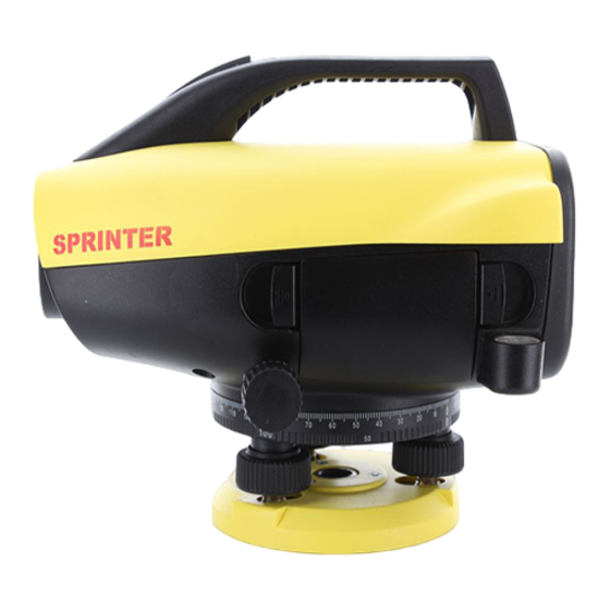
2 Description of the System Instrument components a) Horizontal fine motion screw b) Battery compartment Circular level d) Gunsight e) Focusing knob Handle g) Eyepiece h) LCD display Base plate Levelling footscrew Sprinter_01 Description of the System SPRINTER 100/100M/200/200M... - Page 8 Description of the System SPRINTER 100/100M/200/200M Container Contents a) SPRINTER b) Batteries (4x) Allen key d) Manual, CD-ROM e) Strap Sunshade (optional) g) Plumb adapter (optional) h) Plumb bob (optional)
- Page 9 Data Transfer / Recording to external device • Computer cable - serial interface (Optional) • Computer software • Leica Geo Office Tools for data downloading to PC • Documentation • User Manual • Quick-guide Description of the System SPRINTER 100/100M/200/200M...
-
Page 10: Measurement Preparation
Measurement Preparation SPRINTER 100/100M/200/200M 3 Measurement Preparation Topic Page In this chapter Battery Set-up instrument Battery Change battery step- by-step Sprinter_02 Sprinter_03... - Page 11 Set up the tripod. Extend the legs to a suitable length and ensure that the tripod head is approximately level. Tread the tripod shoes firmly into the ground to ensure stability. Mount the instrument on the tripod by screwing the tripod screw onto the base of the instrument. Measurement Preparation SPRINTER 100/100M/200/200M...
- Page 12 Measurement Preparation SPRINTER 100/100M/200/200M Step Description Use the three levelling foot screws to center the circular bubble in order to level the instrument. Turn the telescope of the instrument perpendicular to foot screws A and B. Turn foot screws A and B simultaneously in opposite direction until the bubble is in the center of the imaginary "T".
- Page 13 Otherwise, both steps 3 and 4 should be repeated. Use only SPRINTER staff produced by Leica Geosystems Power ON Sprinter_07 The instrument is ready to measure.
-
Page 14: User Interface
User Interface SPRINTER 100/100M/200/200M 4 User Interface Topic Page In this chapter Screen Display Operating Keys and Functions Modes Icons Menu Navigation Menu Setting Set of Characters 4.7.1 Entering Numeric Values 4.7.2 Entering Alphanumeric Values... -
Page 15: Screen Display
Screen Display MEAS a) Mode 1.235 b) Icons Measurement units 5.68 d) Distance symbol e) Height symbol Operating Keys and Functions Sprinter_08 Sprinter_09 User Interface SPRINTER 100/100M/200/200M... - Page 16 User Interface SPRINTER 100/100M/200/200M Pos. Key Symbol 1 level functions level functions On/Off Power On or Off switch NONE MEAS Measuring trigger key for 2nd function (Continuous measuring height and measurement) with distance prolonged key press of 2 seconds Height /...
-
Page 17: Modes
Modes Modes Symbol Mode Measurement Mode MEAS MENU selection Mode MENU Adjustment Mode Tracking Mode Icons Description Icons show the current status information of the instrument. Icon Description LCD backlight on Staff upright measuring mode User Interface SPRINTER 100/100M/200/200M... -
Page 18: Menu Navigation
User Interface SPRINTER 100/100M/200/200M Icon Description Inverted Staff measuring mode Different levels of LCD contrast display (10% change per step) Battery icon at various capacities (0%, 25%, 50%, 75%, 100%) External power utilized (applicable to SPRINTER 100M/200M) Data stored to internal memory (applicable to SPRINTER 100M/200M) -
Page 19: Menu Setting
2. Input RL 6. Inverse Staff 10. Rounding 3. Data Manager 7. Contrast 11. Beep 4. Recording 8. Units 12. Baudrate Menu Setting Sub Menus Selections Descriptions Input PtID To input user point ID (Applicable to SPRINTER 100M/200M) User Interface SPRINTER 100/100M/200/200M... - Page 20 User Interface SPRINTER 100/100M/200/200M Sub Menus Selections Descriptions Input Reduced Input for Benchmark value / Reference Level (RL) Reduced Level Data Manager View, Viewing of individual recorded data / Delete, deleting of specific measured target data Download Deleting of all measuring data...
- Page 21 Beep ON/OFF Acoustic signal trigger key ON or OFF RS232 (appli- Baudrate 1200, 2400, 4800, 9600, 19200, 38400 cable to SPRINTER Parity None, Odd, Even 100M/200M) Stop Bit 1, 2 Data Bit 7, 8 User Interface SPRINTER 100/100M/200/200M...
-
Page 22: Set Of Characters
User Interface SPRINTER 100/100M/200/200M Set of Characters Reduced level (RL) Reduced level (RL) numeric input consists of 0 ~ 9, space, decimal, Ft in 1/8 inch sepa- rator, the "+" and "-" signs. Point ID (PtID) Point ID (PtID) alphanumeric input consists of a ~ z, 0 ~ 9 and space. - Page 23 Use scrolling keys to highlight the desired character in the entry field. Acknowledge the character entry by pressing the ENTER key. The next entry field (to the right) is highlighted for further editing. Repeat step 2 and 3 until a complete value has been entered. User Interface SPRINTER 100/100M/200/200M...
- Page 24 User Interface SPRINTER 100/100M/200/200M Step Description To accept the new value, simply press the ENTER key with "space" character in the entry field at the end of the value string. A "Change RL. Are You Sure?" message is prompted, press ENTER key to confirm change.
- Page 25 E105 Invalid Entry ! Press key to continue. Accepting character If there is no change for any particular character in the existing entry field, press ENTER key to accept the old entry. in the existing value User Interface SPRINTER 100/100M/200/200M...
- Page 26 User Interface SPRINTER 100/100M/200/200M Clearing all the Highlighting the first entry field with "SPACE" and press ENTER key to clear the entire last reduced level input value. existing entry field Default Reference • If no Reference reduced level is input; the default value equals to zero, i.e. 0.000.
-
Page 27: Entering Alphanumeric Values
3. Data Manager 3. Data Manager Ext. 4. Recording 4. Recording MENU PtlD Enter Point No. 0.000 Meas. Reference PtlD : To change RL & ID goto menu Step Description Press Menu key to start menu for selection. User Interface SPRINTER 100/100M/200/200M... - Page 28 User Interface SPRINTER 100/100M/200/200M Step Description Use navigation keys to highlight the RECORDING, then press ENTER key. Use navigation keys to highlight the MEMORY (submenu of RECORDING), then press ENTER key. Use navigation keys to highlight the INPUT PtID, then press ENTER key.
- Page 29 If there is no change for any particular character in the existing entry field, press ENTER key to accept the old entry. Highlight the desired character to be change in entry field with the scrolling keys. User Interface SPRINTER 100/100M/200/200M...
- Page 30 User Interface SPRINTER 100/100M/200/200M Step Description Acknowledge the character entry by pressing the ENTER key. The next entry field (to the right) is highlighted for further editing. Repeat step 2 to 4 until a complete revised Point ID has been entered.
- Page 31 Clearing all the Highlighting the first entry field with "SPACE" and press ENTER key to clear the entire last Point ID input value. existing entry field User Interface SPRINTER 100/100M/200/200M...
-
Page 32: Operation
Operation SPRINTER 100/100M/200/200M 5 Operation Topic Page In this chapter Operating the Instrument Measuring in Progress 5.3.1 Height and Distance Measurement (internal Memory not active) 5.3.2 Height Difference, Reduced Level, Height and Distance Measurement (internal Memory not active) 5.3.3 Height and Distance Measurement with PtID (internal Memory active) 39 5.3.4... -
Page 33: Operating The Instrument
Operating the Instrument Switching ON/OFF a) ON/OFF switch b) Measure button Sprinter_24 • Switching ON: Press briefly. Version # : Serial # : SPRINTER 100M Logo displayed upon switching on Press any key to view and release version display Operation SPRINTER 100/100M/200/200M... -
Page 34: Measuring In Progress
Operation SPRINTER 100/100M/200/200M Measuring in Progress Height and distance measurement. Measurement MEAS : >>>> : >>>> Height and distance measurement with PtID. MEAS Memory should be ON to starts PtID display PtlD : >>>> >>>> Height, distance, reduced level and height difference measurement with PtID. -
Page 35: Height And Distance Measurement (Internal Memory Not Active)
1.235 : >>>> _ _ _ _ _ 5.68 1.235 5.68 : >>>> _ _ _ _ _ Measurement Measuring in Measurement Measurement Measurement Standby Mode progress with height and with with distance height only distance only Operation SPRINTER 100/100M/200/200M... - Page 36 Operation SPRINTER 100/100M/200/200M Step Description Press to switch on the instrument, Leica logo is displayed follow by the default measurement standby mode. Aim at staff and focus. Lightly trigger the measurement key to activate measurement. Height and distance measurement is displayed.
-
Page 37: Height Difference, Reduced Level, Height And Distance Measurement (Internal Memory Not Active)
MEAS 99.138 m - 0.900 m >>>> 2.135 m >>>> 31.11 m Measurement in Completion of meas- progress urement to target Step Key/Screen Description Press key to start height difference and reduced level function. Operation SPRINTER 100/100M/200/200M... - Page 38 Operation SPRINTER 100/100M/200/200M Step Key/Screen Description A message "Meas. Reference" with input reduced level is displayed. Press measuring key to initiate measurement with respect to the Reference staff / Benchmark. Reference height and distance measurement is displayed; follow by a message "Meas. Target!" prompted.
-
Page 39: Height And Distance Measurement With Ptid (Internal Memory Active)
With the internal memory set to active mode; the measuring procedures is the same as "5.3.2 Height Difference, Reduced Level, Height and Distance Measurement (internal Memory not active)". The measurement results displayed together with point ID. PtlD 99.138 m - 0.900 m 2.135 m 31.11 m Operation SPRINTER 100/100M/200/200M... -
Page 40: Measuring Modes
Operation SPRINTER 100/100M/200/200M With the Recording Ext set to active mode; the measuring procedure is the same as 5.3.3 and 5.3.4 without displaying the diskette icon. 5.3.5 Measuring Modes Description There are 2 different measuring modes to select: Single measurement and Tracking measurement.To Abort the measurement during single measuring mode by triggering the... -
Page 41: Special Measuring Situations
Results of last measurement will be displayed. Technical Hints for Measurements 5.4.1 Special Measuring Situations Vibrations Vibrations at the instrument, e.g. due to wind can be damped by touching the upper third of the tripod steadying the tripod. Operation SPRINTER 100/100M/200/200M... - Page 42 Operation SPRINTER 100/100M/200/200M Backlight Use the lens hood (optional accessory) to cover the objective when back light disturbs your work. As a last resort, use your hands to shield the objective from disturbing back- light. Darkness Evenly illuminate the measuring area of the staff with a flashlight or spotlight in darkness.
-
Page 43: Important Instrument Settings
(Sprinter only). See 2-peg level test (respective with collimator test). 2. Determine the values through your own measurements with procedures recom- mended in this booklet and enter them into the system ([MENU]/ Adjust / System by pressing the ENTER key). Operation SPRINTER 100/100M/200/200M... -
Page 44: Data And Memory Management (Only Sprinter 100M/200M)
Data and Memory Management (only SPRINTER 100M/200M) SPRINTER 100/100M/200/200M 6 Data and Memory Management (only SPRINTER 100M/200M) Topic Page In this chapter Viewing Data Downloading Data Deleting Data Description • The data is stored in internal memory or to an external device such as PDA, Data Collector or PC through the RS232 interface. - Page 45 A Data Point Counter (fraction number) located at first row of stored measure- ment data to indicate the current data sequence (numerator) and the total number (denominator) of data stored. Press key to exit from menu after viewing of data. Data and Memory Management SPRINTER 100/100M/200/200M (only SPRINTER 100M/200M)
- Page 46 Data and Memory Management (only SPRINTER 100M/200M) SPRINTER 100/100M/200/200M Downloading Data Access Downloading data is access via the Data Manager submenu - Download Data. Downloading data To download data, highlight Download Data and press ENTER key; "Down- loading Data!" and "Download Completed!" messages are displayed consecu- tively.
-
Page 47: Check & Adjust
(A and B are the staffs positions and x is the instrument position). Procedures Set up the SPRINTER 100/100M/200/200M in the center of the two staffs A and B. The distance between the two staffs is approximately 30m. Check & Adjust... - Page 48 Check & Adjust SPRINTER 100/100M/200/200M Staff A ~15m ~15m Staff B To activate the "Check and Adjust" program, press MENU-ADJUSTMENT and the first screen of the application appears as indicated below: Step 1 Aim at Staff A and press MEAS key. Measurement display, press ENTER key to accept/confirm.
- Page 49 Now shift the SPRINTER towards staff A and set it up at about 3 m to staff A. ~27m Step 3 Aim at Staff B and press MEAS key. Measurement display, press ENTER key to accept/confirm. MENU ADJ ADJUST (3/4) MEAS Check & Adjust SPRINTER 100/100M/200/200M...
- Page 50 Check & Adjust SPRINTER 100/100M/200/200M Step 4 Aim at Staff A and press MEAS key. Measurement display, press ENTER key to accept/confirm. MENU ADJ ADJUST (4/4) MEAS The new collimation error is displayed. MENU ADJ Error = 5.0” dH: = Accept To accept the correction, press ENTER key.
- Page 51 Firmly tighten Allen screw (b) (if one is used). Tighten the joint on the tripod head (a) just enough so that with the legs extended, the tripod can be lifted off the ground and the legs remain in the same position. Check & Adjust SPRINTER 100/100M/200/200M...
- Page 52 Check & Adjust SPRINTER 100/100M/200/200M Circular Level Sprinter_18 Sprinter_19 Step Description Level instrument. Turn instrument by 180°. Center bubble if it extends beyond the centering circle. Correct half of the error with the Allen key. Repeat steps 1 to 4 until the circular level bubble is centered at any random...
- Page 53 Reticle Sprinter_20 If the collimation error exceeds 3 mm over 60 m distance, the collimation needs to be adjusted. Step Description Turn Allen key until design value is reached. Check collimation. Check & Adjust SPRINTER 100/100M/200/200M...
-
Page 54: Messages
Messages SPRINTER 100/100M/200/200M 8 Messages Topic Page In this chapter List of the "Error" Messages List of the "Operation" Messages List of the "Error" Messages Error message Counter measure / causes System Error, Contact Hardware faults or file errors or adjustment... - Page 55 Target Too far ! Move staff or instrument closer together. E112 Too Cold ! Stop working, external temperature is outside the instrument operating temperature. E113 Too Hot ! Stop working, external temperature is outside the instrument operating temperature. Messages SPRINTER 100/100M/200/200M...
- Page 56 Messages SPRINTER 100/100M/200/200M Error message Counter measure / causes E114 Invalid Measurement ! Make another measurement. If further meas- urement proved to be futile, check staff position and Inverse Staff setting, check the lighting condition at the staff and stray light, check focusing and targeting, check if sufficient length of barcode in the field of view.
- Page 57 (in View Data mode) or all the data (in Delete Data mode) in the internal memory. Data Deleted ! System confirmation that a data or all the data in the internal memory is deleted. Messages SPRINTER 100/100M/200/200M...
- Page 58 Messages SPRINTER 100/100M/200/200M Message Counter measure / remark Can't Delete ! Reference reduced level measurement is not allowed to be deleted by single data deletion method. No Reference Point ! Aim, focus and measure to a Reference point. In Height Difference and Reduced Level meas- urement, a Reference point measurement is required.
-
Page 59: Settings
PtID is not updated manually. Collimation error Displays the new collimation error immediately after the field adjustment. Upon accepting this new collimation error, the system will correct the electronic height measurement with this collimation error magnitude. Settings SPRINTER 100/100M/200/200M... - Page 60 Settings SPRINTER 100/100M/200/200M Data Output Important settings for measuring and display. GSI-format Data via interface and data export in GSI-format. • GSI-8 8-data characters output format (83..00+12345678). These data words can hold alpha as well as numeric data. • GSI-16 16-data characters output format (83..00+1234567890123456 ).
-
Page 61: Care And Transport
Always carry the product in its transport container and secure it. vehicle Shipping When transporting the product by rail, air or sea, always use the complete original Leica Geosystems packaging, transport container and cardboard box, or its equivalent, to protect against shock and vibration. Care and Transport SPRINTER 100/100M/200/200M... - Page 62 Care and Transport SPRINTER 100/100M/200/200M Shipping, transport When transporting or shipping batteries, the person in charge of the product must ensure that the applicable national and international rules and regulations are observed. Before of batteries transportation or shipping, contact your local passenger or freight transport company.
-
Page 63: Safety Directions
The following directions should enable the person responsible for the product, and the person who actually uses the equipment, to anticipate and avoid operational hazards. The person responsible for the product must ensure that all users understand these direc- tions and adhere to them. Safety Directions SPRINTER 100/100M/200/200M... -
Page 64: Intended Use
Safety Directions SPRINTER 100/100M/200/200M 11.2 Intended Use Permitted use • Electronic and optical height and distance measurements to a staff. • Recording of measurement data. Adverse use • Use of the product without instruction. • Aiming directly to the sun. -
Page 65: Limits Of Use
Manufacturers of The manufacturers of non Leica Geosystems accessories for the product are responsible for developing, implementing and communicating safety concepts for their products, and non Leica Geosys- are also responsible for the effectiveness of those safety concepts in combination with the tems accessories Leica Geosystems product. -
Page 66: International Warranty, Software Licence Agreement
Leica Geosystems. Such software is protected by copyright and other laws and its use is defined and regulated by the Leica Geosystems Software Licence Agreement, which covers aspects such as, but not limited to, Scope of the Licence, Warranty, Intellectual Property Rights, Limitation of Liability, Exclusion of other Assur- ances, Governing Law and Place of Jurisdiction. -
Page 67: Hazards Of Use
You must not install or use the software unless you have read and accepted the terms and conditions of the Leica Geosystems Software Licence Agreement. Installation or use of the software or any part thereof, is deemed to be an acceptance of all the terms and condi- tions of such licence agreement. - Page 68 Safety Directions SPRINTER 100/100M/200/200M Danger Because of the risk of electrocution, it is very dangerous to use poles and extensions in the vicinity of electrical installations such as power cables or electrical railways. Precautions: Keep at a safe distance from electrical installations. If it is essential to work in this environ- ment, first contact the safety authorities responsible for the electrical installations and follow their instructions.
- Page 69 Precautions: Adhere to the instructions given by the computer manufacturer with regard to field use in conjunction with Leica Geosystems products. Caution If the accessories used with the product are not properly secured and the product is subjected to mechanical shock, for example blows or falling, the product may be damaged or people may sustain injury.
- Page 70 Safety Directions SPRINTER 100/100M/200/200M Danger Using rechargeable batteries with an unsuitable charger may cause fire and explosions. Precautions: Only use rechargeable batteries and its appropriate charger recommended by Leica Geosystems. Warning Short circuited battery terminals can overheat and cause injury or fire, for example by storing or transporting in pockets if battery terminals come in contact with jewellery, keys, metallized paper of other materials.
- Page 71 Precautions: Dispose of the product appropriately in accordance with the regulations in force in your country. Always prevent access to the product by unauthorized personnel. Safety Directions SPRINTER 100/100M/200/200M...
-
Page 72: Electromagnetic Compatibility Emc
Caution Disturbances caused by electromagnetic radiation can result in erroneous measurements. Although the product meets the strict regulations and standards which are in force in this respect, Leica Geosystems cannot completely exclude the possibility that the product may... -
Page 73: Fcc Statement, Applicable In U.s
This equipment generates, uses and can radiate frequency energy and, if not installed and used in accordance with the instructions, may cause harmful interference to radio commu- nications. However, there is no guarantee that interference will not occur in a particular installation. Safety Directions SPRINTER 100/100M/200/200M... - Page 74 Connect the equipment into an outlet on a circuit different from that to which the receiver is connected. • Consult the dealer or an experienced radio/TV technician for help. Warning Changes or modifications not expressly approved by Leica Geosystems for compliance could void the user's authority to operate the equipment. Labelling SPRINTER ......
-
Page 75: Technical Data
Standard deviation per km double run (ISO 17123-2): ments Electronic measurement with SPRINTER aluminum barcode staff: 1.5mm (SPRINTER 200/200M), 2.0mm (SPRINTER 100/100M) Optical measurment with standard aluminum E-scale/Numeral staff: 2.5mm Standard Deviation for single staff reading: 0.6 mm (electronic) and 1.2 mm (optical) at 30 m... - Page 76 Technical Data SPRINTER 100/100M/200/200M Distance Accuracy 10 mm for D<= 10 m Distance in m x 0.001 for D>10 m (Standard Deviation) 12.2 Measuring Range Distance measuring range for electronic measurements Standard aluminum barcode staff: 2 m to 80 m...
- Page 77 500 points Internal Memory Storage Program (SPRINTER 100M/200M to PC): LGO Tools Data Transfer SPRINTER 100/200: internal battery Power Supply SPRINTER 100M/200M: internal battery and external via RS232 port Battery internal AA dry cells 4 x 1.5 V...
- Page 78 Technical Data SPRINTER 100/100M/200/200M Type: Monochrome display with backlight capability Dimensions: 128 x 104 pixels Magnification (Optical): 24 x Telescope Free objective diameter: 36 mm Clear Objective Aperture: 2 ° Multiplication constant: Addition constant: Circle Engraving: Plastic horizontal circle of 360° (400 gon). Graduation Hz Circle and numerals scale resolution at 1°(upper scale) and...
- Page 79 Width (from the external face of focusing drive to the 196 mm external side of circular bubble holder) Height (incl. hand grip, base fully extended) 178 mm Container Length 400 mm Width 220 mm Height 325 mm 2.55 kg (including 4 AA batteries) Weight Technical Data SPRINTER 100/100M/200/200M...
-
Page 80: Index
Index SPRINTER 100/100M/200/200M Index Objectives ............62 Collimation error ..........59 Accessories ............9 Communications parameters ......60 Accuracy .............. 75 Compensator ............76 Adjustment ............20 Contrast .............. 20 Alphanumeric Values .......... 27 AutoOFF .............. 21 Darkness ............. 42 Data Manager ............. - Page 81 Input PtID ............19 Modes ..............17 Input Reduced Level ........... 20 Instrument components ......... 7 Interface Numeric Values ........... 22 User ..............14 Internal Memory Storage ........77 Inverse Staff ............20 Operation Messages ........... 57 Index SPRINTER 100/100M/200/200M...
- Page 82 Index SPRINTER 100/100M/200/200M Side Drive ............78 Single measurement mode ......... 40 Page ..............5 Specifications, environmental ......75 Path ............... 5 Storage Point ID ............22, 27 Field adjustment ..........62 Power ON ............13 Product ............62 Power Supply ............77 Switching ON/OFF ..........
- Page 83 Tripod ..............51 Unit ..............20 User interface ............14 Vibrations ............41 Viewing data ............45 Weight ..............79 Index SPRINTER 100/100M/200/200M...
- Page 84 Environmental Manage- ment Systems (ISO standard 14001). Leica Geosystems AG 739380-1.1.0en CH-9435 Heerbrugg (Switzerland) Printed in Switzerland - Copyright Leica Geosystems AG, Heerbrugg, Phone +41 71 727 31 31 Switzerland 2004 Fax +41 71 727 46 73 Original text www.leica-geosystems.com...
Need help?
Do you have a question about the SPRINTER 100 and is the answer not in the manual?
Questions and answers