Table of Contents
Advertisement
Quick Links
Advertisement
Chapters
Table of Contents

Related Manuals for Furuno FA-40


Summary of Contents for Furuno FA-40
- Page 1 OPERATOR'S MANUAL 取扱説明書 AIS RECEIVER AIS受信機 FA-40 Model www.furuno.com...
- Page 2 (Elemental Chlorine Free) The paper used in this manual is elemental chlorine free. ・ 機器の修理・使用方法等に関するお問い合わせは、お買い上げの販売店・代理店、最寄りの 当社支店・営業所あてへお願いします。 ・ FURUNO Authorized Distributor/Dealer お問い合わせは 本書の無断複写複製(コピー)は特定の : FEB. 2020 場合を除き、当社権利侵害になります。 : APR. 2020 Printed in Japan Pub. No. OMC-45130-A1 ( YOTA) FA-40 00019740410...
- Page 3 How to discard a used battery Some FURUNO products have a battery(ies). To see if your product has a battery, see the chapter on Maintenance. If a battery is used, tape the + and - terminals of the battery before disposal to pre- vent fire, heat generation caused by short circuit.
- Page 4 SAFETY INSTRUCTIONS The operator and installer must read the applicable safety instructions before attempting to install or operate the equipment. Indicates a potentially hazardous situation which, if not WARNING avoided, could result in death or serious injury. Indicates a potentially hazardous situation which, if not CAUTION avoided, could result in minor or moderate injury.
- Page 5 0.3 m 0.3 m GPA-C01 Do not install the equipment where it may get wet from rain 0.3 m 0.3 m FA-40 Receiver or water splash. Power PR-240 0.9 m 0.6 m Water in the equipment can result...
-
Page 6: Table Of Contents
1.1 Equipment List ......................1-1 1.2 Included Items and Local Supplies ................1-3 1.3 Required Tools and Materials ..................1-4 1.4 AIS Receiver FA-40 ....................1-4 1.5 GPS Antenna (option) ....................1-5 1.6 VHF Antenna (option) ....................1-6 1.7 AC-DC Power Supply (option) ................... 1-7 1.8 Wiring ......................... -
Page 7: Foreword
FOREWORD A Word to the Owner of the FA-40 FURUNO Electric Company thanks you for purchasing the FURUNO FA-40 AIS Receiver. We are confident you will discover why the FURUNO name has become synonymous with quality and re- liability. Since 1948, FURUNO Electric Company has enjoyed an enviable reputation for quality and reli- ability throughout the world. -
Page 8: System Configuration
SYSTEM CONFIGURATION Antenna Unit GPA-017S, VHF Antenna GPA-017, CX4-3/FEC or GPA-C01 AIS Receiver FA-40 POWER ERROR NMEA2000 Sensor NAV Equipment or External Display or Sensor Ship’s Mains 12-24 VDC NAV Equipment or Sensor : Standard supply : Optional or local supply... -
Page 9: Installation
Installer.msi – setup.exe Install file of AIS setting tool USBDriver – cdc.cat Install file of USB driver ForWindows7 (required to connect the FA-40 FURUNO_AIS.inf with USB CDC) PC requirements ® ® Microsoft Windows 7 (32 bit / 64 bit), ®... - Page 10 1. INSTALLATION Optional supply Name Type Code No. Remarks Antenna Unit GPA-017 GPS antenna GPA-017S GPA-C01 AC/DC Power Supply PR-240 Unit Cable Assembly TNC-PS/PS-3D- 001-173-110-10 For GPA-017S, TNC- L15M-R TNC (15 m) FRU-NMEA- 001-533-060 Max. 6 m PMMFF-010 FRU-NMEA- 001-533-070 PMMFF-020 FRU-NMEA- 001-533-080...
-
Page 11: Included Items And Local Supplies
1. INSTALLATION Name Type Code No. Remarks Termination Resistor FRU- 001-507-070 (Micro) MM1000000001 FRU- 001-507-060 MF000000001 In-Line Terminator FRU-0505-FF-IS 001-077-830-10 Included Items and Local Supplies AIS Receiver • Tapping screws (4 pcs) • AIS Receiver (1 pcs) • AIS Setting Tool (1 pcs) •... -
Page 12: Required Tools And Materials
• Keep the unit away from electromagnetic field-generating equipment such as mo- tors and generators. • A magnetic compass will be affected if the FA-40 is placed too close to it. Observe the compass safe distances noted in the safety instructions to prevent disturbance to the magnetic compass. -
Page 13: Gps Antenna (Option)
1. INSTALLATION GPS Antenna (option) CAUTION Do not connect the GPS antenna connector to ground. Short circuit can result. Install the GPS antenna unit referring to the outline drawing at the back of this manual. When selecting a mounting location for the antenna, keep the following in mind: •... -
Page 14: Vhf Antenna (Option)
1. INSTALLATION VHF Antenna (option) Location The location of the VHF antenna should be carefully considered. It may be necessary to relocate the VHF radiotelephone antenna to minimize interference effects. To min- imize interference effects, the following guidelines apply: • Select a location out of the radar and inmarsat beams. Those beams will obstruct or prevent reception of the AIS signal. -
Page 15: Ac-Dc Power Supply (Option)
1. INSTALLATION How to attach the plug M-P-5 Lay the coaxial cable and attach an M-type plug to the cable as follows. Plug assembly Contact sleeve 30 mm Sheath 5 mm 2 mm Conductor Cut conductor Solder both Insulator Braided shield here. -
Page 16: Wiring
: Optional or local supply and the other supports version 2, connect one of the monitors to the NMEA0183 port. Note: The FA-40 does not have a power switch. Install an external device (power switchboard, etc.) from which to control its power. - Page 17 How to waterproof the connector for VHF antenna Wrap the connector for VHF antenna with vulcanizing tape. Connection with the PC and NavNet TZtouch2/3 The FA-40 may be connected to a PC or TZTL12F/TZTL15F/TZT12F/TZT16F/ TZT19F. See the figure below for connection examples. CAUTION PC connected by USB is only powered by a battery.
- Page 18 1. INSTALLATION This page is intentionally left blank. 1-10...
-
Page 19: Ship Information Input
SHIP INFORMATION INPUT The FA-40 is set up from the PC or external display (TZTL12F*/15F* or TZT12F/16F/ 19F). When setting from the PC, install the USB driver and PC software (see sections 2.1 and 2.2). When setting from the external display, open the home screen, and then select [Settings] - [Initial Setup] - [NETWORK SENSOR SETUP] - [FA-40] in order to display the menus. -
Page 20: How To Install The Ais Setting Tool
2. SHIP INFORMATION INPUT How to Install the AIS Setting Tool Note: Install the AIS setting tool with administration rights. 1. Set the supplied CD-ROM in the CD drive. 2. Click [AIS_Setting_Tool]. 3. Click [setup.exe]. 4. Click [Next]. 5. Click [Next]. To change the installation folder, click [Browse] and select the folder before clicking [Next]. -
Page 21: How To Start And Quit The Ais Setting Tool
2. SHIP INFORMATION INPUT 6. Click [Next] to start the installation. When the installation is completed, the dialog box shown below appears. 7. Click [Close] to finish. The shortcut icon for [AIS_Setting_Tool.exe] is created on your desktop. 8. Remove the CD-ROM from the CD drive. How to Start and Quit the AIS Setting Tool 1. -
Page 22: Overview Of The Ais Setting Tool
• [Connect]: Connects to the FA-40. • [Disconnect]: Disconnects from the FA-40. [Refresh All] Obtains the latest data from the FA-40, and then updates all settings of all menu tabs. [Apply All] Saves all settings in all tab pages, and then transmits the data to the FA-40. -
Page 23: Initial Setup
2. SHIP INFORMATION INPUT Initial Setup You can use the FA-40 without changing the settings for [Initial Setup]. If changing the settings, refer to the followings: [Status] ([AIS Status] on the external display), [MMSI], and [Serial Number]: Display only. [Initial Setup] menu for PC Most of the menu items are the same between the PC and external display. - Page 24 2. SHIP INFORMATION INPUT This page is intentionally left blank.
-
Page 25: Settings And Status
SETTINGS AND STATUS IO setup (input/output port) You can change the input/output settings from the [IO Setup] menu. [CAN Unique Number], [CAN Address]: Display only. [IO Setup] menu for PC Menu item Description [Common] [Port Priority (Heading)] Set the input port priority for heading data. [1st], [2nd], [3rd] [NMEA2000] [CAN Unique Number]... -
Page 26: Own Vessel Data Screen
3. SETTINGS AND STATUS Menu item Description [NMEA1 Output GNSS], When selecting [GNSS] or [AIS + GNSS] in the [NMEA1/NMEA2 Output [NMEA2 Output GNSS] Mode] menu, select the output GNSS sentence for NMEA1/NMEA2 among [OFF], [GGA + VTG (Sentences)], [GLL + VTG (Sentences)] or [RMC (Sentence)]. -
Page 27: Alert Status
[Screenshot] (for the PC) Click to take a screenshot. [Sensor Status] Shows the information about the sensors connected to the FA-40. • Internal/External DGNSS in Use: DGNSS currently in use. • Internal/External GNSS in Use: GNSS currently in use. • Internal/External SOG/COG in Use: SOG/COG currently in use. -
Page 28: Io Monitor
3. SETTINGS AND STATUS *: For the external display, select the alert ID to display the alert message on the bot- tom of the screen. For the PC, click [Open] of [Alert Log] to show the alerts that occurred in the past (max. 20 alerts). -
Page 29: Maintenance
If the unit cannot be powered, that is, the POWER LED does not light, the fuse may have blown. If this happens, turn off the power to the FA-40, and check the fuse. If the fuse has blown, find out the reason before replacing it. If it blows again after re- placement, contact your dealer for advice. -
Page 30: Troubleshooting
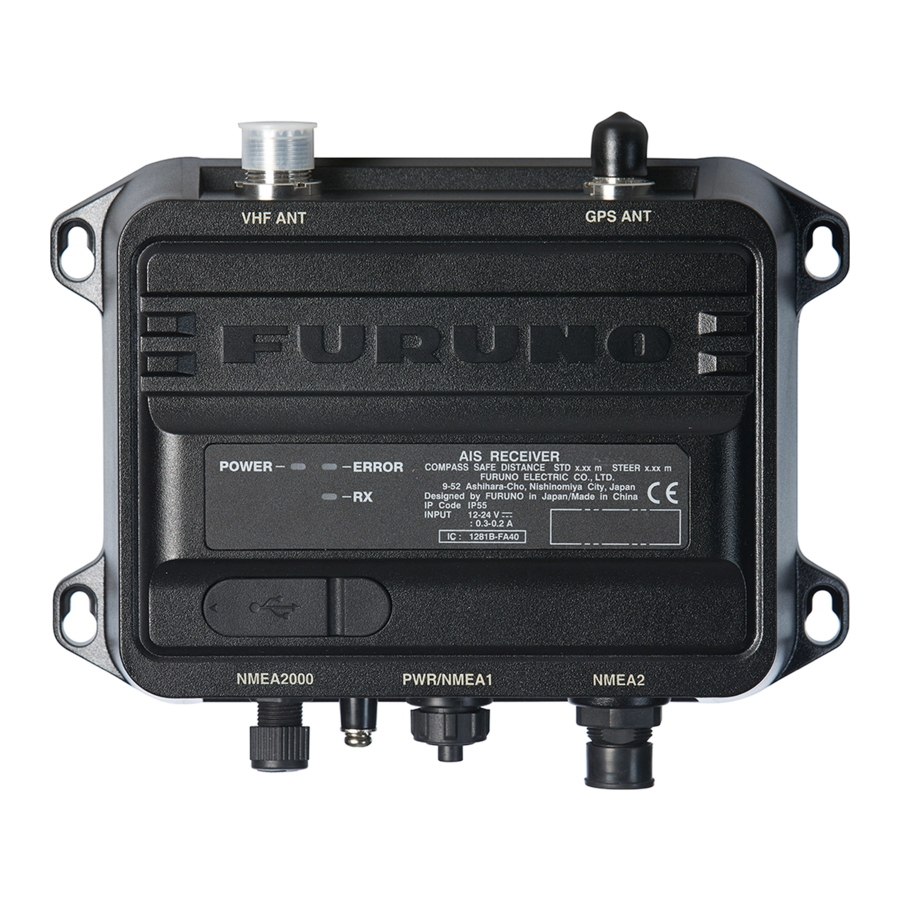
AIS Receiver FA-40 The FA-40 has no power switch. Power is fed from the ship's switchboard, and a pow- er switch on the switchboard turns the FA-40 on or off. The table below shows the function for each LED. -
Page 31: Diagnostics
4. MAINTENANCE Diagnostics The FA-40 provides diagnostic tests to check the receiver unit for proper operation. [Tests] screen for PC Menu item Description [Test Start] (for the PC) Click to start the test. [Transponder Test] The program version number appears on the first line. The RAM, ROM, and two RX channels (A and B) are checked for proper opera- tion, and the results are displayed as "OK"... - Page 32 4. MAINTENANCE This page is intentionally left blank.
-
Page 33: Appendix 1 Menu Tree
Alert Log (Shows the alerts occurred in the past.) Tests Test Start (Starts the test.) Transponder Test (Shows the self test result for the FA-40.) GNSS Test (Shows the self test result for the internal GNSS core.) Clear GNSS (Clears the GNSS test result.) - Page 34 APPENDIX 1 MENU TREE TZTL12F/15F, TZT12F/16F/19F On the home screen, select [Settings] - [Initial Setup] - [NETWORK SENSOR SETUP] - [FA-40] in order to display the menus. Menu Bold italic: Default AIS Status (Shows the status of AIS.) Initial Setup Ship Static MMSI (Shows the MMSI number.)
-
Page 35: Appendix 2 Alert Lists
APPENDIX 2 ALERT LISTS The table below shows the alert ID, text, meaning and remedy for each alert. Text Meaning Remedy 003 RX Channel 1 Malfunction RX1 hardware trouble. Re- Circuit board may be dam- ception stopped on corre- aged. Contact your dealer. sponding RX channel. -
Page 36: Appendix 3 Vhf Channel List
APPENDIX 3 VHF CHANNEL LIST International mode VHF channel list CH no. Freq. CH no. Freq. CH no. Freq. CH no. Freq. 1001 156.05 1065 156.275 2001 160.65 2025 161.85 1002 156.1 1066 156.325 2002 160.7 2026 161.9 1003 156.15 156.375 2003 160.75... -
Page 37: Appendix 4 Nmea2000/0183 Input/Output Data
APPENDIX 4 NMEA2000/0183 INPUT/ OUTPUT DATA CAN bus (NMEA2000) input/output Input PGN Description 059392 ISO Acknowledgment 059904 ISO Request 060160 ISO Transport Protocol, Data Transfer 060416 ISO Transport Protocol, Connection Management - BAM Group Function 060928 ISO Address Claim 065240 ISO Commanded Address 126208 NMEA - Request Group Function... - Page 38 APPENDIX 4 NMEA2000/0183 INPUT/OUTPUT DATA Description Output cycle (ms) 129800 AIS UTC/Date Inquiry 129801 AIS Addressed Safety Related Message 129802 AIS Safety Related Broadcast Message 129803 AIS Interrogation 129804 AIS Assignment Mode Command 129805 AIS Data Link Management Message 129806 AIS Channel Management 129807 AIS Group Assignment...
-
Page 39: Specifications
FURUNO FA-40 SPECIFICATIONS OF AIS RECEIVER FA-40 GENERAL Type AIS Receiver RX capacity 2250 report/minute, 1 channel 4500 report/minute, 2 channel RX system Dual wave simultaneous reception Frequency switching Automatic (manual switching available) Initialization Within 30 seconds after power-on Regulations... - Page 40 FURUNO FA-40 Output P sentence PFEC pidat NMEA2000 PGN Input 059392/904, 060160/416/928, 065240, 126208, 127250 Output 059392/904, 060928, 126208/464/992/993/996/998, 127258, 129025/026/029/038/039/040/041/540, 129792/793/794/795/796/797/798, 129800/801/802/803/804/805/806/807/809/810/811/812 POWER SUPPLY 12-24 VDC (9.6-31.2 V): 0.3-0.2 A ENVIRONMENTAL CONDITIONS Ambient temperature Antenna unit -25°C to +70°C AIS receiver -15°C to +55°C...
- Page 41 重要なお知らせ • マニュアル記載内容の一部または全部の転載、複写は著作権者である当社の許諾 が必要です。無断転載することを固くお断りします。 • 製品の仕様ならびにマニュアルの内容は予告なく変更することがあります。 • 画面に表示される内容は、システムの設定や動作状態によって異なります。した がって、マニュアル内に掲載してあるイラストは画面の表示と異なる場合があり ます。 • お客様がマニュアルの内容に従わずに本機または本ソフトウェアを取り扱われた り、または当社および当社指定の者以外の第三者により改造・変更されることに 起因して生じる障害等については、当社は責任を負いかねますのでご了承くださ い。 • お買い上げの機器を廃棄するときは、産業廃棄物として地方自治体の条例または 規則に従って処理してください。詳しくは、各地方自治体に問い合わせてくださ い。 • Microsoft、Windows は、米国 Microsoft Corporation の米国およびその他の国にお ける登録商標または商標です。 • マニュアルに記載されている社名、製品名は、一般に各開発メーカーの登録商標 または商標です。...
- Page 42 安全にお使いいただくために [ 必ずお守りください ] お使いになる人や他の人への危害、財産への損害を未然に防止するため、以下のことを必ずお 守りください。表示内容を無視して誤った使い方をしたときに生じる危害や損害の程度を、本 書では次の表示で区分し、説明していますので十分に気をつけてください。...
- Page 43 安全にお使いいただくために...
- Page 44 はじめに ........................... v システム構成 ........................vi 1 章 取付け.........................1-1 構成表..........................1-1 梱包品と現地手配品 ......................1-3 必要な工具と材料......................1-4 AIS 受信機 FA-40 ......................1-4 空中線部(GPS アンテナ、オプション) ................1-5 VHF アンテナ(オプション) ..................... 1-6 AC-DC 電源ユニット ( オプション ).................. 1-7 結線 ........................... 1-8 2 章 自船情報入力 ......................2-1 ドライバのインストール...
-
Page 45: はじめに
はじめに このたびは、当社製品をお買い求めいただき、誠にありがとうございます。当社は 1948 年の 創業以来、数々の舶用電子機器を製造販売しており、性能、品質、信頼 性については全世界のユーザーの方々から高い評価を受けています。本機は、厳し い品質管理のもとで設計・製造されていますので、性能・耐久性ともに安心してご 使用いただけます。この取扱説明書をよくお読みいただき、本来の性能を十分発揮 させていただきますようお願い申し上げます。 特徴 AIS 受信機 FA-40 は、AIS トランスポンダを装備する他船からの信号を受信する機 器です。主な特徴は、次のとおりです。 • 以下の規格に準拠 IEC 62287-1,IEC62287-2(受信部の規格のみ) • TZTL12F/15F(ソフトウェアバージョン:07.01 以降) 、および TZT12F/16F/19F から初期設定が可能 • 容易に最新のソフトにアップデート可能 • NMEA2000 に対応 • 静的データ • MMSI、船名、コールサイン • 船および貨物のタイプ • アンテナの位置 • 動的データ... -
Page 46: システム構成
システム構成 POWER ERROR... -
Page 47: 章 取付け
Windows Windows6.0- Installer4_5 KB958655-v2- x64.MSU, etc. AIS_Setting_Tool_ Installer.msi setup.exe AIS セッティングツールのイ ンストールファイル USBDriver cdc.cat FA-40 を USB CDC で接続す ForWindows7 FURUNO_AIS.inf るための USB ドライバのイ ンストールファイル パソコンの必要仕様 ® ® Microsoft Windows 7(32bit / 64bit) ® ® Microsoft Windows 10(64bit)... - Page 48 1 章 取付け オプション 名称 型式 コード番号 備考 GPA-017 GPS アンテナ 空中線部 GPA-017S GPA-C01 PR-240 AC/DC 電源 TNC-PS/PS-3D- 001-173-110-10 ケーブル組品 GPA-017S 用(15m) L15M-R FRU-NMEA- 001-533-060 最大 6m PMMFF-010 FRU-NMEA- 001-533-070 PMMFF-020 FRU-NMEA- 001-533-080 PMMFF-060 FRU-NMEA-PFF-010 001-507-010 FRU-NMEA-PFF-020 001-507-030 FRU-NMEA-PFF-060 001-507-040 MJ-A6SPF0003-020C 000-154-029-10 最大...
-
Page 49: 梱包品と現地手配品
1 章 取付け 梱包品と現地手配品... -
Page 50: 必要な工具と材料
装備にあたっては、次の工具および材料を手配してください。 番号 名称 備考 ねじ回し(+) #3、筐体取付用 IV-1.25 sq アース線 自己融着テープ コネクタ防水用 ビニールテープ ビニールテープは、ケーブルと同色の黒を推奨します。 AIS 受信機 FA-40 本機は、卓上または壁掛けで装備します。取付け場所は、次の点に注意して選んで ください。 • 直射日光が当たらない場所を選ぶ。 • 雨しぶきの掛からない場所を選ぶ。 • 温度と湿度が安定している場所を選ぶ。 • 排気管や排出口から離れている場所を選ぶ。 • 風通しの良い場所を選ぶ。 • 振動や衝撃の少ない場所を選ぶ。 • 磁気を発生するモーターや電源から離れた場所を選ぶ。 • コンパス安全距離を確保した場所を選ぶ(iii ページ参照) 。 支給の + トラスタッピンネジ(4 本)で、本機を装備場所に固定します。... -
Page 51: 空中線部(Gps アンテナ、オプション
1 章 取付け 空中線部(GPS アンテナ、オプション) 巻末の外寸図を参照して、GPS アンテナを取り付けます。取付け場所は、次の点に 注意して選んでください。 • レーダーや INMARSAT アンテナから外れた場所を選ぶ。 レーダービームは、GPS 信号の受信を妨害する恐れがあります。 • 周囲に障害物のない場所を選ぶ。 たとえば、マストなどがあると受信が遮られたり、受信に時間がかかったりしま す。 • 障害物がなく、水しぶきが当たらない場所を選ぶ。 水が凍ると、GPS 衛星信号が受信しにくくなる可能性があります。 • VHF アンテナから離れた場所を選ぶ。 VHF アンテナは、GPS 受信機を干渉する恐れのある調和波を発します。 GPS アンテナケーブルの延長 同軸ケーブル RG-10/UY( 造船所支給 ) を使って、アンテナケーブルを延長します。 注)受信信号のロスを防ぐために、この同軸ケーブルは 20m 以下で使用してくだ さい。変換ケーブル(型式 NJ-TP-3DXV- 1、コード番号 000-123-809) 、同軸 コネクタ(工材... -
Page 52: Vhf アンテナ(オプション
1 章 取付け VHF アンテナ(オプション) 取付け位置 マストやブームのような障害物で反射する干渉波に対して、デジタル通信はアナロ グ / 音声通信よりも敏感です。干渉を最小に抑えるためには、VHF のアンテナ取付 け位置をあらかじめ十分に検討してください。 • できるだけ高い位置で構造物から水平距離で 0.5m 以上離す。水平に 360 度見渡 せる位置に取り付ける。 • 干渉源となるレーダーやその他の送信用アンテナから十分な距離を確保する。可 能なら、レーダーや INMARSAT アンテナから 3m 以上離して、送信ビームの外 に取り付ける。 • 同じ水平レベルでは複数のアンテナを取り付けないこと。VHF 無線電話用アンテ ナの真上または真下に取り付ける場合は、垂直距離 2.8m 以上離す。他のアンテ ナと同じ水平面上に取り付ける場合は、10m 以上離す。 ケーブル 信号の減衰を最小に抑えるためケーブルはできるだけ短くします。同軸ケーブルは 5D-2V または同等品を使用してください。室外に配置する同軸ケーブルのコネクタ は、アンテナケーブル内に水が浸入することを防ぐために自己融着テープとビニー ルテープで防水処置をしてください。同軸ケーブルは、電源供給ラインからは... -
Page 53: Ac-Dc 電源ユニット ( オプション )
1 章 取付け M-P-5 コネクタの取付け方 下図を参照して、同軸ケーブルに M 型コネクタを取り付けます。 30mm 1. シースを 30mm 切り取ります 。 2. 芯線 23mm をむき出しにします。シールドを 5mm 出して、絶縁体を 2mm 出します。 3. ケーブルにシェルを通します。 4. ケーブルにコネクターを半田付けします ( 芯線とシールド部 )。 5. シェルをコネクターに締め付けます。 コネクタの防水処理 コネクタの接合部には自己融着テープを巻い て、その上にはビニールテープを巻きます。 ビニールテープの端は、コンベックスで固定 します。 AC-DC 電源ユニット ( オプション ) 取付け場所は、次の点に注意して選んでください。... - Page 54 1 章 取付け 結線 下図および巻末の相互結線図を参照して、結線を行ってください。 VHF ANT GPS ANT POWER ERROR NMEA2000 PWR/NMEA1 NMEA2 注)FA-40 は常時接続機器です。 外部切断デバイス(電源スイッチボードなど)を 取り付けてください。...
- Page 55 1 章 取付け VHF アンテナ用コネクタの防水処理 VHF アンテナ用のコネクタを自己融着テープで巻きます。 パソコンおよび NavNet TZtouch2/3 との接続 FA-40 はパソコンや TZTL12F/TZTL15F/TZT12F/TZT16F/TZT19F のマルチファンク ションディスプレイに接続できます。接続例は次のとおりです。...
- Page 56 1 章 取付け このページは空白です。 1-10...
-
Page 57: 章 自船情報入力
2 章 自船情報入力 FA-40 は、パソコンまたは外部表示部(TZTL12F* / 15F* または TZT12F / 16F / 19F) から設定できます。 パソコンから設定する場合は、USB ドライバとパソコン用のソ フトウェアをインストールしてください(2.1 節と 2.2 節参照) 。外部表示部から設 定する場合は、 ホーム画面から [ 設定 ] - [ 初期設定 ] - [ ネットワークセンサー設定 ] - [FA-40] の順に選択して、メニューを表示します。 *:ソフトウェアバージョン 07.01 以降が必要です。... -
Page 58: Ais セッティングツールのインストール
2 章 自船情報入力 AIS セッティングツールのインストール 注)AIS セッティングツールのインストールは、管理者権限で行ってください。 1. CD ドライブに支給の CD-ROM をセットします。 2. [AIS_Setting_Tool] をクリックします。 3. [setup.exe] をクリックします。 4. [Next] をクリックします。 5. [Next] をクリックします。 インストール先のフォルダを変更する場合は、[Browse] をクリックしてフォル ダを指定してから、[Next] をクリックします。... -
Page 59: Ais セッティングツールの起動 / 終了
2 章 自船情報入力 6. [Next] をクリックし、インストールを開始します。 インストールが完了すると、下記のようなダイアログボックスが表示されます。 7. [Close] をクリックして、終了します。 デスクトップに、[AIS_Setting_Tool.exe] のショートカットが作成されます。 8. CD ドライブから CD-ROM を取り出します。 AIS セッティングツールの起動 / 終了 1. [AIS_Setting_Tool.exe] のショートカットアイコンをダブルクリックします。 2. 画面左上の をクリックして、接続する COM ポートを選びます。 3. [Connect] をクリックします。 4. ソフトウェアを終了するときは、画面の右上にある [×] ボタンをクリックし ます。... -
Page 60: Ais セッティングツールの概要
2 章 自船情報入力 AIS セッティングツールの概要 番号 名称 内容 [Tools] • [Disconnect]:FA-40 と切断する。 • [Screenshot…]:スクリーンショットを撮る。 [Help] • [Usage Considerations]:使用上の注意を表示する。 • [About]:プログラム番号を表示する。 1 xx 接続する COM ポートを選ぶ。 ポート選択 [Connect]/[Disconnect] • [Connect]:FA-40 と接続する。 • [Disconnect]:FA-40 と切断する。 [Refresh All] 最新データを FA-40 から取得し、全メニュータブの設定値を 更新する。 [Apply All] 全メニュータブの設定値を保存し、設定値を... -
Page 61: 初期設定
2 章 自船情報入力 初期設定 FA-40 は、[Initial Setup] の設定を変更せずに使用することができます。設定を変更 する場合は、下記を参照してください。 [Initial Setup] メニュー(パソコン用) ほとんどのメニュー項目は、パソコンと外部表示部で共通です。詳細については、 AP-1 ページの「メニューツリー」を参照してください。 メニュー項目 内容 [AIS Status](外部表示部用) AIS の状態を表示する。 [Status](パソコン用) [SART Test RX] AIS SART テストメッセージを受信するか、しないかを選ぶ。 [Ship Static] [MMSI] MMSI 番号を表示する。 [Ship Name] 船名を入力する(最大 20 文字) 。 [Call Sign] コールサインを入力する(7 文字)... - Page 62 2 章 自船情報入力 このページは空白です。...
-
Page 63: 章 設定とステータス確認
3 章 設定とステータス確認 入出力設定 [IO Setup] で、入出力の設定を変更することができます。 [IO Setup] メニュー(パソコン用) メニュー項目 内容 [Common] [Port Priority (Heading)] 船首データ入力ポートの優先順位を設定する。 [1st]、[2nd]、[3rd] [NMEA2000] [CAN Unique Number] CAN 固有の番号を表示する。 [CAN Address] CAN アドレスを表示する。 [Output Mode] 出力モードを選ぶ。 [OFF]:AIS および GNSS データを出力しない。 [AIS]:AIS データを出力する。 [GNSS]:GNSS データを出力する。 [AIS + GNSS]:AIS および GNSS データを出力する。 [Format] [NMEA2000 V2] または... -
Page 64: 自船データ表示
3 章 設定とステータス確認 メニュー項目 内容 [NMEA1 Output GNSS]、 [NMEA1/NMEA2 Output Mode] で [GNSS] または [AIS + GNSS] を選ん [NMEA2 Output GNSS] だ場合、NMEA1/NMEA2 の出力 GNSS センテンスを選ぶ。 [OFF]:GGA、VTG、GLL および RMC センテンスを出力しない。 [GGA + VTG (Sentences)]:GGA および VTG センテンスを出力する。 [GLL + VTG (Sentences)]:GLL および VTG センテンスを出力する。 [RMC (Sentence)]:RMC センテンスを出力する。... - Page 65 メッセージが表示されます。[OK] をクリックして、正しい チャンネル番号を設定してください。 [Screenshot](パソコン用) クリックして、スクリーンショットを撮る。 [Sensor Status] FA-40 に接続しているセンサーの情報を表示する。 • Internal/External DGNSS in Use:現在 DGNSS 使用中(内部 / 外部) • Internal/External GNSS in Use:現在 GNSS 使用中(内部 / 外部) • Internal/External SOG/COG in Use:SOG/COG 使用中(内部 / 外部) • Heading Valid:船首方位データ有効 • Channel Management Parameters Changed(パソコン用) :領域変更...
-
Page 66: アラート
3 章 設定とステータス確認 アラート [Alert Status] には、現在発生しているアラートが表示されます。 RX Channel 1 Malfunction 01/JAN/2020 18:10 01/JAN/2020 18:11 RX Channel 2 Malfunction [Alert Status] 画面(パソコン用) • [Time [UTC]]:アラート発生日時 • [ID]:アラート番号 • [Alert]:アラートメッセージ * *:外部表示部では、ID を選択すると、画面下部にアラートメッセージが表示され ます。 パソコンの場合、[Alert Log] の [Open] をクリックすると、過去に発生したアラート を表示できます(最大 20 件表示) 。 01/JAN/2020 10:30 RX Channel 1 Malfunction 01/JAN/2020 10:32... -
Page 67: 入力モニター
3 章 設定とステータス確認 入力モニター 各ポートからの入力データは、[IO Monitor] で確認することができます。 注)このメニューは、パソコンのみに表示されます。 • [Port]:表示したい受信データのポートを選ぶ。 • [Start]:クリックして、受信データの表示を開始する(最大 10,000 文字) 。[Start] ボタンが [Stop] ボタンに変わる。 • [Stop]:クリックして、受信データの表示を停止する。[Stop] ボタンが [Start] ボタ ンに変わる。... - Page 68 3 章 設定とステータス確認 このページは空白です。...
-
Page 69: 章 保守点検
4 章 保守点検 定期点検 機器の性能を十分に発揮させるには、定期的な点検が必要です。次の表に従って点 検してください。 点検項目 点検内容 ケーブル接続 電源ケーブルは確実に接続されているか。 アース 錆びや緩みはないか。 アンテナ アンテナ取付けに緩みはないか。また、アンテナケーブルに傷はな いか。傷がある場合は、お買い上げ先、または当社支店・営業所に お問い合わせください。 筐体 汚れやほこりがたまっていないか。汚れやほこりは、柔らかい乾い た布でふき取ってください。清掃にシンナーやアセトン、アルコー ル、ベンジンなどのプラスチック溶剤は使用しないでください。表 面の塗装や表示部の文字などが溶ける場合があります。 ヒューズの交換 過電流から本機を保護するために、ケーブルにはヒューズ(5A)が付いています。 電源が入らないとき(POWER LED が点灯しない)は、本機の電源を切り、電源 ケーブルのヒューズを調べてみてください。ヒューズが原因の場合は、規定の ヒューズと交換してください。交換後、再びヒューズが切れる場合は、お買い上げ の販売店・代理店、最寄りの当社支店・営業所あてへお問い合わせ合わせくださ い。 名称 型式 250VAC 5A ヒューズ... -
Page 70: トラブルシューティング
ERROR LED が赤く お買い上げ先、または当社支店・営業所にお問い合わせくだ さい。 点灯する。 ERROR LED が橙に オプションの GPS アンテナが確実に接続されているか確認す 点灯する。 る。 AIS セッティング • FA-40 とパソコン間の USB ケーブルが損傷していないか確 ツールが起動しな 認する。 い、またはパソコン • 下記の操作を行う。 と FA-40 が接続でき 1) AIS セッティングツールを終了する。 2) パソコンの USB ケーブルを抜き、再度挿す。 ない。 3) AIS セッティングツールを再起動する。... -
Page 71: 自己診断テスト
4 章 保守点検 自己診断テスト 自己診断テストで、本機の動作状態を確認することができます。 [Tests] 画面(パソコン用) メニュー項目 内容 [Test Start](パソコン用) クリックしてテストを開始する。 [Transponder Test] 本機のプログラムバージョン番号が表示される。また、RAM、ROM、 チャンネル A および B のチェックが行われる。 [GNSS Test] 内部 GNSS のプログラムバージョン番号が表示される。また、RAM、 ROM、Flash ROM、アンテナとの接続、COM(通信)のチェックが行 われる。 [Clear GNSS](パソコン クリックして、内部 GNSS コアを初期化する。確認メッセージ「Clear 用) GNSS. Are you sure?」が表示されるので、[ はい ] をクリックする。 テスト結果が... - Page 72 4 章 保守点検 このページは空白です。...
-
Page 73: 追補 1 メニューツリー
CH A ([CH Mode] [Manual] CH B ([CH Mode] [Manual] Sensor Status ( GNSS Status (GNSS Alert Status ( Alert Log ( Tests Test Start ( Transponder Test (FA-40 GNSS Test ( GNSS Clear GNSS ( GNSS IO Monitor Port (NMEA1, NMEA2, NMEA2000) AP-1... - Page 74 追補 1 メニューツリー TZTL12F/15F および TZT12F/16F/19F ホーム画面から [ 設定 ] - [ 初期設定 ] - [ ネットワークセンサー設定 ] - [FA-40] の順に選択して、 メニューを表示する。 Menu AIS Status (AIS Initial Setup Ship Static MMSI (MMSI Ship Name ( Call Sign ( Ship Type (0: Not Available or No ship, 1: Reserved for Future Use, 2: WIG,...
-
Page 75: 追補 2 アラートリスト
追補 2 アラートリスト メッセージ 意味 対処 RX Channel 1 Malfunction RX1 回路の故障。対応する RX 基板が故障している可能 性があります。お買い上 チャンネルでの受信ができません。 げ先、または当社支店・ (ERROR LED が赤く点灯する。 ) 営業所にお問い合わせく RX Channel 2 Malfunction RX2 回路の故障。対応する RX ださい。 チャンネルでの受信ができません。 (ERROR LED が赤く点灯する。 ) AP-3... -
Page 76: 追補 3 Vhf チャンネルリスト
追補 3 VHF チャンネルリスト インターナショナル VHF チャンネル CH 番号 CH 番号 CH 番号 CH 番号 周波数 周波数 周波数 周波数 1001 156.05 1065 156.275 2001 160.65 2025 161.85 1002 156.1 1066 156.325 2002 160.7 2026 161.9 1003 156.15 156.375 2003 160.75 2027 161.95 1004... -
Page 77: 追補 4 Nmea2000/0183 入出力データ
追補 4 NMEA2000/0183 入出力データ CAN bus (NMEA2000) 入出力 入力 PGN 内容 059392 ISO Acknowledgement 059904 ISO Request 060160 ISO Transport Protocol, Data Transfer 060416 ISO Transport Protocol, Connection Management - BAM Group Function 060928 ISO Address Claim 065240 ISO Commanded Address 126208 NMEA-Request Group Function NMEA-Command Group Function... - Page 78 追補 4 NMEA2000/0183 入出力データ 内容 出力周期 (ms) 129803 AIS Interrogation 129804 AIS Assignment Mode Command 129805 AIS Data Link Management Message 129806 AIS Channel Management 129807 AIS Group Assignment 129809 AIS Class B “CS” Static Data Report, Part A 129810 AIS Class B "CS"...
- Page 79 FURUNO FA-40 AIS 受信機 FA-40 仕 様 1.総合 (1) 種別 AIS 受信機 (2) 受信容量 2250 レポート/分/1 チャンネル 4500 レポート/分/2 チャンネル (3) 受信方式 2波同時受信 (4) 周波数切替 自動(手動切替可) (5) 初期化時間 電源投入後 30 秒以内 (6) 対応国際規格 IEC62287-2、受信部規格に準拠 2.AIS 受信部 周波数範囲 156.025 ~ 162.025 MHz (F1D) 局部発信周波数...
- Page 80 FURUNO FA-40 NMEA2000 PGN 入力 059392/904, 060160/416/928, 065240, 126208, 127250 出力 059392/904, 060928, 126208/464/992/993/996/998, 127258, 129025/026/029/038/039/040/041/540, 129792/793/794/795/796/797/798, 129800/801/802/803/804/805/806/807/809/810/811/812 5.電源 DC12-24 V(9.6-31.2 V): 0.3-0.2 A 6.環境条件 (1) 使用温度範囲 空中線部 -25℃~+70℃ AIS 受信機 -15℃~+55℃ (2) 相対湿度 93%以下(+40℃) (3) 保護等級 空中線部 IP56 AIS 受信機...
-
Page 81: Packing List
PACKING LIST 05EW-X-9851 -1 FA-40 N A M E DESCRIPTION/CODE № O U T L I N E Q'TY ユニット UNIT AIS受信機 FA-40 AIS RECEIVER 999-999-551-30 予備品 SPARE PARTS ヒューズ 250VAC 5A TUBE FUSE 999-999-551-40 付属品 ACCESSORIES AISセッティングツール FA70/60/40 SW *CD*... - Page 82 10/Jan/2020 H.MAKI...
- Page 84 Цялостният текст на ЕС декларацията за съответствие може да се намери на следния интернет адрес: Spanish Por la presente, Furuno Electric Co., Ltd. declara que el tipo de equipo (ES) radioeléctrico arriba mencionado es conforme con la Directiva 2014/53/UE. El texto completo de la declaración UE de conformidad está disponible en la dirección Internet siguiente:...
- Page 85 O texto integral da declaração de conformidade está disponível no seguinte endereço de Internet: Romanian Prin prezenta, Furuno Electric Co., Ltd. declară că menționat mai sus tipul de (RO) echipamente radio este în conformitate cu Directiva 2014/53/UE. Textul integral al declarației UE de conformitate este disponibil la următoarea adresă...
Need help?
Do you have a question about the FA-40 and is the answer not in the manual?
Questions and answers