Furuno FA-30 Operator's Manual
Ais receiver
Hide thumbs
Also See for FA-30:
- Operator's manual (30 pages) ,
- Setup, installation and troubleshooting tips (7 pages) ,
- Brochure & specs (6 pages)
Table of Contents
Advertisement
Advertisement
Table of Contents
Troubleshooting

Related Manuals for Furuno FA-30


Summary of Contents for Furuno FA-30
- Page 1 Model www.furuno.com...
- Page 2 (Elemental Chlorine Free) The paper used in this manual is elemental chlorine free. FURUNO Authorized Distributor/Dealer 9-52, Ashihara-cho, Nishinomiya, 662-8580, JAPAN A: MAY. 2007 All rights reserved. Printed in Japan L: SEP. 22, 2017 Pub. No. OME-44430-L (TASU) FA-30 00019465810...
- Page 3 How to discard a used battery Some FURUNO products have a battery(ies). To see if your product has a battery, see the chap- ter on Maintenance. Follow the instructions below if a battery is used. Tape the + and - terminals of battery before disposal to prevent fire, heat generation caused by short circuit.
- Page 4 WARNING Do not remove these labels. If a label is missing equipment or illegible, contact a FURUNO agent or dealer the equipment is emitting smoke or about replacement. is on fire the equipment is emitting strange...
- Page 5 Standard Steering compass compass Do not install the equipment where it FA-30 0.30 m 0.30 m may get wet from rain or water splash. Water in the equipment can result in fire, electrical shock or damage to the equipment.
-
Page 6: Table Of Contents
TABLE OF CONTENTS FOREWORD ......................v SYSTEM CONFIGURATION................vi 1. INSTALLATION ....................1 1.1 Equipment Lists ........................1 1.2 AIS Receiver FA-30......................2 1.3 Whip Antenna ........................3 1.4 Wiring ..........................4 2. WEB SOFTWARE SETUP, DATA DISPLAYS ..........6 2.1 AIS Receiver FA-30......................6 2.2 COM Port Setup, Network Setup..................7 2.3 Own Vessel Data Display, Channel Selection ..............11... -
Page 7: Foreword
Thank you for considering and purchasing FURUNO equipment. Features The FA-30 is a compact and cost effective AIS Receiver that is designed specifically for small commercial, leisure and fishing boats. Connected to a VHF antenna it receives AIS data from AIS-equipped vessels, shore stations and navigational aids (AIS-equipped buoys, etc.). -
Page 8: System Configuration
SYSTEM CONFIGURATION WHIP ANTENNA AIS RECEIVER FA-30 EXTERNAL NAVNET DISPLAY NAVNET RADAR EXTERNAL CHART PLOTTER DISPLAY ECDIS PILOT PLUG SPEED LOG SENSOR GYROCOMPASS SATELLITE COMPASS 12-24 VDC FR-8xx2 SERIES IF-1500AIS : Standard supply : Optional supply : Local supply... -
Page 9: Installation
INSTALLATION Equipment Lists Standard supply Name Type Code No. Remarks AIS Receiver FA-30 Tapping screw Installation Materials CP05-11101 001-014-160 1 set (4x20, 4 pcs.) Spare Parts SP05-05701 001-014-150 1 set 2A fuse, 2 pcs. Optional supply Name Type Code No. -
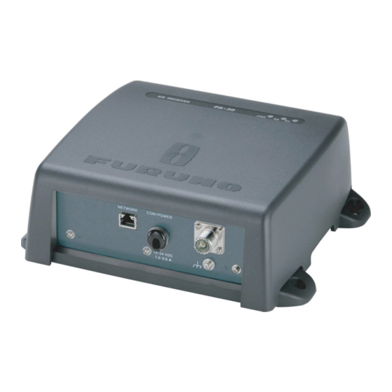
Page 10: Ais Receiver Fa-30
• Keep the unit away from electromagnetic field-generating equipment such as motors and gen- erators. • A magnetic compass will be affected if the FA-30 is placed too close to it. Observe the compass safe distances noted in the safety instructions to prevent disturbance to the magnetic compass. -
Page 11: Whip Antenna
10 meters. • Install the VHF whip antenna (option) referring to the outline drawing at the back of this manual. Separate this antenna from other VHF radiotelephone antennas as shown below to prevent interference to the FA-30. Other VHF whip antenna... -
Page 12: Wiring
Wiring Connect power source, LAN cable, VHF antenna and ground wire as shown below. VHF WHIP ANTENNA (option) COAXIAL CABLE 5D-2V (local supply) AIS RECEIVER GROUND WIRE PC, HUB, IV-1.25sq LAN CABLE NAVNET P5E-4PTX-BL (2 m or 10 m) POWER CABLE RS-422 RATING (supplied) NAVNET, SENSOR... - Page 13 Solder here. Connection with the PC and NavNet vx2 The FA-30 may be connnected to NavNet vx2, or to both NavNet vx2 and PC. See the figure below for connection examples. FA-30 RJ-45 to 6 Pin Cable NavNet vx2 display unit...
-
Page 14: Web Software Setup, Data Displays
DATA DISPLAYS AIS Receiver FA-30 The FA-30 has no power switch. Power is fed from the ship’s switchboard, and a power switch on the switchboard turns the FA-30 on or off. When powered, the PWR LED (green) on the cover lights. -
Page 15: Com Port Setup, Network Setup
COM Port Setup, Network Setup The FA-30 is set up from the PC or external display. The procedure below shows how to set up the COM/POWER and NETWORK ports from a PC. NOTICE: Only one FA-30 may be connected to the network. - Page 16 ® (Windows a) Left-click [setting] from the start menu. b) Left-click [Network & Internet]. c) Left-click [Change adapter options]. d) Right-click [Ethernet] and left-click [Properties]. e) Choose [Internet Protocol Version 4 (TCP/IPv4)] and left-click [Properties] button. f) Choose [Use the following IP address]. g) Enter IP address 172.31.24.xxx (xxx=any three digits from 001 to 254, except 002).
- Page 17 IEC61162+ P-sentence: Transmit and receive IEC61162+P sentences format data via COM port. Off: FA-30 transmits no data. With the radio buttons at RX Speed, choose how RX speed is regulated, Auto or Manual. For manual, choose speed from the drop-down list.
- Page 18 Do you want to restart your FA-30 now? (It will take about 1 minute to restart your FA-30). 18.Click the Yes button to restart. "ER" LED on the FA-30 lights. After the LED goes off access is given. 19.The message “Please close the window.” appears. Close the browser.
-
Page 19: Own Vessel Data Display, Channel Selection
Own Vessel Data Display, Channel Selection The Own Vessel Data display shows your ship’s MMSI no., RX channel nos., and channel selec- tion method. 1. Show the main menu, referring to section 2.2. 2. Click Own Vessel Data. CH. 2087 (International) CH. - Page 20 5. Click the RX Mode drop-down list to choose which channel(s) to receive. RX 1+2 RX 1+2 RX 1 RX 2 RX 1+2: Receive via channels 1 and 2. RX 1: Receive via channel 1. RX 2: Receive via channel 2. 6.
-
Page 21: Sensor Status
Sensor Status The sensor status display provides information about sensors connected to the FA-30. 1. Show the main menu, referring to section 2.2. 2. Click Sensor Status. The illustration below shows typical sensor status indications. GPS in use Heading valid... -
Page 22: Maintenance, Troubleshooting
MAINTENANCE, TROUBLESHOOTING WARNING NOTICE Do not open the equipment Do not apply paint, anti-corrosive unless totally familiar with sealant or contact spray to coating or electrical circuits and plastic parts of the equipment. service manual. Those items contain organic solvents that Only qualified personnel can damage coating and plastic parts, should work inside the... -
Page 23: Replacing The Fuse
PWR (power) LED is off, the fuse may have blown. If this happens, turn off the power to the FA-30, open the cover and check the fuse. If the fuse has blown, find out the reason before replacing it. -
Page 24: Diagnostics
Diagnostics The built-in diagnostic facility displays program version no. and checks RAM, ROM and RX chan- nels for proper operation. 1. Open Internet Explorer and show the main menu. 2. Click Test to show the Test display. 0550227-xx.xx* *xx.xx is program version. The program version number appears on the first line. -
Page 25: Appendix 1: Vhf Channel List
Appendix 1: VHF CHANNEL LIST Ch No. Frequency Ch No. Frequency Ch No. Frequency Ch No. Frequency 1001 156.05 1088 157.425 156.8875 2079 161.575 1002 156.1 1201 156.0625 1278 156.9375 2080 161.625 1003 156.15 1202 156.1125 1279 156.9875 2081 161.675 1004 156.2 1203... -
Page 26: Appendix 2: Mounting Vhf Splitter
Appendix 2: MOUNTING VHF SPLITTER The VHF splitter enables the AIS receiver and VHF transceiver to share a single VHF antenna. Note: The FA-30 can not receive AIS signal when the VHF transceiver is transmitting. Equipment Lists VHF Splitter: Type OP05-106, Code No. 000-011-704... - Page 27 4. Turn over the chassis. Then, disconnect mini coaxial wire from J2 on pcb 05P0808A. 05P8080A Hole 4. Disconnect mini coaxial wire. Bottom view 5. Unfasten four screws from the rear panel to come free. 5. Unfasten four screws. Rear panel 6.
- Page 28 15.Connect the coaxial cable from the VHF antenna to the ANT port. 16.Connect the coaxial cable from the VHF transceiver to the VHF port. Note: The wrong connection of coaxial cable from VHF antenna or VHF transceiver may damage this equipment. VHF antenna FA-30 05P0808A 05P0187 05P0808B VHF transceiver...
-
Page 29: Specifications
FURUNO FA-30 SPECIFICATIONS OF AIS RECEIVER FA-30 GENERAL Rx capacity 2250 reports/minute, 1 channel 4500 reports/minute, 2 channels Rx system TDMA dual wave simultaneous reception Frequency switching Automatic (external device) Complying regulations IEC 60945 Ed. 4, and receiver section conforms to IEC 61993-2, IEC 62287-1, ITU-R M.1371-1... - Page 30 FURUNO FA-30 INTERFACE COM port Input signal RS422(38.4kbps)/IEC61162-1(4800 bps) Input sentences ACK, ACA, AIQ, DSC, DSE, DTM, GBS, GGA, GLL, GNS, HDT, OSD, PFEC, RMC, VBW, VTG, ZDA, ABM*, BBM*, AIR* Output signal RS422(38.4kbps) Output sentences ACA, ACS, ALR, PFEC, VDM, VDO, TXT, ABK*...
- Page 31 Input power 0.5-25W Coupling factor 1dB or less Decoupling factor 25dB or more Maximum power 30W (50 ohms) nominal Power detection 500mW or more Detection time Within 10ms Power source 11.0VDC±10%, within 1.5W, supplied by receiver unit FA-30 SP-3 E4443S01C 070907...
- Page 37 When a claim is made, FURUNO has a right to choose whether with other electronic devices. The imported product may also be to repair the product or replace it.
- Page 38 24 months from installation date provided the work is done by Furuno U.S.A., Inc. or an AUTHORIZED Furuno dealer during normal shop hours and within a radius of 50 miles of the shop location.
- Page 39 Цялостният текст на ЕС декларацията за съответствие може да се намери на следния интернет адрес: Spanish Por la presente, Furuno Electric Co., Ltd. declara que el tipo de equipo radioeléctrico arriba mencionado es conforme con la Directiva 2014/53/UE. (ES) El texto completo de la declaración UE de conformidad está disponible en la dirección Internet siguiente:...
- Page 40 Az EU-megfelelőségi nyilatkozat teljes szövege elérhető a következő internetes címen: Maltese B'dan, Furuno Electric Co., Ltd., niddikjara li msemmija hawn fuq-tip ta' tag mir tar-radju huwa konformi mad-Direttiva 2014/53/UE. (MT) It-test kollu tad-dikjarazzjoni ta' konformità tal-UE huwa disponibbli f'dan l-indirizz...
Need help?
Do you have a question about the FA-30 and is the answer not in the manual?
Questions and answers