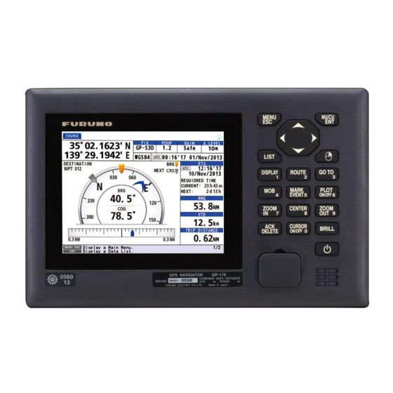
Furuno GP-170 Installation Manual
Hide thumbs
Also See for GP-170:
- Operator's manual (117 pages) ,
- Installation manual (67 pages) ,
- Installation manual (68 pages)
Advertisement
Quick Links
This information provides the procedure for the installation of the DGPS/DGLONASS Beacon Re-
ceiver in the GP-170. The installation mainly consists of mounting the Beacon Antenna and the
DGPS/DGLONASS Beacon Receiver, and connecting the cable assembly.
For how to mount the antenna unit, refer to the GP-170 installation manual.
Beacon Receiver Set
The contents of the Beacon Receiver Set are shown in the table below.
For GPA-021S (DGPS antenna)
For GPA-023S (DGPS/DGLONASS antenna)
Name
Antenna Unit
BEACON PCB
PH Connector Assy.
Connector Assy.
Binding Head Screw
Beacon Receiver Manual
Overview
The parts shown with dotted lines are added and connected as shown below.
MAIN Board
20P8209
J14
J12
GNSS NAVIGATOR GP-170
DGPS/DGLONASS Beacon Receiver
Type: OP20-42
Type
GPA-021S
GPA-023S
20P8208A(LF)
20-070(9-6,3P)
U.FL-2LP-068N1T-A150
M3x6
C42-01306
LCD
J10
J11
CN1
CN2
J7
CN3
J8
Interconnection diagram after the installation
www.furuno.com
Installation Manual
Code No.: 000-027-033
Type: OP20-55
Code No.: 000-037-892
001-331-600
000-037-840
001-302-340
001-334-850
000-177-900-10
000-176-673-10
000-190-251-1x
PNL Board
J1
20P8210
J2
GPS Board
20P8211
J2
J1
BEACON PCB
20P8208A(LF)
J2
J4
J3
J1
Code No.
Qty
1
1
1
1
1
1
UFL_ANT
Board
20P8220
J1
Advertisement

Summary of Contents for Furuno GP-170
- Page 1 Installation Manual This information provides the procedure for the installation of the DGPS/DGLONASS Beacon Re- ceiver in the GP-170. The installation mainly consists of mounting the Beacon Antenna and the DGPS/DGLONASS Beacon Receiver, and connecting the cable assembly. For how to mount the antenna unit, refer to the GP-170 installation manual.
- Page 2 Procedure Disconnect the cables connected at the rear of the display unit. Remove the display unit from the hanger. Display Unit Knob Knob Hanger Unfasten each nut attached to the connectors at the rear of the display unit. Unfasten the six screws at the rear of the display unit. Screw Disconnect the PH connector assembly from J7 on the MAIN board 20P8209.
- Page 3 Disconnect the coaxial cable from J1 on the UFL_ANT board 20P8220 and detach it from the cable clamp. Also, remove the tape from the cover assembly. NOTE1: Do not discard the tape because it is used again at step 19. NOTE2: It is recommended to use the following tool (or equivalent) to disconnect the coaxial cable.
- Page 4 15. Fix the two coaxial cables with the cable clamp. Binding Head Screw (M3x6) Turn over. Cable Clamp 16. Turn the mated assembly over. 17. Connect the PH connector assembly 20-070(9-6,3P) supplied to J3 and J4 on the BEACON PCB 20P8208A(LF).
- Page 5 21. Connect the PH connector assembly connected to the BEACON PCB 20P8208A(LF) to J8 on the MAIN board 20P8209. BEACON PCB 20P8208A(LF) MAIN Board 20P8209 Panel Assembly Cover Assembly GPS Board 20P8211 22. Attach the panel assembly to the cover assembly. 23.
- Page 6 This page is intentionally left blank.
- Page 7 こ のページは空白です。...
- Page 8 MAIN 基板 20P8209 の J8 に、 BEACON プ リ ン ト 20P8208A(LF) か らの PH コ ネ ク タ 組品を接続 し ま す。 カバー組品 と パネル組品を組み立て ます。 手順 4 の図を参照 し て、 以下の手順を行います。 ・手順 3 で外 し た、 本体背面の コ ネ ク タ 用の各ナ ッ ト すべて を取 り 付け ます。 ・手順...
- Page 9 2 本の同軸ケーブルを ケーブル ク ラ ン プに固定 し ます。 手順 15 で 2 本の同軸ケーブルを固定 し た後、 その組品を裏返 し ます。 BEACON プ リ ン ト 20P8208A(LF) の J3 と J4 に、 キ ッ ト で支給の PH コ ネ ク タ 組品 20-070(9-6,3P) を 接続...
- Page 10 UFL_ANT 基板 20P8220 の J1 と ケーブル ク ラ ン プか ら、 同軸ケーブルを外 し ます。 また、 ポ リ エ ス パーテープ もはが し ます。 注 1) ポリエスパーテープは再利用するので、捨てないでください。 注 2) 同軸コネクタを抜くときは、以下の引抜き用治具(現地手配)の使用を推奨します。 メーカー 品名 番号 ヒ ロ セ電機 U.FL-LP-N-2 331-0494-5 カバー組品か ら ネジ 2 本を外 し て、 GPS 組品を外 し ます。 GPS 基板...
- Page 11 手順 受信演算部の背面で、 接続 さ れてい る ケーブルを外 し ます。 受信演算部か らハン ガーを外 し ます。 受信演算部背面にあ る、 コ ネ ク タ の各ナ ッ ト をすべて外 し ます。 背面で 6 本のネジ を外 し ます。 MAIN 基板 20P8209 の J7 に接続 さ れてい る、 PH コ ネ ク タ 組品を外 し ます。 カバー組品をパネル組品か...
- Page 12 衛星航法装置 GP-170 DGPS/DGLONASS ビー コ ン受信部組込み説明書 こ の小冊子は、 衛星航法装置 GP-170 を DGPS/DGLONASS 航法装置にす る ための改造要領で す。 GP-170 に DGPS/DGLONASS 用ビー コ ン受信機を組み込むための手順について、 説明 し ま す。 空中線部の装備については、 装備要領書を参照 し て く だ さ い。 ビー コ ン内蔵キ ッ ト ビー コ ン内蔵キ ッ ト の構成は、 以下の通 り です。...


Need help?
Do you have a question about the GP-170 and is the answer not in the manual?
Questions and answers