Table of Contents
Advertisement
K1G Series High-Accuracy Position Sensor
User's Manual
There are nine different manuals related to the K1G
series. Read them as necessary for your specific
requirements. (
P. iii )
Photo of K1G-S07
This user's manual is for instrumentation that uses the K1G
series' K1G-C04, K1G-C04M, and K1G-C04E controllers.
For CE- and KC-marked K1G-C04G, K1G-C04MG, and K1G-
C04EG controllers, please refer to K1G Series High-Accuracy
Position Sensor Global Model User's Manual (CP-SP-1397E) .
IntrodUctIon
WHAt to KnoW BEForE USE
InStALLAtIon And WIrInG
InItIAL SEtUP
AdVAncEd SEttInGS
coMMUnIcAtIon SEttInGS
(connEctIon to otHEr dEVIcES)
SZ-d01 conFIGUrAtIon tooL
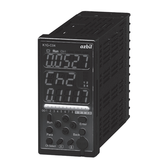
Photo of K1G-C04
SPEcIFIcAtIonS
troUBLE SHootInG
APPEndIX
No. CP-SP-1385E
1
2
3
4
5
6
7
8
9
Advertisement
Table of Contents
Troubleshooting

Related Manuals for Azbil K1G Series


Summary of Contents for Azbil K1G Series
- Page 1 This user's manual is for instrumentation that uses the K1G troUBLE SHootInG series' K1G-C04, K1G-C04M, and K1G-C04E controllers. For CE- and KC-marked K1G-C04G, K1G-C04MG, and K1G- C04EG controllers, please refer to K1G Series High-Accuracy APPEndIX Position Sensor Global Model User's Manual (CP-SP-1397E) .
- Page 2 If you should find an error or omission, please contact the azbil Group. In no event is Azbil Corporation liable to anyone for any indirect, special or consequential damages as a result of using this product. © 2015-2018 Azbil Corporation All Rights Reserved.
- Page 3 SAFEty PrEcAUtIonS The safety precautions explained in the following section aim to prevent injury to the operator and others, and to prevent property damage. Warnings are indicated when mishandling this product WArnInG might result in death or serious injury. Cautions are indicated when mishandling this product might result cAUtIon in minor injury to the user, or physical damage to the product.
- Page 4 WArnInG Do not use unused terminals on the device as relay terminals. Doing so may re- sult in electric shock, fire or device failure. In the following cases, turn off the power immediately and stop using the device. • If the device gets wet (with water or another liquid). •...
- Page 5 MAnUAL A total of 9 different manuals are available for the K1G series. Read them as necessary for your specific requirements. If a manual you require is not available, contact the Azbil Group or its dealer.
- Page 6 Attachment Instructions for Ferrite core and Shielded Junction cables for K1G Series High-Accuracy Position Sensors Manual no. cP-UM-5810JE Please read this manual if you use a CE- or KC-marked global model of the K1G series. This manual covers safety precautions, installation, and wiring.
- Page 7 Introduction Thank you for purchasing this Azbil Corporation product. This manual contains informa- tion for ensuring the safe and correct use of the product. It should be read by those who design or maintain a control panel or other equipment that uses this product.
- Page 8 Consider the combination carefully before use. • If electromagnetic interference caused by this device affects other devices, use a shielded junction cable. For details, contact the azbil Group. InStALLAtIon EnVIronMEnt To ensure the safe and correct use of the product, do not install it where it will be ex- posed to any of the following: •...
- Page 9 PrEcAUtIonS For WIrInG WArnInG Before mounting, removing, or wiring, be sure to turn off the power to this de- vice and all connected devices. Failure to do so may result in electric shock. Be sure to check that the device has been correctly wired before turning on the power.
- Page 10 cABLES For tHE K1G Use JCS4364-compliant instrument cable or equivalents for K1G-C04 inputs and outputs (twisted shielded instrument cable). The following cables are recommended. Fujikura Ltd. 2 cores IPEV-S-0.9 mm ×1P 3 cores ITEV-S-0.9 mm ×1T Hitachi Metals, Ltd. 2 cores KPEV-S-0.9 mm ×1P 3 cores KTEV-S-0.9 mm...
- Page 11 tErMInAL connEctIon WArnInG Firmly tighten the terminal screws to a torque of 0.4–0.6 N·m. If tightening is insufficient there is a risk of electric shock or fire. Do not use unused terminals on the device as relay terminals. Doing so may re- sult in electrical shock, fire or device failure For controller connections, use crimp terminals compatible with M3 screws.
- Page 12 WIrInG oF tHE PoWEr And GroUnd WArnInG Before mounting, removing, or wiring, be sure to turn off the power to this de- vice and all connected devices. Failure to do so may result in electric shock. The power supply rating for this device is 12–24 V DC. Do not apply 100–240 V AC. Doing so may cause device failure or fire.
- Page 13 PoWEr-on rESEt The device begins making measurements about one second after the power has been turned on. After the output response time has passed, analog output (AO) or digital output (DO) begins. A request to establish a MECHATROLINK-III communications connection can be accepted about one second after the power has been turned on.
-
Page 14: Table Of Contents
1. WHAt to KnoW BEForE USE ....1-1 1-1 About the K1G Series .......... - Page 15 4-8 Other Functions 4-96 ............4-9 Changing MECHATROLINK-III Communication Settings 4-108 .
- Page 16 MEMO ✎...
-
Page 17: Chapter 1. What To Know Before Use
WHAt to KnoW BEForE USE This chapter gives an overview of K1G series sensors and the names and functions of their parts. 1-1 About the K1G Series ........ -
Page 18: About The K1G Series
1-1 About the K1G Series SyStEM conFIGUrAtIon The K1G series features a semiconductor laser emitter and a receiver with a line image sensor. These two sensor heads measure the position of a workpiece that is between them. ● If K1G-C04 is used... - Page 19 1-1 About the K1G Series EXAMPLES oF K1G MEASUrEMEntS Determining edge position Sensing the edge's status Edge measurement Edge width measurement Transparent Opaque Transparent objects objects objects Received light pro le Received light pro le Emitter Emitter Light-receiving Light-receiving cell...
-
Page 20: Check Of Included Items
1-2 check of Included Items SEnSor HEAdS K1G-S07 K1G-S15 Model No. Model No. (measurement width: 7 mm) (measurement width: 15 mm) Emitter (1) Emitter (1) Receiver (1) Receiver (1) FDA label (1) FDA label (1) User's manual, No. CP-UM-5784JE User's manual, No. CP-UM-5784JE Note: This product has been registered with the FDA (CDRH). - Page 21 1-2 check of Included Items K1G-C04E (for 4 channels) Model No. Sensor head cable (1) Controller User's manual, No. CP-UM-5910JE Mounting brackets (2) SZ-E02 Ferrite Core (2) User's manual, No. CP-UM-5916JE...
- Page 22 1-2 check of Included Items JUnctIon cABLE Necessary for connection of the sensor head cable to the sensor heads. The standard model or bend-tolerant model can be selected according to the installa- tion conditions. Shielded cables are also available. K1G-L _ _ K1G-L _ _ S: Model No.
-
Page 23: Optional Parts
1-3 optional Parts Front PAnEL ProtEctIVE coVEr For controLLErS This cover protects the controller front panel and prevents operator errors. It can be opened and closed. 81441421-001 Model No. noISE FILtEr If there is a considerable amount of electrical noise from the power supply, a noise filter is used in combination with an isolation transformer. - Page 24 1-3 optional Parts K1G conFIGUrAtIon tooL This tool especially made for the K1G series is used for setup, parameter configuration, and monitoring. SZ-D01 Model No. Display unit (5.7 inches) Stand Con guration device with touch panel. Used for installation of the display unit.
-
Page 25: Names And Functions Of Parts
1-4 names and Functions of Parts SEnSor HEAdS Handling Precautions • Be sure that the emitter and receiver have the same serial number. If an emitter and receiver with different numbers are used, the product may not meet the listed specifications. Emitter Receiver Example: K1G-S15... - Page 26 1-4 names and Functions of Parts controLLEr Front K1G-C04 Run Ch1 Ch2 Ch3 Ch4 Hold 1 2 3 4 DI DO 1 2 3 4 5 6 7 8 Enter Back Para Ch Select Name Description Run Ch1 Ch2 Ch3 Ch4 Operation and channel indicators Lit to indicate which channel's mea-...
- Page 27 1-4 names and Functions of Parts Name Description Display 2 Displays the measured value. Status indicators Indicate the operating status of the channel selected for display 1. Lit when the status of the measured value is "Hold." Lit when the max. digital input (DI) constant output function is used.
- Page 28 1-4 names and Functions of Parts Back K1G-C04 K1G-C04M K1G-C04E Name Description Sensor head cable connector Connects the included sensor head cable and controller. Terminals Used for wiring of the power and input/output signal wires. LEDs for MECHATROLINK-III LK1 (link 1, green): Lit when link CN1 is estab- lished LK1 (link 2, green): Lit when link CN2 is estab- lished...
- Page 29 1-4 names and Functions of Parts Name Description RJ45 port Connects the network cable for EtherCAT com- munication. ECAT OUT: EtherCAT communica- tion OUT port Link/ Activity LED ECAT IN: EtherCAT communica- tion IN port Link/Activity indicator: Green Shows the state of the EtherCAT communica- tion port physical link and data transmission.
- Page 30 1-4 names and Functions of Parts dEtAILS on EtHErcAt IndIcAtorS Types of indicator states Indicator states Definition Constantly OFF Flickering ON for 50 ms and OFF for 50 ms Blinking ON for 200 ms and OFF for 200 ms Single Flashes ON for 200 ms and OFF for 1000 ms Double Flashes ON for 200 ms and OFF for 200 ms and ON for 200 ms and OFF for 1000 ms...
-
Page 31: Chapter 2. Installation And Wiring
InStALLAtIon And WIrInG This chapter describes installation and wiring of the sensor heads and controller. 2-1 Installing the Sensor Heads ......2-2 Install the controller in the panel. -
Page 32: Installing The Sensor Heads
2-1 Installing the Sensor Heads SAFEty PrEcAUtIonS WArnInG Do not do work while power is supplied. There is a risk of electric shock or device failure. Do not use this device in atmospheres containing corrosive or flammable gas, liquids, or powder. cAUtIon Take care that cables are not pinched or caught on something. -
Page 33: Install The Controller In The Panel
2-2 Install the controller in the panel. Make a cutout in the panel The controller is a panel-mount type. Make a cutout in the panel according to the following dimensions. Individual mounting Gang-mounting Unit: mm +0.5 +0.5 50 min. (48xN−4) Note: N represents the number of controllers. Handling Precautions •... - Page 34 2-2 Install the controller in the panel. Attach the mounting brackets Attach the included mounting brackets to the top and bottom of the controller. Attach the bottom bracket first. Mounting bracket (included) Panel 10° max. Panel thickness: 7 mm max. Tighten the screws Tighten the screws of the mounting brackets until there is no more play be- tween the bracket and screw and panel, and then turn one revolution more only.
-
Page 35: Connecting The Sensor Heads
2-3 connecting the Sensor Heads Attach the cables Precautions for wiring • Secure the cable in a way that avoids stress where it exits the device and near the connector. ● Sensor head cable ● Sensor head cable Cable length: 0.4 m Connector type: Socket (panel-mount) -
Page 36: Wiring The Controller (K1G-C04)
2-4 Wiring the controller (K1G-c04) tErMInAL LAyoUt 1 Power + AO1 + Power - AO1 - AO2 + AO2 - AO3 + AO3 - AO4 + (Empty) AO4 - Sensor head cable connector (Empty) Handling Precautions • Be sure to check that the module has been correctly wired before turning on the power. Mistakes in wiring can damage the device. - Page 37 2-4 Wiring the controller (K1G-c04) WIrInG oF dIGItAL oUtPUt (do) When NPN is selected When PNP is selected Power + Power + − − Power - Power - Load Load Load Load Load Load Load Load Load Load Load Load Load Load Load...
- Page 38 2-4 Wiring the controller (K1G-c04) WIrInG oF dIGItAL InPUt (dI) When NPN is selected When PNP is selected Power + Power + − − Power - Power - Input circuit 12–24 V DC +5 V NPN: 0 V PNP: 12–24 V DC Handling Precautions •...
- Page 39 2-4 Wiring the controller (K1G-c04) WIrInG oF AnALoG oUtPUt (Ao) 1–5 V / 4–20 mA AO1 + Analog input device AO1- 1–5 V / 4–20 mA AO2 + Analog input device AO2- 1–5 V / 4–20 mA AO3 + Analog input device AO3- 1–5 V / 4–20 mA AO4 +...
- Page 40 2-4 Wiring the controller (K1G-c04) rS-485 coMMUnIcAtIonS ● If devices with 3-wire and 5-wire systems are both used K1G or device with a 3-wire system (slave station) Terminating resistor Host station Shielded Shielded 5-wire device (slave station) Shielded 5-wire device (slave station) Terminating resistor 2-10...
- Page 41 2-4 Wiring the controller (K1G-c04) ● When only devices with a 3-wire system are used K1G or device with a 3-wire system (slave station) Terminating resistor Host station Shielded Shielded K1G or device with a 3-wire system (slave station) Shielded K1G or device with a 3-wire system (slave station) Terminating resistor...
-
Page 42: Wiring The Controller (K1G-C04M)
2-5 Wiring the controller (K1G-c04M) tErMInAL LAyoUt Sensor head cable connector Power supply MECHATROLINK-III Power + Connector 1 Power - Connector 2 Handling Precautions • Be sure to check that the module has been correctly wired before turning on the power. Mistakes in wiring can damage the device. 2-12... -
Page 43: Wiring The Controller (K1G-C04E)
2-6 Wiring the controller (K1G-c04E) tErMInAL LAyoUt Sensor head cable connector Power supply EtherCAT Power + ECAT OUT Power - ECAT IN Handling Precautions • Be sure to check that the module has been correctly wired before turning on the power. Mistakes in wiring can damage the device. - Page 44 2-6 Wiring the controller (K1G-c04E) WIrInG MEtHod To use the K1G-C04E properly, be sure to follow the wiring method described below. ● Power cable and sensor head cable • Attach the ferrite cores (included) to the power wires of the controller (not in- cluded).
- Page 45 2-6 Wiring the controller (K1G-c04E) ● Communication cable • Use a double-shielded cable (not included) for communication. • Remove the jacket at both ends and ground the shield using a cable clamp (not included). Remove the jacket at both ends and K1G-C04E ground the shield using a cable clamp.
- Page 46 MEMO ✎...
-
Page 47: Chapter 3. Initial Setup
InItIAL SEtUP The chapter describes the initial setup after the power to the controller has been turned on for the first time. Initial Setup Flowchart ..............3-1 Analog Output (AO) Settings . -
Page 48: Initial Setup Flowchart
Initial Setup Flowchart K1G-C04 K1G-C04M K1G-C04E Before power-on Power-on Power-on <First time only> <If necessary> <Can be done at any time Set the analog Set the station address Set the ECAT ID. output (AO) for MECHATROLINK-III. P. 3-3 P. 3-5 P. -
Page 49: Analog Output (Ao) Settings
3-1 Analog output (Ao) Settings Set the analog output (AO) (for K1G-C04) 2 3 4 Power-on Start of operation Analog output settings applies to all channels. The parameters cannot be changed for individual channels. Select the output method Display Select vOLt or CRNT using K1G-C04 Run Ch1 Ch2 Ch3 Ch4 Parameter... -
Page 50: Digital Input/Output (Di/Do) Settings
3-2 digital Input/output (dI/do) Settings Set the digital input and output (DI/DO) (for K1G-C04) Power-on Start of operation The digital input/output applies to all channels. The parameters cannot be changed for individual channels. Select the input/output method Display Select NPN or PnP using K1G-C04 Run Ch1 Ch2 Ch3 Ch4 Parameter... -
Page 51: Setting The Station Address For Mechatrolink-Iii
3-3 Setting the Station Address for MEcHAtroLInK-III Set the station address (for K1G-C04M) 2 3 4 Power-on Start of operation Select the station address. Display Select the station address using K1G-C04 Run Ch1 Ch2 Ch3 Ch4 Parameter Description Hold 3H to EFH Station address DO 1 2 3 4 5 6 7 8 1 2 3 4 DI Enter... -
Page 52: Setting The Number Of Transmission Bytes For Mechatrolink-Iii
3-4 Setting the number of transmission Bytes for MEcHAtroLInK-III Set the number of transmission bytes (for K1G-C04M) Power-on Start of operation Select the number of transmission bytes Display Choose 48 or 32 using K1G-C04 Run Ch1 Ch2 Ch3 Ch4 Parameter Description Hold No. -
Page 53: Setting The Measurement Cycle
3-5 Setting the Measurement cycle Set the measurement cycle Power-on Start of operation The measurement cycle applies to all channels. This parameter cannot be changed for individual channels. Select the parameter Display Select 250u, 500u, or 1000u, using K1G-C04 Run Ch1 Ch2 Ch3 Ch4 Parameter Description Hold... -
Page 54: Receiver Adjustment
3-6 receiver adjustment Adjust the receiver Power-on Start of operation Handling Precautions • Make sure that there is no workpiece before starting. • If the laser beam emitting surface or receiving surface is dirty, beam alignment and intensity adjustment cannot be done correctly. •... - Page 55 3-6 receiver adjustment The beam is not aligned (receiver adjustment is not possible). Check the emitter and receiver positions, and the beam angle. The light intensity at the receiver is insufficient. The laser beam is offset to the bottom side (B) of the receiver.
- Page 56 K1G-C04 3-6 receiver adjustment Run Ch1 Ch2 Ch3 Ch4 Hold Complete the adjustments Press for at least 3 seconds to end the DO 1 2 3 4 5 6 7 8 1 2 3 4 DI Enter adjustment. Back Para Ch Select KG-C04 Run CH1 CH2 CH3 CH4...
-
Page 57: Setting The Ecat Id (For K1G-C04E Only)
3-7 Setting the EcAt Id (for K1G-c04E only) ECAT ID setup (K1G-C04E) Before 2 3 4 Start of operation power-on Set the ID using the ECAT ID setting switches Change the settings using a screwdriver (factory default: 00) Parameter Description ECAT ID is not used 01 to FF The set value is used as the ECAT ID... - Page 58 MEMO ✎...
-
Page 59: Chapter 4. Advanced Settings
AdVAncEd SEttInGS This chapter describes various functions of the K1G series. As needed, the settings should be changed. 4-1 Settings that Can Be Changed ........ -
Page 60: Settings That Can Be Changed
4-1 Settings that can Be changed cHAnGInG tHE InItIAL SEttInGS To change the initial settings configured in chapter 3, see the pages indicated below. Changing the display Changing DI/DO and AO operation Changing the display type P. 4-5 Changing the DI settings P. - Page 61 4-1 Settings that can Be changed Changing the AO range Changing the analog output (AO) range ... . ( P. 4-25 ) Changing the measurement zero adjustment value . ( P.
- Page 62 4-1 Settings that can Be changed HoW to SWItcH BEtWEEn rUn/rEAdy ModES ● How to check the current mode To learn the current mode, check the operation indicator. If the LED is lit, the mode is "Run" (measuring). K1G-C04 Run Ch1 Ch2 Ch3 Ch4 Hold On the following pages, in order to indicate which mode allows a setting change, one of the following...
-
Page 63: Changing The Display
4-2 changing the display cHAnGInG tHE tyPE oF dISPLAy The contents of the display while the controller is in Run mode can be se- lected according to the intended use. There are four display types for the K1G-C04, and five types for the K1G-C04M and K1G-C04E. K1G-C04 Run Ch1 Ch2 Ch3 Ch4 Display 1... - Page 64 4-2 changing the display Standard Display 1 shows the measured value from the selected channel. The auxiliary display shows the channel number of other channels, and display 2 shows measured values from these channels. If there are several unselected channels, the channels and measured values are switched automatically every 2 seconds.
- Page 65 When connected, “Con” is displayed. When dis- connected, “---” is displayed. Display 2 shows the error status of MECHATORLINK-Ш communication. For details on the error status, refer to K1G Series High-Accuracy Position Sensor MECHATROLINK-III Communication Manual (No. CP-SP-1386E). EtherCAT communication status check display (for K1G-C04E only) Display 1 shows the measured value from the selected channel.
- Page 66 4-2 changing the display cHAnGInG tHE dISPLAy rESoLUtIon Ready Ready Changes the display of digits after the decimal point. The display resolution applies to all channels. This parameter cannot be changed for each channel. Procedure Procedure Check that the mode is "Ready" K1G-C04 If "Run"...
- Page 67 K1G-C04 4-2 changing the display Run Ch1 Ch2 Ch3 Ch4 Hold Enter A02 to finalize your selection of A02. Press DO 1 2 3 4 5 6 7 8 1 2 3 4 DI Enter Enter Enter Enter Back Para Ch Select K1G-C04 Run Ch1 Ch2 Ch3 Ch4...
- Page 68 4-2 changing the display KG-C04 Run CH1 CH2 CH3 CH4 Hold Exit the display for changing settings Press DO 1 2 3 4 5 6 7 8 1 2 3 4 DI Back Back Back Enter Back Para Ch Select K1G-C04 Run Ch1 Ch2 Ch3 Ch4 Hold...
-
Page 69: Changing The Measurement Settings
4-3 changing the Measurement Settings cHAnGInG tHE MEASUrEMEnt ModE Ready Ready The measurement mode can be Measurement mode Object type Measurement orientation selected from ten types accord- Edge measure- Opaque ing to the object type, the appli- ment object Bottom Transparent cation, and the object's direction object... - Page 70 4-3 changing the Measurement Settings Procedure Procedure Check that the mode is "Ready" K1G-C04 If "Run" is lit, press for 3 seconds or longer, and then check Run Not lit Ch1 Ch2 Ch3 Ch4 that "Run" is not lit (= Ready mode). Hold DO 1 2 3 4 5 6 7 8 1 2 3 4 DI...
- Page 71 K1G-C04 4-3 changing the Measurement Settings Run Ch1 Ch2 Ch3 Ch4 Hold Enter B02 to finalize your selection of B02. Press DO 1 2 3 4 5 6 7 8 1 2 3 4 DI Enter Enter Enter Enter Back Para Ch Select K1G-C04...
- Page 72 4-3 changing the Measurement Settings KG-C04 Run CH1 CH2 CH3 CH4 Hold Exit the display for changing settings Press DO 1 2 3 4 5 6 7 8 1 2 3 4 DI Back Back Back Enter Back Para Ch Select K1G-C04 Run Ch1 Ch2 Ch3 Ch4 Hold...
- Page 73 4-3 changing the Measurement Settings cHAnGInG tHE MEASUrEMEnt cycLE Ready Ready The measurement cycle applies to all channels. This parameter cannot be changed for each channel. Procedure Procedure Check that the mode is "Ready" If "Run" is lit, press for 3 seconds or longer, and then check K1G-C04 Run Not lit Ch1 Ch2 Ch3 Ch4...
- Page 74 K1G-C04 4-3 changing the Measurement Settings Run Ch1 Ch2 Ch3 Ch4 Hold Select the parameter Select one of the following by pressing DO 1 2 3 4 5 6 7 8 1 2 3 4 DI Enter Parameter Description Default setting Back Para 250u...
- Page 75 4-3 changing the Measurement Settings K1G-C04 Run Ch1 Ch2 Ch3 Ch4 Hold Start measuring To start measuring, press for 3 seconds or longer. DO 1 2 3 4 5 6 7 8 1 2 3 4 DI Enter Back Para Ch Select KG-C04 Run CH1 CH2 CH3 CH4...
- Page 76 4-3 changing the Measurement Settings cHAnGInG tHE no. oF MoVInG AVErAGES Ready Ready A moving average is calculated from the measured data. If more moving averages are calculated, the measurements become more reliable, but the response becomes slower. Procedure Procedure Check that the mode is "Ready"...
- Page 77 4-3 changing the Measurement Settings KG-C04 Run Ch1 Ch2 Ch3 Ch4 Hold Select B03 (number of moving averages) Display to select b01, and then press Press DO 1 2 3 4 5 6 7 8 1 2 3 4 DI select b03.
- Page 78 4-3 changing the Measurement Settings KG-C04 Run CH1 CH2 CH3 CH4 Hold Exit the display for changing settings Press DO 1 2 3 4 5 6 7 8 1 2 3 4 DI Back Back Back Enter Back Para Ch Select K1G-C04 Run Ch1 Ch2 Ch3 Ch4 Hold...
- Page 79 4-3 changing the Measurement Settings cHAnGInG tHE EdGE dEtEctIon tHrESHoLd Ready Ready The edge detection threshold is used to judge whether or not light is blocked. With the level of incoming light used for intensity adjustment as 100 %, if the amount of received light is less than the edge detection threshold, the light is judged to be blocked.
- Page 80 4-3 changing the Measurement Settings KG-C04 Run Ch1 Ch2 Ch3 Ch4 Hold Select the channel whose settings will be changed Select the channel No. by pressing Display DO 1 2 3 4 5 6 7 8 1 2 3 4 DI Ch2 Ch3 Ch4 Enter Ch Select...
- Page 81 K1G-C04 4-3 changing the Measurement Settings Run Ch1 Ch2 Ch3 Ch4 Hold Set the parameter to select a value from 5 to 95. Press DO 1 2 3 4 5 6 7 8 1 2 3 4 DI Enter Object type Back Para Parameter...
- Page 82 4-3 changing the Measurement Settings K1G-C04 Run Ch1 Ch2 Ch3 Ch4 Hold Start measuring To start measuring, press for 3 seconds or longer. DO 1 2 3 4 5 6 7 8 1 2 3 4 DI Enter Back Para Ch Select KG-C04 Run CH1 CH2 CH3 CH4...
-
Page 83: Changing The Analog Output (Ao) Settings
4-4 changing the Analog output (Ao) Settings cHAnGInG tHE AnALoG oUtPUt (Ao) rAnGE Ready Ready The analog output range can be changed. By using this function to narrow the measurement range, it is possible to obtain analog output with better resolution. The AO corresponds to changes in the measured value. Example of AO output range change (for K1G-S07) Current output (mA) Current output (mA) - Page 84 KG-C04 4-4 changing the Analog output (Ao) Settings Run Ch1 Ch2 Ch3 Ch4 Hold Switch to the display for changing settings Display Press DO 1 2 3 4 5 6 7 8 1 2 3 4 DI Para Enter Back Para Para Para...
- Page 85 4-4 changing the Analog output (Ao) Settings KG-C04 Run Ch1 Ch2 Ch3 Ch4 Hold Select C12 (analog output high limit) to select C12. Press DO 1 2 3 4 5 6 7 8 1 2 3 4 DI Enter Back Para Ch Select With K1G-S07 sensor...
- Page 86 4-4 changing the Analog output (Ao) Settings To change another setting, select the desired item by pressing KG-C04 Run CH1 CH2 CH3 CH4 Hold Exit the display for changing settings Press DO 1 2 3 4 5 6 7 8 1 2 3 4 DI Back Back Back...
- Page 87 4-4 changing the Analog output (Ao) Settings cHAnGInG tHE ZEro AdJUStMEnt VALUE Ready Ready This function configures the zero point of measurement. K1G-S07 (voltage output) K1G-S07 (voltage output) (zero adjustment value: 0.000 mm) (zero adjustment value: -1.000 mm) Measured value Output (mm ) (V )
- Page 88 KG-C04 4-4 Changing the Analog Output (AO) Settings Run Ch1 Ch2 Ch3 Ch4 Hold Switch to the display for changing settings Display Press DO 1 2 3 4 5 6 7 8 1 2 3 4 DI Para Enter Back Para Para Para...
- Page 89 4-4 changing the Analog output (Ao) Settings K1G-C04 Run Ch1 Ch2 Ch3 Ch4 Hold Finalize your parameter selection Press to finalize your parameter selection. DO 1 2 3 4 5 6 7 8 1 2 3 4 DI Enter Enter Enter Enter Back...
- Page 90 4-4 changing the Analog output (Ao) Settings KG-C04 Run CH1 CH2 CH3 CH4 Hold Choose whether to save the parameter Choose whether to save by pressing Display DO 1 2 3 4 5 6 7 8 1 2 3 4 DI Enter Back Para...
- Page 91 4-4 changing the Analog output (Ao) Settings SEttInG rEVErSE PoLArIty Ready Ready The analog output (AO) polarity can be reversed. AO polarity example (for K1G-S15) Positive polarity Negative polarity Current output (mA) Current output (mA) -7.5 -7.5 Measurement width (mm) Measurement width (mm) Procedure Procedure...
- Page 92 KG-C04 4-4 changing the Analog output (Ao) Settings Run Ch1 Ch2 Ch3 Ch4 Hold Switch to the display for changing settings Display Press DO 1 2 3 4 5 6 7 8 1 2 3 4 DI Para Enter Back Para Para Para...
- Page 93 4-4 changing the Analog output (Ao) Settings To change another setting, select the desired item by pressing KG-C04 Run CH1 CH2 CH3 CH4 Hold Exit the display for changing settings Press DO 1 2 3 4 5 6 7 8 1 2 3 4 DI Back Back Back...
- Page 94 4-5 Using digital Input (dI) and digital output (do) cHAnGInG dIGItAL InPUt (dI) SEttInGS Up to 4 digital inputs can be used. Channels and event types can be combined freely. DI operation type Operation Zero adjustment input When DI is turned ON, the zero point for measurement is changed.
- Page 95 4-5 Using digital Input (dI) and digital output (do) Procedure Procedure Ready Ready Check that the mode is "Ready" If "Run" is lit, press for 3 seconds or longer, and then check K1G-C04 Run Not lit Ch1 Ch2 Ch3 Ch4 that "Run"...
- Page 96 K1G-C04 4-5 Using digital Input (dI) and digital output (do) Run Ch1 Ch2 Ch3 Ch4 Hold Enter E09 to finalize your choice of E09. Press DO 1 2 3 4 5 6 7 8 1 2 3 4 DI Enter Enter Enter Enter...
- Page 97 4-5 Using digital Input (dI) and digital output (do) To change another setting, select the desired item by pressing KG-C04 Run CH1 CH2 CH3 CH4 Hold Exit the display for changing settings Press DO 1 2 3 4 5 6 7 8 1 2 3 4 DI Back Back Back...
- Page 98 4-5 Using digital Input (dI) and digital output (do) dIGItAL oUtPUtS (do) Up to 8 digital outputs can be used. Channels and event types can be combined freely. ● Using outputs during measurement DO operation Operation image Setting method type High Measured value Measured value...
- Page 99 4-5 Using digital Input (dI) and digital output (do) ● Using special outputs DO operation type Operation diagram Setting method Smudge detection P. 4-90 Function operation EPS event P. 4-83 DO operation DO operation "Hold" state P. 4-79 Normal operation Device status n the event of a con- Abnormal status...
- Page 100 4-5 Using digital Input (dI) and digital output (do) SEttInG tHE dIGItAL oUtPUt (do) oPErAtIon tyPE: HIGH/LoW/PASS/oUt Con guration owchart Con guration owchart Switch to Ready mode Select the DO No. Set DO1/3/5/7 Set DO2/4/6/8 Set the event source Set the event source [ E01 ] [ E05 ] Set the event type...
- Page 101 4-5 Using digital Input (dI) and digital output (do) Switch to Ready mode 1 2 3 4 5 6 7 8 9 Start Ready Procedure Procedure Ready Check that the mode is "Ready" If "Run" is lit, press for 3 seconds or longer, and then check K1G-C04 Run Not lit Ch1 Ch2 Ch3 Ch4...
- Page 102 4-5 Using digital Input (dI) and digital output (do) Set the event source 1 2 3 4 5 6 7 8 9 KG-C04 Start Run CH1 CH2 CH3 CH4 Hold Select E01 or E05 (event source) To select E01, Display DO 1 ...
- Page 103 K1G-C04 4-5 Using digital Input (dI) and digital output (do) Run Ch1 Ch2 Ch3 Ch4 Hold Finalize your parameter selection Press to finalize your parameter selection. DO 1 2 3 4 5 6 7 8 1 2 3 4 DI Enter Enter Enter...
- Page 104 K1G-C04 4-5 Using digital Input (dI) and digital output (do) Run Ch1 Ch2 Ch3 Ch4 Hold Finalize your parameter selection DO 1 2 3 4 5 6 7 8 1 2 3 4 DI Press to finalize your parameter selection. Enter Enter Enter...
- Page 105 K1G-C04 4-5 Using digital Input (dI) and digital output (do) Run Ch1 Ch2 Ch3 Ch4 Hold Select the parameter Select one of the following by pressing DO 1 2 3 4 5 6 7 8 1 2 3 4 DI Enter Parameter Description...
- Page 106 K1G-C04 4-5 Using digital Input (dI) and digital output (do) Run Ch1 Ch2 Ch3 Ch4 Hold Enter E04 (or E08) to finalize your choice of E04 or E08. DO 1 2 3 4 5 6 7 8 1 2 3 4 DI Press Enter Enter...
- Page 107 4-5 Using digital Input (dI) and digital output (do) Set the low threshold KG-C04 1 2 3 4 5 6 7 8 9 Run CH1 CH2 CH3 CH4 Start Hold Select C07 (low threshold) Display to select C01, and then press Press DO 1 2 3 4 5 6 7 8 1 2 3 4 DI to select C07.
- Page 108 4-5 Using digital Input (dI) and digital output (do) Set the high threshold KG-C04 Run Ch1 Ch2 Ch3 Ch4 1 2 3 4 5 6 7 8 9 Start Hold Select C08 (high threshold) Display to select C08. Press DO 1 2 3 4 5 6 7 8 1 2 3 4 DI Enter Back Para...
- Page 109 4-5 Using digital Input (dI) and digital output (do) Set the hysteresis KG-C04 Run Ch1 Ch2 Ch3 Ch4 1 2 3 4 5 6 7 8 9 Start Hold Select C09 (hysteresis) Display to select C09. Press DO 1 2 3 4 5 6 7 8 1 2 3 4 DI Enter Back Para...
- Page 110 4-5 Using digital Input (dI) and digital output (do) To change another setting, select the desired item by pressing KG-C04 Run CH1 CH2 CH3 CH4 Hold Exit the display for changing settings Press DO 1 2 3 4 5 6 7 8 1 2 3 4 DI Back Back Back...
-
Page 111: Using Digital Input (Di) And Digital Output (Do)
4-5 Using digital Input (dI) and digital output (do) AdVAncEd SEttInGS SEttInG SPEcIAL oUtPUtS Con guration owchart Con guration owchart 4-5 Using digital Switch to Ready mode Input (dI) and digi- tal output (do) Select the DO No. Set DO1/3/5/7 Set DO2/4/6/8 Set the event source Set the event source... - Page 112 4-5 Using digital Input (dI) and digital output (do) Switch to Ready mode 1 2 3 4 5 6 Start Ready Ready Procedure Procedure Check that the mode is "Ready" If "Run" is lit, press for 3 seconds or longer, and then check K1G-C04 Run Not lit Ch1 Ch2 Ch3 Ch4...
- Page 113 4-5 Using digital Input (dI) and digital output (do) Set the event source 1 2 3 4 5 6 Start KG-C04 Run CH1 CH2 CH3 CH4 Hold Select E01 or E05 (event source) To select E01, Display DO 1 2 3 4 5 6 7 8 1 2 3 4 DI KG-C04 press to display E01.
- Page 114 K1G-C04 4-5 Using digital Input (dI) and digital output (do) Run Ch1 Ch2 Ch3 Ch4 Hold Finalize your parameter selection Press to finalize your parameter selection. DO 1 2 3 4 5 6 7 8 1 2 3 4 DI Enter Enter Enter...
- Page 115 K1G-C04 4-5 Using digital Input (dI) and digital output (do) Run Ch1 Ch2 Ch3 Ch4 Hold Finalize your parameter selection DO 1 2 3 4 5 6 7 8 1 2 3 4 DI Press to finalize your parameter selection. Enter Enter Enter...
- Page 116 K1G-C04 4-5 Using digital Input (dI) and digital output (do) Run Ch1 Ch2 Ch3 Ch4 Hold Select the parameter Select one of the following by pressing DO 1 2 3 4 5 6 7 8 1 2 3 4 DI Enter Parameter Description...
- Page 117 K1G-C04 4-5 Using digital Input (dI) and digital output (do) Run Ch1 Ch2 Ch3 Ch4 Hold Enter E04 (or E08) to finalize your choice of E04 or E08. DO 1 2 3 4 5 6 7 8 1 2 3 4 DI Press Enter Enter...
- Page 118 4-5 Using digital Input (dI) and digital output (do) KG-C04 Run CH1 CH2 CH3 CH4 Hold Exit the display for changing settings Press DO 1 2 3 4 5 6 7 8 1 2 3 4 DI Back Back Back Enter Back Para...
-
Page 119: Calculations That Use Measured Data
4-6 calculations that Use Measured data oVErVIEW oF cALcULAtIonS The controller can execute various calculations based on the measured data from the channels. Ch1 measurement Ch2 measurement Ch3 measurement Ch4 measurement Zero adjustment Zero adjustment Zero adjustment Zero adjustment Advanced calculations Calculation parameters 4 arithmetic... - Page 120 4-6 calculations that Use Measured data SEtUP oF tHE FoUr ArItHMEtIc oPErAtIonS Ready Ready The basic arithmetic operations can be executed on the measured data from 4 channels after their zero point has been adjusted. These operations are used for width measurement of a workpiece, averaging of channel data, etc.
- Page 121 4-6 calculations that Use Measured data Procedure Procedure Check that the mode is "Ready" If "Run" is lit, press for 3 seconds or longer, and then check K1G-C04 Run Not lit Ch1 Ch2 Ch3 Ch4 that "Run" is not lit (= Ready mode). Hold DO 1 2 3 4 5 6 7 8 1 2 3 4 DI...
- Page 122 K1G-C04 4-6 calculations that Use Measured data Run Ch1 Ch2 Ch3 Ch4 Hold Enter C01 to finalize your choice of C01. DO 1 2 3 4 5 6 7 8 1 2 3 4 DI Press Enter Enter Enter Enter Back Para Ch Select...
- Page 123 K1G-C04 4-6 calculations that Use Measured data Run Ch1 Ch2 Ch3 Ch4 Hold Enter d01 to finalize your choice of D01. Press DO 1 2 3 4 5 6 7 8 1 2 3 4 DI Enter Enter Enter Enter Back Para Ch Select...
- Page 124 4-6 calculations that Use Measured data To change another setting, select the desired item by pressing KG-C04 Run CH1 CH2 CH3 CH4 Hold Exit the display for changing settings Press DO 1 2 3 4 5 6 7 8 1 2 3 4 DI Back Back Back...
- Page 125 4-6 calculations that Use Measured data SEtUP oF θ cALcULAtIon Ready Ready The tilt angle (θ) of the edge is calculated from edge position measurement by sensor heads on two channels. θ calculation can be done with channels 1 and 2 or with channels 3 and 4. θ calculation uses the following formula: Channels 1 and 2 Ch1−Ch2...
- Page 126 4-6 calculations that Use Measured data KG-C04 Run Ch1 Ch2 Ch3 Ch4 Hold Select the channel whose settings will be changed Select the channel No. by pressing Display DO 1 2 3 4 5 6 7 8 1 2 3 4 DI Ch2 Ch3 Ch4 Enter Ch Select...
- Page 127 K1G-C04 4-6 calculations that Use Measured data Run Ch1 Ch2 Ch3 Ch4 Hold Select parameter F-Ang Select F-Ang by pressing DO 1 2 3 4 5 6 7 8 1 2 3 4 DI Enter Default Back Para Parameter Description setting Ch Select nOne...
- Page 128 K1G-C04 4-6 calculations that Use Measured data Run Ch1 Ch2 Ch3 Ch4 Hold Set the parameter Set a value from -1000–1000 by pressing DO 1 2 3 4 5 6 7 8 1 2 3 4 DI Enter Press to move the cursor to another digit. Back Para Ch Select...
- Page 129 KG-C04 4-6 calculations that Use Measured data Run CH1 CH2 CH3 CH4 Hold Exit the display for changing settings Press DO 1 2 3 4 5 6 7 8 1 2 3 4 DI Back Back Back Enter Back Para Ch Select K1G-C04 Run Ch1 Ch2 Ch3 Ch4...
- Page 130 4-6 calculations that Use Measured data SEttInG tHE MEASUrEMEnt rAnGE EXPAnSIon cALcULAtIon Ready Ready Output to expand the measurement range is calculated from edge position measure- ments by two pairs of sensor heads. This function is used for measuring a width of 15 mm or more.
- Page 131 4-6 calculations that Use Measured data This function uses channels 2 or 4 only. If channel 1 or 3 is selected, nothing is displayed for the parameter setting. KG-C04 Run Ch1 Ch2 Ch3 Ch4 Hold Switch to the display for changing settings Display Press DO 1 2 3 4 5 6 7 8 1 2 3 4 DI...
- Page 132 K1G-C04 4-6 calculations that Use Measured data Run Ch1 Ch2 Ch3 Ch4 Hold Select parameter F-Ext Select F-Ext by pressing DO 1 2 3 4 5 6 7 8 1 2 3 4 DI Enter Default Back Para Parameter Description setting Ch Select nOne...
- Page 133 4-6 calculations that Use Measured data K1G-C04 Run Ch1 Ch2 Ch3 Ch4 Hold Start measuring To start measuring, press for 3 seconds or longer. DO 1 2 3 4 5 6 7 8 1 2 3 4 DI Enter Back Para Ch Select KG-C04...
-
Page 134: Using Special Functions
4-7 Using Special Functions SEttInG A WorKInG dIStAncE (Wd) Ready Ready This function can be used for future K1G products. It will not improve the accuracy of po- sition measurement if it is used with model K1G-S07 or K1G-S15. Workpiece Emitter Working distance (WD) Procedure... - Page 135 4-7 Using Special Functions KG-C04 Run Ch1 Ch2 Ch3 Ch4 Hold Select B07 (working distance) Display Press to select b01, and then press DO 1 2 3 4 5 6 7 8 1 2 3 4 DI Enter select b07. Back Para Ch Select...
- Page 136 4-7 Using Special Functions To change another setting, select the desired item by pressing KG-C04 Run CH1 CH2 CH3 CH4 Hold Exit the display for changing settings Press DO 1 2 3 4 5 6 7 8 1 2 3 4 DI Back Back Back...
- Page 137 4-7 Using Special Functions conFIGUrInG tHE PV HoLd FUnctIon Ready Ready When the PV hold input is set for a digital input (DI), if the digital input is ON, the PV is held at the maximum (or minimum) value whenever it is updated. If the digital input (DI) turns OFF, the maximum (or minimum) PV will no longer be up- dated, but the PV will continue to be held until the input turns ON again.
- Page 138 KG-C04 4-7 Using Special Functions Run Ch1 Ch2 Ch3 Ch4 Hold Switch to the display for changing settings Display Press DO 1 2 3 4 5 6 7 8 1 2 3 4 DI Para Enter Back Para Para Para Ch Select KG-C04 Run Ch1 Ch2 Ch3 Ch4...
- Page 139 4-7 Using Special Functions K1G-C04 Run Ch1 Ch2 Ch3 Ch4 Hold Finalize your parameter selection Press to finalize your parameter selection. DO 1 2 3 4 5 6 7 8 1 2 3 4 DI Enter Enter Enter Enter Back Para Ch Select To change another setting, select the desired item by pressing...
- Page 140 4-7 Using Special Functions K1G-C04 Run Ch1 Ch2 Ch3 Ch4 Hold Finalize your selection and start measuring Press to finalize your selection and start mea- DO 1 2 3 4 5 6 7 8 1 2 3 4 DI Enter suring.
- Page 141 4-7 Using Special Functions SEttInG EPS FILtErS Ready Ready If there is a sudden change in the position of a workpiece's edge, an EPS filter can cope with this change by holding the output steady to prevent a change in the PV and analog output.
- Page 142 4-7 Using Special Functions ● Setup example for EPS filters 2–5 Skip-over setting for when the Diagram of operation after setup edge position changes to negative Edge position Target speed: v = 6 m/min "Output hold" status Skip-over target Output Output (edge position after delay) (edge position after delay)
- Page 143 4-7 Using Special Functions Procedure Procedure Ready Ready Check that the mode is "Ready" If "Run" is lit, press for 3 seconds or longer, and then check K1G-C04 Run Not lit Ch1 Ch2 Ch3 Ch4 that "Run" is not lit (= Ready mode). Hold DO 1 2 3 4 5 6 7 8 1 2 3 4 DI...
- Page 144 K1G-C04 4-7 Using Special Functions Run Ch1 Ch2 Ch3 Ch4 Hold Enter C02 to finalize your choice of C02. DO 1 2 3 4 5 6 7 8 1 2 3 4 DI Press Enter Enter Enter Enter Back Para Ch Select K1G-C04 Run Ch1 Ch2 Ch3 Ch4...
- Page 145 K1G-C04 4-7 Using Special Functions Run Ch1 Ch2 Ch3 Ch4 Hold Set the parameter Select one from 1–256 by pressing DO 1 2 3 4 5 6 7 8 1 2 3 4 DI Enter Parameter Description Default setting Back Para 1–256 1-256 (times)
- Page 146 4-7 Using Special Functions K1G-C04 Run Ch1 Ch2 Ch3 Ch4 Hold Finalize your parameter selection Press to finalize your parameter selection. DO 1 2 3 4 5 6 7 8 1 2 3 4 DI Enter Enter Enter Enter Back Para Ch Select To change another setting, select the desired item by pressing...
- Page 147 4-7 Using Special Functions K1G-C04 Run Ch1 Ch2 Ch3 Ch4 Hold Finalize your selection and start measuring Press to finalize your selection and start mea- DO 1 2 3 4 5 6 7 8 1 2 3 4 DI Enter suring.
- Page 148 4-7 Using Special Functions cHAnGInG SMUdGE dEtEctIon FUnctIon SEttInGS Ready Ready A change in the amount of received light caused by a smudge (foreign matter) on the sensing surface or interference from ambient light can be detected and sent to the host device.
- Page 149 4-7 Using Special Functions Example of smudge detection: If the smudge detection threshold is set to 20 % Light intensity change rate [%] Event ON Event OFF 120 % + 20 % 100 % Time −20 % 80 % Event ON Handling Precautions •...
- Page 150 4-7 Using Special Functions Procedure Procedure Check that the mode is "Ready" If "Run" is lit, press for 3 seconds or longer, and then check K1G-C04 Run Not lit Ch1 Ch2 Ch3 Ch4 that "Run" is not lit (= Ready mode). Hold 1 2 3 4 DI DO 1 2 3 4 5 6 7 8...
- Page 151 4-7 Using Special Functions K1G-C04 Run Ch1 Ch2 Ch3 Ch4 Hold Enter B04 to finalize your choice of B04. Press Enter DO 1 2 3 4 5 6 7 8 1 2 3 4 DI Enter Enter Enter Back Para Digital output (DO) must be configured in order to Ch Select use the smudge detection function.
- Page 152 4-7 Using Special Functions K1G-C04 Run Ch1 Ch2 Ch3 Ch4 Hold Start measuring To start measuring, press for 3 seconds or longer. DO 1 2 3 4 5 6 7 8 1 2 3 4 DI Enter Back Para Ch Select KG-C04 Run CH1 CH2 CH3 CH4 (The following procedure is followed if a parameter has been changed.)
- Page 153 4-7 Using Special Functions conFIGUrInG tHE EVEnt LoG FUnctIon The event log function, triggered when the specified trigger signal turns ON, saves a re- ceived light profile for the selected single channel (normalized light intensities) and the process values from all channels (32 × 4 channels) to the controller. To check the event log settings and saved data, the K1G configuration tool or the com- munication function is used.
-
Page 154: Other Functions
4-8 other Functions tESt ModE Ready Ready After power-on and after the initial setup is complete, the wiring can be checked by using analog and digital output. Procedure Procedure Check that the mode is "Ready" If "Run" is lit, press for 3 seconds or longer, and then check K1G-C04 Run Not lit... - Page 155 4-8 other Functions KG-C04 Run Ch1 Ch2 Ch3 Ch4 Hold Check the wiring Check analog output (AO). Display DO 1 2 3 4 5 6 7 8 1 2 3 4 DI Change the analog output status for the se- Enter lected channel by pressing Back...
- Page 156 4-8 other Functions SAVInG ELEctrIcIty Ready Ready In power-saving mode, the sensor heads and controller K1G-C04 each reduce current consumption. Run CH1 Ch2 Ch3 Ch4 Sensor heads: The light reception indicator only is turned off while power-saving mode is enabled. Hold In this case, the indicator is also not lit dur- ing receiver adjustment.
- Page 157 4-8 other Functions KG-C04 Run Ch1 Ch2 Ch3 Ch4 Select A04 (controller power-saving mode) and Hold A05 (sensor head power-saving mode) For the controller Display DO 1 2 3 4 5 6 7 8 1 2 3 4 DI Press to select A04.
- Page 158 4-8 other Functions To change another setting, select the desired item by pressing KG-C04 Run CH1 CH2 CH3 CH4 Hold Exit the display for changing settings Press DO 1 2 3 4 5 6 7 8 1 2 3 4 DI Back Back Back...
- Page 159 4-8 other Functions K1G-C04 Run Ch1 Ch2 Ch3 Ch4 Hold Finalize your selection and start measuring Press to finalize your selection and start mea- DO 1 2 3 4 5 6 7 8 1 2 3 4 DI Enter suring. Enter Enter Enter...
- Page 160 4-8 other Functions conFIGUrInG tHE KEy LocK Ready Ready This function prevents wrong settings due to key operation by disabling all keys on the controller in Run mode. The key lock goes into effect 60 seconds after the mode has been switched to Run. The key lock setting applies to all channels.
- Page 161 4-8 other Functions KG-C04 Run Ch1 Ch2 Ch3 Ch4 Hold Select A03 (key lock) Display to select A03. Press DO 1 2 3 4 5 6 7 8 1 2 3 4 DI Enter Back Para Ch Select K1G-C04 Run Ch1 Ch2 Ch3 Ch4 Hold Enter A03 to finalize your choice of A03.
- Page 162 4-8 other Functions KG-C04 Run CH1 CH2 CH3 CH4 Hold Exit the display for changing settings Press DO 1 2 3 4 5 6 7 8 1 2 3 4 DI Back Back Back Enter Back Para Ch Select K1G-C04 Run Ch1 Ch2 Ch3 Ch4 Hold Start measuring...
- Page 163 4-8 other Functions cAncELInG tHE KEy LocK Ready Ready Procedure Procedure Canceling the key lock temporarily Press for at least 2 seconds while pressing K1G-C04 Back Run Ch1 Ch2 Ch3 Ch4 Hold DO 1 2 3 4 5 6 7 8 1 2 3 4 DI Enter Back...
- Page 164 4-8 other Functions rESEttInG WHEn cHAnGInG tHE SEnSor HEAdS After the initial setup is complete, in order to switch to a different sensor head model it is necessary to reset the sensor head settings. Procedure Procedure Check that the sensor connection indicator of the channel whose sensor heads have been replaced is blinking K1G-C04...
- Page 165 KG-C04 4-8 other Functions Run Ch1 Ch2 Ch3 Ch4 Hold Select the channel to be reset Select the channel No. by pressing Display DO 1 2 3 4 5 6 7 8 1 2 3 4 DI Ch2 Ch3 Ch4 Enter Ch Select Back...
-
Page 166: Changing Mechatrolink-Iii Communication Settings
4-9 changing MEcHAtroLInK-III communication Settings SEttInG tHE StAtIon AddrESS For MEcHAtroLInK-III Procedure Procedure Check that the mode is "Ready" If "Run" is lit, press for 3 seconds or longer, and then check K1G-C04 Run Not lit Ch1 Ch2 Ch3 Ch4 that "Run"... - Page 167 K1G-C04 4-9 changing MEcHAtroLInK-III communication Settings Run Ch1 Ch2 Ch3 Ch4 Hold Enter A09 to finalize your choice of A09. DO 1 2 3 4 5 6 7 8 1 2 3 4 DI Press Enter Enter Enter Enter Back Para Ch Select K1G-C04...
- Page 168 4-9 changing MEcHAtroLInK-III communication Settings KG-C04 Run CH1 CH2 CH3 CH4 Hold Exit the display for changing settings Press DO 1 2 3 4 5 6 7 8 1 2 3 4 DI Back Back Back Enter Back Para Ch Select K1G-C04 Run Ch1 Ch2 Ch3 Ch4 Hold...
- Page 169 4-9 changing MEcHAtroLInK-III communication Settings SEttInG tHE nUMBEr oF trAnSMISSIon BytES For MEcHAtroLInK-III Procedure Procedure Check that the mode is "Ready" If "Run" is lit, press for 3 seconds or longer, and then check K1G-C04 Run Not lit Ch1 Ch2 Ch3 Ch4 that "Run"...
- Page 170 4-9 changing MEcHAtroLInK-III communication Settings K1G-C04 Run Ch1 Ch2 Ch3 Ch4 Hold Set the parameter Select one of the following by pressing DO 1 2 3 4 5 6 7 8 1 2 3 4 DI Enter Back Para Parameter Description Default setting Ch Select...
- Page 171 4-9 changing MEcHAtroLInK-III communication Settings K1G-C04 Run Ch1 Ch2 Ch3 Ch4 Hold Start measuring To start measuring, press for 3 seconds or longer. DO 1 2 3 4 5 6 7 8 1 2 3 4 DI Enter Back Para Ch Select KG-C04 Run CH1 CH2 CH3 CH4...
-
Page 172: Returning All Settings To The Defaults
4-10 returning All Settings to the defaults Handling Precautions • All settings will be cleared and returned to the defaults. Procedure Procedure Restore all default settings While are being pressed at the same time, turn Enter K1G-C04 Run Ch1 Ch2 Ch3 Ch4 the power on. -
Page 173: Chapter 5. Communication Settings
coMMUnIcAtIon SEttInGS (connEctIon to otHEr dEVIcES) This chapter describes RS-485 communications (Modbus/RTU) with other devices. For connection to MECHATROLINK- , see User's Manual No. CP-SP-1386E. For connection to EtherCAT, see user's manual No. CP-SP-1419E. 5-1 Overview of Communications ..... . . 5-2 Changing the Communications Conditions . -
Page 174: Overview Of Communications
5-1 overview of communications This device is compatible with RS-485 and can communicate with host devices such as a PC or PLC using a user-created communications program. Reading and writing of most parameters between the master station and the controller can be done through communication. - Page 175 5-1 overview of communications coMMUnIcAtIon ProcEdUrE An instruction message is sent from the host de- vice (master station) to the desired single control- ler (slave station). The K1G controller (slave station) reads or writes data in accordance with the instruction message. The K1G controller (slave station) sends back a response message related to the requested pro- cessing.
-
Page 176: Changing The Communications Conditions
5-2 changing the communications conditions SEttInG tHE StAtIon AddrESS Procedure Procedure Check that the mode is "Ready" If "Run" is lit, press for 3 seconds or longer, and then check K1G-C04 Run Not lit Ch1 Ch2 Ch3 Ch4 that "Run" is not lit (= Ready mode). Hold 1 2 3 4 DI DO 1 2 3 4 5 6 7 8... - Page 177 K1G-C04 5-2 changing the communications conditions Run Ch1 Ch2 Ch3 Ch4 Hold Enter A06 to finalize your choice of A06. Press DO 1 2 3 4 5 6 7 8 1 2 3 4 DI Enter Enter Enter Enter Back Para Ch Select K1G-C04...
- Page 178 5-2 changing the communications conditions KG-C04 Run CH1 CH2 CH3 CH4 Hold Exit the display for changing settings Press DO 1 2 3 4 5 6 7 8 1 2 3 4 DI Back Back Back Enter Back Para Ch Select K1G-C04 Run Ch1 Ch2 Ch3 Ch4 Hold...
- Page 179 5-2 changing the communications conditions SEttInG tHE trAnSMISSIon SPEEd Procedure Procedure Check that the mode is "Ready" If "Run" is lit, press for 3 seconds or longer, and then check K1G-C04 Run Not lit Ch1 Ch2 Ch3 Ch4 that "Run" is not lit (= Ready mode). Hold DO 1 2 3 4 5 6 7 8 1 2 3 4 DI...
- Page 180 K1G-C04 5-2 changing the communications conditions Run Ch1 Ch2 Ch3 Ch4 Hold Select the parameter Select one of the following by pressing DO 1 2 3 4 5 6 7 8 1 2 3 4 DI Enter Parameter Description Default setting Back Para 9.
- Page 181 5-2 changing the communications conditions K1G-C04 Run Ch1 Ch2 Ch3 Ch4 Hold Start measuring To start measuring, press for 3 seconds or longer. DO 1 2 3 4 5 6 7 8 1 2 3 4 DI Enter Back Para Ch Select KG-C04 Run CH1 CH2 CH3 CH4...
- Page 182 5-2 changing the communications conditions SEttInG tHE coMMUnIcAtIonS ForMAt (PArIty And StoP BItS) Procedure Procedure Check that the mode is "Ready" If "Run" is lit, press for 3 seconds or longer, and then check K1G-C04 Run Not lit Ch1 Ch2 Ch3 Ch4 that "Run"...
- Page 183 K1G-C04 5-2 changing the communications conditions Run Ch1 Ch2 Ch3 Ch4 Hold Enter A08 to finalize your choice of A08. Press DO 1 2 3 4 5 6 7 8 1 2 3 4 DI Enter Enter Enter Enter Back Para Ch Select K1G-C04...
- Page 184 5-2 changing the communications conditions K1G-C04 Run Ch1 Ch2 Ch3 Ch4 Hold Start measuring To start measuring, press for 3 seconds or longer. DO 1 2 3 4 5 6 7 8 1 2 3 4 DI Enter Back Para Ch Select KG-C04 Run CH1 CH2 CH3 CH4...
-
Page 185: Message Format
5-3 Message Format All messages use binary data. A Modbus/RTU message consists of (1)–(5) below. Start 1 byte 1 byte n bytes (1 byte or more) 2 bytes (1) Station address The K1G controller creates a response message only if its station address is in the re- ceived message. - Page 186 5-3 Message Format • 32-bit data (4 bytes) The last16 bits are assigned to the address with the smaller number and the first 16 bits to the address with the larger number. The byte data order for each address is the same as that of 16-bit data. Example: If the 32-bit data is 12345678 (addresses 0000–0001) Address Data...
- Page 187 5-3 Message Format <Sample of CRC check code calculation> [Argument 1] Character string length (No. of bytes) [Argument 2] Character string's head pointer [Function value] Calculation result (5) Start and end In the Modbus/RTU communication protocol, a silent interval (non-communication time) equivalent to at least 3.5 characters is required for both the start and end of a command message and response message.
-
Page 188: Function Codes
5-4 Function codes LISt oF FUnctIon codES The following function codes are available for the controller. Code (hex) Function name Description Continuous data read Reads the specified No. of continuous data records from the specified address. Continuous data write Writes the specified No. of continuous data records from the specified address. - Page 189 5-4 Function codes contInUoUS dAtA WrItE FUnctIon (FUnctIon codE: 10) Writes the specified No. of continuous data records from the specified address. Up to 123 data records can be written with a single instruction message. If settings are changed in Run mode, an amount of time equivalent to 128 samples (128 ×...
- Page 190 5-4 Function codes EXcEPtIon rESPonSES If the controller was not able to process the received function code successfully, it will return an exception response according to the Modbus communications protocol. An error involving any function code results in the exception response. ●...
-
Page 191: Chapter 6.Sz-D01 Configuration Tool
SZ-d01 conFIGUrAtIon tooL This chapter describes the SZ-D01 configuration tool. Before use, please read “Handling Precautions for the SZ-D01 Configuration Tool for K1G Series High-Accuracy Position Sensors” (manual No. CP-UM-5785JE), which is included with the SZ-D01. Also, read “GP-4201TM/4301TM Installation Guide” and “Warning/Caution Information” (both included with the display unit) in order to use the equipment correctly. -
Page 192: System Configuration
6-1 System configuration SyStEM conFIGUrAtIon The SZ-D01 configuration tool consists of a display unit with the pre-installed dedicated software, stand, cables, etc. Stand Display unit DC jack cable (sold separately) Loader cable AC adapter (sold separately) FUnctIonS Item Description Setting/Adjustment Setup of various parameters and receiver adjustment. - Page 193 6-1 System configuration dAtA StorAGE USInG A USB StorAGE dEVIcE The settings and acquired monitoring data, etc., can be saved to a USB storage device (not included). An operational check has been done with the following USB storage devices connected to the display unit.
-
Page 194: Installation And Wiring
6-2 Installation and Wiring For installation and wiring, see also user's manual GP-4201TM/4031TM, which is included with the display unit. AttAcHInG tHE dISPLAy UnIt to tHE StAnd Attach the anti-rotation tee to the display mod- ule. Insert the display module connector and tee into the appropriate holes in the stand. - Page 195 6-2 Installation and Wiring PoWEr WIrInG Connect the DC jack cable (sold separately) to the power plug For the mounting screws, use a flat-tip screwdriver whose tip size is 0.6 x 3.5 mm. Power plug DC jack cable (sold separately) +...
- Page 196 6-2 Installation and Wiring connEctInG tHE LoAdEr cABLE Connect the serial connector on the loader cable to the display unit Serial connector Connect the loader cable jack to the loader port on the controller Controller Loader port Cable jack...
-
Page 197: Basic Operation And Functions
6-3 Basic operation and Functions ScrEEn trAnSItIon dIAGrAM Language selection screen Monitoring I/O test Model selection screen Event log Top menu Setting/Adjustment Application speci c setting Replacement procedure... - Page 198 6-3 Basic operation and Functions SWItcHInG tHE ModE Ready and Run modes can be checked and changed. Before changing other settings, change the mode to Ready. IconS Icon Name Description Redisplays the top menu screen. Back Moves the display one level above the current one. Next Moves the display to the next settings screen.
- Page 199 6-3 Basic operation and Functions MonItorInG ● Measurement data The measurements on each channel, event status, etc., can be checked. PV on each channel Measured value on each chan- nel in bar graph format ON/OFF status of events (red = ON) Forces cancellation of EPS filter output hold Digital I/O status...
- Page 200 6-3 Basic operation and Functions ● High-speed trend monitor Obtains data from 1 channel 40000 times per measurement cycle and displays the data in graph format. Selects the channel from which to obtain data (gray = not selected) This value is the maximum po- sition from the offset that can be displayed.
- Page 201 6-3 Basic operation and Functions SEttInGS/AdJUStMEntS Various parameters can be changed and light reception can be adjusted. ● Settings screen To configure all channels at the same time, touch and change the value under ALL. To configure an individual channel, touch and change the relevant value.
- Page 202 6-3 Basic operation and Functions I/o tESt Analog output (AO) can be changed to the desired value. To change a value, touch it and then use the numeric keys. Touching a digital output (DO) num- ber forces that output to turn ON (green = ON) The digital input (DI) status can be checked...
- Page 203 6-3 Basic operation and Functions ● Log data Displays log activation condi- tions. Switches the channel to display log data. Displays the 32 values measured before and after log activation. Deletes acquired data. Copies acquired data to the memory (RAM) of the display unit.
- Page 204 6-3 Basic operation and Functions PErForMAncE SPEcIFIcAtIonS For tHE dISPLAy UnIt Display device TFT color LCD Display size 5.7 inches No. of display dots 320 × 240 (QVGA) Displayed colors 65356 Backlight White LED (cannot be changed) Brightness adjustment 16 levels (adjustable by the touch panel) External data storage USB 2.0 connector: Type A (1)
-
Page 205: Chapter 7. Specifications
SPEcIFIcAtIonS This chapter gives the specifications for the K1G series. 7-1 Sensor Heads ........... -
Page 206: Sensor Heads
7-1 Sensor Heads SPEcIFIcAtIonS K1G-S07 K1G-S15 Model No. Connectable controller K1G-C04 _ Sensing method Thru-scan Sensing distance 10–500 mm 10–1000 mm Measurement width 7 mm 15 mm Light source Red semiconductor laser (peak wavelength: 650 nm), JIS class 1 Standard target object Opaque knife edge Repeatability ±1 μm max.*... - Page 207 7-1 Sensor Heads EXtErnAL dIMEnSIonS ● K1G-S07 (sensor heads) Unit: mm Emitter Indicators serial number 13.2 3.2 holes (3) Connector mounting hole dimensions +0.1 17.4 +0.1 13.8 (19.9) (7.3) Receiver Indicators serial number 3.2 holes (3) 13.2 Wire marker Total light emission area: 10(H) × 3(W) Center of the measurement width (19.9) (7.3)
- Page 208 7-1 Sensor Heads ● K1G-S15 (sensor heads) Unit: mm Emitter 7.65 Indicators 3×4 3.2 holes (3) (19.9) (7.3) 27.2 15.3 Receiver 7.65 Indicators 3×4 Wire marker 3.2 holes (3) (7.3) (19.9) 27.2 15.3 Total light emission area: 23(H) × 6(W) Center of the measurement width...
-
Page 209: Controllers
7-2 controllers SPEcIFIcAtIonS Model No. K1G-C04 K1G-C04M K1G-C04E Compatible sensor K1G-S _ _ Max. pairs of sensor heads Junction cable K1G-L _ _ , K1G-R _ _ Min. display unit 0.1 μm Display range With KG-S07 ±3.5 mm With KG-S15 ±... - Page 210 7-2 controllers EXtErnAL dIMEnSIonS ● K1G-C04 (controller) Unit: mm M3 terminal screw 43.8 Mounting bracket (included) ● K1G-C04M (controller) Unit: mm M3 terminal screw 43.8 Mounting bracket (included)
- Page 211 7-2 controllers ● K1G-C04E (controller) Unit: mm M3 terminal screw 43.8 Mounting bracket (included) ● Sensor head cable Unit: mm Wire marker (110) (60) 400 min. +0.1 ±0.05...
-
Page 212: Junction Cables
7-3 Junction cables SPEcIFIcAtIonS ● Standard model Model No. K1G-L01 K1G-L03 K1G-L05 K1G-L10 K1G-L25 Cable length (L) 10 m 25 m ● Bend-tolerant model Model No. K1G-R01 K1G-R03 Cable length (L) EXtErnAL dIMEnSIonS ● Standard model Unit: mm (20) (20) (50) (50) (See the above table for the relevant model.) -
Page 213: Chapter 8. Trouble Shooting
SHootInG This chapter tells how to determine the causes of problems that may arise while using K1G series sensors, and what corrective actions to take. Troubleshooting ............ -
Page 214: Troubleshooting
The display is Power wiring for the Correct the wiring. P. 2-7 blank. controller The operation indi- Contact the azbil cator is not lit. Group. The mode cannot Initial setup completion Complete the initial P. 3-3 be switched to Run. - Page 215 troubleshooting Reference Problem What to check Corrective action page A sensor connec- Initial setup completion Adjust the receiver of P. 3-8 tion indicator is the blinking channel. blinking. Were sensor heads re- Reset, then adjust posi- P. 4-106 placed? tion of optical axis. A sensor connec- Wiring for the sensor Correct the wiring.
- Page 216 troubleshooting ● Measurement problems Reference Problem What to check Corrective action page Measured values Smudge on the sensor Wipe with a soft dust- P. vi fluctuate. heads free cloth. Vibration of the work- Reexamine the mea- piece surement position, etc. Sensor head optical axis Check the optical P.
- Page 217 troubleshooting ● Communication problems Reference Problem What to check Corrective action page RS-485 communi- Wiring for communica- Correct the wiring. P. 2-6 cation is not work- tions ing normally. Communication set- Check communica- P. 5-2 tings tion-related settings. MECHATROLINK-III Cable connection status Insert the connector P.
- Page 218 Error Corrective action System error Replace the controller. System error System error Data corruption in EE- Contact the azbil Group. PROM Channel 1 sensor head Check the relevant cables, etc., disconnection and replace the sensor heads if necessary. Channel 2 sensor head...
-
Page 219: Chapter 9. Appendix
APPEndIX Parameters, 7-segment LED characters and numbers, etc. 9-1 Parameters ..............9-2 Configuration Flowcharts . -
Page 220: Parameters
9-1 Parameters Default Reference Display Description Parameter page setting A01 Measurement cycle 250 u: 250 μs P. 4-15 500 u: 500 μs 1000 u: 1 ms A02 Display resolution 99. 9 : 9. 9 99 1 digit after the decimal point P. - Page 221 9-1 Parameters Default Reference Display Description Parameter page setting Measure- Target ob- Measurement B02 Measurement P. 4-11 ment mode ject type orientation mode Opaque object Bottom Edge mea- Trans- surement parent Bottom object 5 Width measure- Opaque ment object 6 Gap mea- surement 7 Edge width...
- Page 222 9-1 Parameters Default Reference Display Description Parameter page setting C02 Hold setting nOnE: disabled nOnE P. 4-79 PV-H1: Digital input (DI) max. value hold function PV-H2: Digital input (DI) min. value hold function EPS-1: EPS filter 1 EPS-2: EPS filter 2 EPS-3: EPS filter 3 EPS-4: EPS filter 4 EPS-5: EPS filter 5...
- Page 223 9-1 Parameters Default Reference Display Description Parameter page setting E02 Event type PASS: Pass PASS P. 4-42 Out: High EPS: EPS event HOld: Holding light: Smudge Trig: Output update going: Normal operation E03 Delay setting nOnE: Disabled nOnE P. 4-42 On-d: ON delay OF-d: OFF delay E04 Delay time...
- Page 224 9-1 Parameters Default Reference Display Description Parameter page setting E08 Delay time 10: 10 (ms) P. 4-42 20: 20 (ms) 30: 30 (ms) 40: 40 (ms) 50: 50 (ms) 60: 60 (ms) 70: 70 (ms) E09 DI function selection 0-Adj: 0-Adj Zero adjustment for P.
-
Page 225: Configuration Flowcharts
9-2 configuration Flowcharts oVErALL FLoWcHArt For details, see the page noted under the item. Initial settings P. 9-8 Changing the type Run mode of display P. 9-8 Enter Saving settings (after parameter change) Back 3 seconds or more 3 seconds or more Receiver adjustment Enter P. - Page 226 9-2 configuration Flowcharts K1G-C04 Initial setting K1G-C04M initial setting K1G-C04E initial setting Station address setting for MECHATROLINK-III. AO setting Measurement cycle Enter Enter Enter Station address setting for MECHATROLINK-III. DI/DO setting Receiver adjustment Enter Ch Select Each channel must be set separately. Enter Enter 3 seconds or more Measurement cycle Measurement cycle Save the settings Enter...
- Page 227 9-2 configuration Flowcharts 3 seconds or more Run mode Ready mode Enter Receiver adjustment K1G-C04 Run OFF 3 seconds or more Run Ch1 Ch2 Ch3 Ch4 K1G-C04 Ch1 Ch2 Ch3 Ch4 Para Enter Resetting Hold Hold Changing the display type DO 1 ...
- Page 228 9-2 configuration Flowcharts Parameter setting Ready mode Sensor heads * Basic setting Para Run OFF K1G-C04 Ch1 Ch2 Ch3 Ch4 P. 4-15 Measurement cycle Sensor head type Hold Back DO 1 2 3 4 5 6 7 8 1 2 3 4 DI Enter Back Para...
- Page 229 9-2 configuration Flowcharts Digital Input (DI) and Controller* Calculation* Digital Output (DO)* Inter-channel calculation P. 4-11 Calculation parameter K1 P. 4-62 Event source P. 4-42 Hold setting Calculation parameter K2 Event type P. 4-79 P. 4-62 P. 4-42 No. of EPS lter delays Calculation parameter K3 Delay setting P.
-
Page 230: Processing Flowchart
9-3 Processing Flowchart Sensor head (receiver) 4 DIs Received light pro le Controller Edge position calculation block Edge position, Ch2–Ch4 Edge position, Ch1 Calculation block Calculation block 4 arithmetic θ calculation Range expansion calc. operations (Ch2/4 only) (Ch2/4 only) Hold / Filter block Hold / Filter block Max. -
Page 231: Alphanumeric Characters
9-4 Alphanumeric characters The 7-segment LED display of the controller shows numbers as follows. Alphabetic characters appear as follows on the LED display. 9-13... -
Page 232: If The Product Is Used Outside Japan
MArK And KorEA cErtIFIcAtIon MArK This product is not CE- or KC-marked. Please purchase the K1G-C04G or K1G-C04MG and refer to K1G Series High-Accuracy Position Sensor Global Model User's Manual (CP-SP- 1397E). IF tHE ProdUct IS USEd In tHE UnItEd StAtES If equipment incorporating this device is exported to the United States, it will be subject to U.S. -
Page 233: Communication Parameters
9-6 communication Parameters dEtAILS on coMMUnIcAtIonS dAtA Definitions of items in the tables below are as follows. Address : Controller memory address (hexadecimal) Size : Parameter size (number of addresses) (16-bit data) (32-bit data) Access rights : Parameter access rights read write Change enabled mode : The mode in which parameters can be written... - Page 234 9-6 communication Parameters Table 1-A Table 1-B Assignment Event occurrence status Assignment Event occurrence Bit 0 Pass event occurrence Bit 0 DI1: ON =1, OFF = 0 Bit 1 Out event occurrence Bit 1 DI2: ON =1, OFF = 0 Bit 2 High event occurrence Bit 2...
- Page 235 9-6 communication Parameters For SEttInGS ● Shared settings Address (hex) Size Access rights Change enabled mode Description Notes 2000 RUN, RDY Measurement cycle 0: 250 µs 1: 500 µs 2: 1000 µs 2001 RUN, RDY Display resolution No. of digits after the decimal point 0: 3 1: 2...
- Page 236 9-6 communication Parameters ● Individual PV settings PV1 address PV2 address PV3 address PV4 address Access Change en- Size Description Notes (hex) (hex) (hex) (hex) rights abled mode 2025 2035 2045 2055 RUN, RDY Inter-channel 0: No calculation calculation 1: Four arithmetic operations 2: θ...
- Page 237 9-6 communication Parameters ● DI and DO settings Address Access Change en- Size Description Notes (hex) rights abled mode 207D RUN, RDY DO1 Event source 0: Any 1: Ch1 2: Ch2 3: Ch3 4: Ch4 207E RUN, RDY DO1 event type Table 2-C 207F RUN, RDY...
- Page 238 9-6 communication Parameters Address Access Change en- Size Description Notes (hex) rights abled mode 208F RUN, RDY DO5 event source 0: Any 1: Ch1 2: Ch2 3: Ch3 4: Ch4 2090 RUN, RDY DO5 event type Table 2-C 2091 RUN, RDY DO5 delay setting 0: No delay 1: ON delay...
- Page 239 9-6 communication Parameters Table 2-B Table 2-A Value Hold setting Value Workpiece Opaque object No hold edge measurement (top) External input max. value hold Opaque object edge measurement (bottom) External input min. value hold Transparent object EPS filter 1 edge measurement (top) Transparent object EPS filter 2 edge measurement (bottom)
- Page 240 9-6 communication Parameters For cHAnnELS 1–4 Access Change en- address address address address Size Description Notes rights abled mode (hex) (hex) (hex) (hex) 3000 4000 5000 6000 1st edge posi- tion cell No. 3001 4001 5001 6001 2nd edge posi- tion cell No.
- Page 241 9-6 communication Parameters Table 3-A Assignment Event data Bit 0 Pass event occurrence Bit 1 Out event occurrence Bit 2 High event occurrence Bit 3 Low event occurrence Bit 4 EPS event occurrence Bit 5 Hold event occurrence Bit 6 Smudge detection event occurrence Bit 7 Output update event occurrence...
- Page 242 9-6 communication Parameters For LIGHt IntEnSIty Address Access Change en- Size Description Notes (hex) rights abled mode 7000 RDY, RUN Type of light intensity Table 4-A data to acquire 7100 Data for cell 1 Type of light intensity data specified by 7000 7101 Data for cell 2 Type of light intensity...
- Page 243 9-6 communication Parameters For AdJUStMEnt Address Access Change en- Size Description Notes (hex) rights abled mode 8000 RDY, RUN Receiver adjustment Table 5-A 8001 Channel 1: adjustment 0: Adjustment in progress result 1: Succeeded 2: Failed 8002 Channel 2: Adjustment 0: Adjustment in progress result 1: Succeeded...
- Page 244 9-6 communication Parameters Address Access Change en- Size Description Notes (hex) rights abled mode 8304 Channel 4 analog output 0: Adjustment in progress high limit adjustment result 1: Complete 8400 See table men- Controller mode change Table 5-B2 tioned at right 8401 Controller mode Current mode...
- Page 245 9-6 communication Parameters Address Access Change en- Size Description Notes (hex) rights abled mode 8F01 AO2 test output Value to be written to AO (0–100 %) 8F02 AO3 test output Value to be written to AO (0–100 %) 8F03 AO4 test output Value to be written to AO (0–100 %) 8F04...
- Page 246 9-6 communication Parameters For SPEcIAL FUnctIonS ● Shared settings Address Access Change en- Size Description Notes (hex) rights abled mode F000 Output type (1): volt- 0: Voltage output age/current 1: Current output * F001 Output type (2): NPN/ 0: NPN 1: PNP F002 RDY, RUN...
- Page 247 9-6 communication Parameters Event log data for individual PVs Access Change address address address address Size Description rights enabled mode (hex) (hex) (hex) (hex) F100 F200 F300 F400 Event log PV time 01 F102 F202 F302 F402 Event log PV time 02 F104 F204 F304...
- Page 248 9-6 communication Parameters ● Event log snapshot data Address Access Change Size Description (hex) rights enabled mode F500 Event log snapshot cell 1 F501 Event log snapshot cell 2 F5FE Event log snapshot cell 255 F5FF Event log snapshot cell 256 Table 6-A Value Event log trigger setting...
-
Page 249: Important Notes For Restarting The Laser Beam
9-7 Important Notes for Restarting the Laser Beam This device can control the state of laser beam emission using laser start input, RS-485 communication, and setting tool communication functions. These functions can be used to restart laser emission as follows. Example: Using laser start input Initial status is RUN mode and laser start input is ON. - Page 250 revision History of cP-SP-1385E Printed Edn. Revised pages Description Mar. 2015 dec. 2015 Cover A parenthetical sentence was deleted. A description was added to a caution. Changes were made in descriptions of manuals. A description was added to a caution in the "PRECAUTIONS FOR WIRING"...
- Page 251 Printed Edn. Revised pages Description Sep. 2016 Cover Description of this document was changed. Description of junction cables was moved to 1-2, "Check of Included Items." Description of a ferrite core was added. 9-14 Description of CE marking and KC marking was changed. 9-15, 9-17 Table notes were changed.
- Page 252 Specifications are subject to change without notice. (09) 1-12-2 Kawana, Fujisawa Kanagawa 251-8522 Japan URL : http://www.azbil.com 1st edition: Mar. 2015 (V) 5th edition: Jan. 2018 (V)
Need help?
Do you have a question about the K1G Series and is the answer not in the manual?
Questions and answers