Table of Contents
Advertisement
Quick Links
No. CP-SP-1376E
Intelligent Earthquake
Sensor
Model SES70
User's Manual
for
System Design
Thank you for purchasing an Azbil
Corporation product.
This manual contains information for
ensuring the correct use of this product.
It also provides necessary information
for installation, maintenance, and
troubleshooting.
This manual should be read by those who
design and maintain equipment that uses
this product. Be sure to keep this manual
nearby for handy reference.
Advertisement
Table of Contents
Troubleshooting

Subscribe to Our Youtube Channel
Related Manuals for Azbil SES70


Summary of Contents for Azbil SES70
- Page 1 No. CP-SP-1376E Intelligent Earthquake Sensor Model SES70 User’s Manual System Design Thank you for purchasing an Azbil Corporation product. This manual contains information for ensuring the correct use of this product. It also provides necessary information for installation, maintenance, and troubleshooting.
- Page 2 If you should find an error or omission, please contact the azbil Group. In no event is Azbil Corporation liable to anyone for any indirect, special or consequential damages as a result of using this product. © 2015–2018 Azbil Corporation. All Rights Reserved.
- Page 3 Conventions Used in This Manual „ The safety precautions explained in the following section aim to prevent injury to the operator and others, and to prevent property damage. W ARNING Warnings are indicated when mishandling this product might result in death or serious injury. ...
-
Page 4: Safety Precautions
Safety Precautions Safety precautions are intended to ensure the safe and correct use of this product, to prevent injury to the operator and others, and to prevent damage to property. Be sure to observe these safety precautions. Please make sure you un- derstand the safety guidelines before reading the rest of this manual. - Page 5 Do not subject this unit to impact or shock from a wrench or the like when removing the unit for periodic inspection, etc. When sending this unit back to Azbil Corporation for periodic inspection, pack it in the shipping package specially made for it. Contact the azbil Group for the shipping box.
- Page 6 This unit withstands an impact of 490 m/s (50 G). Because this device is a precision instrument, handle it with care. Two metal objects knocking together can create an impact of several tens of thousands of (several thousands of Gs). Prohibited actions (1) Dropping the unit on the floor (2) Casually putting the unit down on a table or...
-
Page 7: The Role Of This Manual
The Role of This Manual There are four different manuals related to the SES70. Read them as necessary for your specific requirements. If a manual you require is not available, contact the azbil Group or its dealer. Intelligent Earthquake Sensor Model SES70 User’s Manual for System Design Manual No. -
Page 8: Organization Of This User's Manual
Basic operation modes, calculations, control output, waveform recording, and error diagnosis Chapter 7. LOADER ACCESS DATA Data accessed by the SLP-SE7 from a PC (For details on the loader, see SLP-SE7 Smart Loader Package for SES70 Intelligent Earthquake Sensor, No. CP-UM-5756E.) Chapter 8. MAINTENANCE AND TROUBLESHOOTING Troubleshooting and Countermeasures Chapter 9. -
Page 9: Table Of Contents
Contents Conventions Used in This Manual Safety Precautions The Role of This Manual Organization of This User's Manual Chapter 1. OVERVIEW „ Application „ „ Features „ „ Model selection „ Chapter 2. NAMES AND FUNCTIONS OF PARTS „ Names of parts „... - Page 10 „ Calculation of the JMA seismic intensity scale equivalent value 6-12 „ „ Relationship of the JMA scale (shindo scale), acceleration, SI value, and mea- „ sured seismic intensity (shindo) 6-12 „ Noise protection process 6-12 „ Waveform Recording 6-13 „...
- Page 11 Chapter 9. DISPOSAL Chapter 10. SPECIFICATIONS 10-1 10-1 Specifications 10-1 10-2 Performance Specifications 10-3 10-3 Other Specifications 10-4 „ Communication specifications 10-4 „ „ External dimensions 10-4 „ APPENDIX App-1 „ Glossary App-1 „ „ Method of determining acceleration accuracy App-2 „...
-
Page 13: Chapter 1. Overview
Chapter 1. OVERVIEW „ Application The SES70 Intelligent Earthquake Sensor calculates seismic intensity (SI), which represents estimated structural damage, and the Japan Meteorological Agency (JMA) seismic intensity scale (shindo scale) equivalent value, based on acceleration signals generated from the built-in accelerometer. -
Page 14: X84; Features „
Chapter 1. OVERVIEW „ Features The SES70 calculates seismic intensity (SI), which represents estimated structural damage, and the JMA seismic intensity scale equivalent value, based on accelera- tion signals generated from the built-in accelerometer, and it can output the results. -
Page 15: X84; Model Selection „
Chapter 1. OVERVIEW • The vibration detection contact output signals turn ON according to the results of calculation and according to the following four conditions with AND or OR relationships: • When the SI value exceeds the preset value • When the JMA seismic intensity scale equivalent value exceeds the preset value •... -
Page 17: Chapter 2. Names And Functions Of Parts
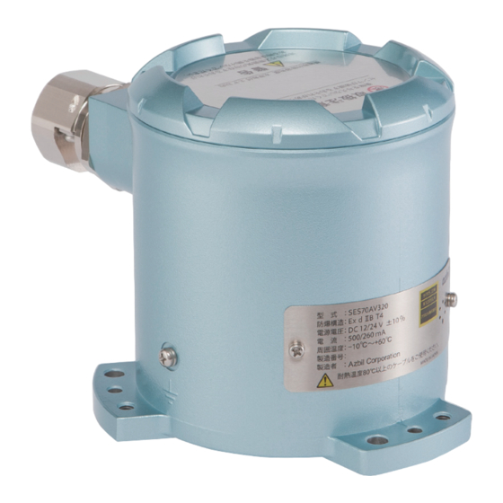
Chapter 2. NAMES AND FUNCTIONS OF PARTS „ Names of parts Adjustment hole for manufacturer Cable gland Level adjustment M6 use only (3 places) Cover Cable clamp screw hole (3 places) Lock nut Warning label φ7 device mounting hole (3 places) Battery Battery holder Screw terminal block... -
Page 18: X84; Internal Structure „
Chapter 2. NAMES AND FUNCTIONS OF PARTS „ Internal structure 111 mm 122.5 mm Explosion-proof case Waveform records RISC microcomputer real-time SI calculation Accelerometer „ Measurement principles The accelerometer uses a highly sensitive position detector to precisely detect the positional deviation of the pendulum in response to acceleration. It then sends an electrical signal (current) proportional to the positional deviation of the pendulum from the servo-amplifier to the drive circuit (drive coil+magnet) in order to return the pendulum to the reference point position. -
Page 19: Chapter 3. Installation
Chapter 3. INSTALLATION WARNING For explosion-proof instrumentation, install and wire this unit in accordance with the National Institute of Industrial Safety's User's Guidelines for Electrical Installations for Explosive Gas Atmospheres in General Industry (Tokyo, 1994 [in Japanese]). This unit is certified as a pressure-resistant explosion-proof construction (Ex d IIC T4). Install this unit in a location conforming to the conditions for a flameproof structure. - Page 20 Chapter 3. INSTALLATION When installing this unit, select one of the methods shown below, depending on the installation conditions. z If the installation surface is level within ±3° (1) Select a flat concrete surface for installation. (2) Put three anchors in the surface, aligned with the three 7 mm mounting holes in the unit.
- Page 21 Chapter 3. INSTALLATION (2) Put three anchors in the concrete surface for attaching the mounting plate. (3) Attach the mounting plate to the anchors as shown in the figure below. Sensor unit Upper nut Mounting plate Lower nut Concrete Anchor (4) Adjust the three lower nuts so that the mounting plate is level.
-
Page 23: Chapter 4. Wiring
Chapter 4. WIRING WARNING For explosion-proof instrumentation, install and wire this unit in accordance with the National Institute of Industrial Safety's "User's Guidelines for Electrical Installations for Explosive Gas Atmospheres in General Industry" (Tokyo, 1994 [in Japanese]). Use cables with a heat resistance to temperatures of 80 °C or more. If a cable with a heat resistance of less than 80 °C is used, the unit will no longer be a certified explo- sion-proof product. -
Page 24: X84; Wiring Procedure „
Chapter 4. WIRING „ Wiring Procedure (1) Loosen the setscrew to open the cover. Handling Precautions • If it is difficult to open the cover, put an appropriate tool, such as the handle of a screwdriver, in the grooves on the cover after the case has been secured, and then turn the tool in the direction indicated by the arrow to open the cover. - Page 25 Chapter 4. WIRING Note • The table below shows the proper amount of packing compression for various cable diameters. The appropriate amount of packing compression varies depending on the cable diameter and the packing inner diameter. Measure the outer diameter of the cable and choose the most appropriate amount of compression for the cable from the table below.
- Page 26 Chapter 4. WIRING z Screw terminal block Terminal No. Signal Power (+) (12/24 V DC) Power (-) (0 V DC) 3, 4 Relay contact output 1 (vibration detection output 1) 5, 6 Relay contact output 2 (vibration detection output 2) 7, 8 Relay contact output 3 (vibration detection output 3) z Spring terminal block...
- Page 27 Chapter 4. WIRING Handling Precautions • For explosion-proof instrumentation, install and wire this unit in accordance with the National Institute of Industrial Safety's User's "Guidelines for Electrical Installations for Explosive Gas Atmospheres in General Industry" (Tokyo, 1994 [in Japanese]). • Keep wiring away from cables connected to a commercial power supply or motor drive power supply that is likely to produce electrical noise.
-
Page 28: X84; Connecting The Battery „
„ Lightning surge protection When extended signal and power lines are used, if there is a risk of power surge caused by lightning, use Azbil Corporation's FA SurgeNon surge protector (QN430C series). Model No. Status Power supply... - Page 29 Chapter 4. WIRING z Connection example Shielded cable SES70 Power supply Power +24 V supply Receiver for vibration Vibration detection detection signal 1 output 1 Receiver for vibration Vibration detection detection signal 2 output 2 Vibration detection Receiver for vibration...
- Page 30 Chapter 4. WIRING Handling Precautions • Make the wiring between the SurgeNon and the unit, power supply, receiver, etc., as short as possible. • For wiring for RS-485, do not connect an external terminating resistor. If a terminating resistor is connected to either end of the transmission line, communication is not possible.
-
Page 31: Chapter 5. Preparations For Start-Up
(7) Firmly tighten the cover until its flange tightly contacts the top edge of the case. (8) Turn on the power. After approximately 60 s have elapsed, Initialization mode changes to measurement mode, and the unit is then ready for earthquake mea- surement. SLP-SE7 Smart Loader Package for SES70 Intelligent Earthquake Sensor, No. CP-UM-5756E... - Page 32 Chapter 5. PREPARATIONS FOR START-UP Note • Before putting the unit into actual operation for the first time, clear the waveforms using the loader before turning OFF the power in step (6) so that the waveforms recorded during setup work are deleted. The waveforms recorded during work can be cleared completely.
-
Page 33: Chapter 6. Internal Processing
Chapter 6. INTERNAL PROCESSING 6 - 1 Modes „ Mode transition After the earthquake sensor is turned on, it operates according to the mode transi- tions shown below. There are four modes, which change depending on the specific operation or conditions. POWER ON Initialization mode •... -
Page 34: X84; Functions Of The Modes „
Chapter 6. INTERNAL PROCESSING „ Functions of the modes The available functions vary depending on which of the four modes below is active. Initialization mode Measurement mode Standby mode Maintenance mode z Initialization mode In this mode the hardware is checked and system control information and numeri- cal processing values are initialized. - Page 35 Chapter 6. INTERNAL PROCESSING z Measurement mode The mode changes to measurement mode if no serious failures are detected and if initialization mode operations are completed correctly. In measurement mode, the various operations and judgment processes that are the basic processing of an earthquake sensor are executed.
- Page 36 Chapter 6. INTERNAL PROCESSING z Standby mode The mode changes to standby mode if any of the following occurs: • In measurement mode, a mode transition command is received via communica- tions. • In initialization mode, a system error occurs when a serious failure is detected. •...
- Page 37 Chapter 6. INTERNAL PROCESSING z Maintenance mode The mode changes to maintenance mode if a mode change command is received in measurement mode via communications or if the DI1 diagnosis input is kept ON for 2 s or longer. An operational check of the earthquake sensor input, output, and accelerometer is conducted as phases 1–3 of the maintenance sequence.
- Page 38 Chapter 6. INTERNAL PROCESSING z Status of functions in all modes Initialization mode Measurement mode Standby mode Maintenance mode Status of functions in all modes Function Initialize Measurement Standby Maintenance Initialization for internal calculation (acceleration, SI value , synthe- sized AC acceleration, JMA seismic intensity scale equivalent value ––...
-
Page 39: Internal Calculation Processes
Chapter 6. INTERNAL PROCESSING 6 - 2 Internal Calculation Processes „ Internal Calculation X-, Y-, and Z-axis acceleration signal (V) Temperature signal (V) Acceleration filter calculation for calculation Acceleration filter calculation for control X-, Y-, and Z-axis acceleration signal for calculation Temperature signal X-, Y-, and Z-axis acceleration signal for control Acceleration characterization compensation calculation... -
Page 40: X84; Various Calculations And Judgment Processes „
Chapter 6. INTERNAL PROCESSING „ Various calculations and judgment processes This section gives an overview of the calculation processes. Each calculation is executed at intervals of 10 ms. 6 - 7 Output Functions (P. 6-29) shows calculations and judgment processes. shows the resulting values. - Page 41 Chapter 6. INTERNAL PROCESSING PV bias 3-axis synthesized AC adjusted acceleration value for control noise protection PV bias 2-axis synthesized AC adjusted acceleration value for control noise protection Values that the user reads out as PV PV bias 3-axis synthesized AC adjusted acceleration value for calculation noise protection Synthesized AC acceleration (PV) PV bias...
-
Page 42: X84; Si Calculation „
The SI that is finally output is the largest of the values in the eight directions. The SI value calculated by the SES70 on the basis of the seven natural periods and vector projection in 8 directions is called SI #1. An SI value calculated on the basis of 24 natural periods and 16 directions, which is called SI #2, can also be selected. -
Page 43: X84; Synthesized Ac Acceleration Calculation „
(Sv) for a period (T) of 0.1 to 2.5 s. As shown in the figure on the left, the SES70 uses a polygon to approximate the speed response spectrum (Sv) of each of the seven natural periods in order to obtain a highly accurate SI calculation. -
Page 44: X84; Calculation Of The Jma Seismic Intensity Scale Equivalent Value „
Chapter 6. INTERNAL PROCESSING „ Calculation of the JMA seismic intensity scale equivalent value Calculation of the seismic intensity (I or JMA seismic intensity) that is equiva- lent to the measured vibration can be based on either of two correlation equations formulated by Prof. -
Page 45: Waveform Recording
Chapter 6. INTERNAL PROCESSING 6 - 3 Waveform Recording In waveform recording, the adjusted acceleration values for 3-axis calculations, the data of which is sampled at inter- vals of 10 ms, are recorded for 360 s if the conditions for recording are satisfied. Data including the date and time, SI value, synthesized AC acceleration value for calculation, and JMA seismic intensity scale equivalent value is record- ed as the header information for each waveform recording. - Page 46 Chapter 6. INTERNAL PROCESSING Handling Precautions • As shown below, the default settings for the SES70 are different from those for the older SES50/51/55/60 models. Be careful when using the unit without changing the default settings. Note: The reason for making threshold value recording the default on the SES70 is that the latest earthquake or tremors will be recorded, and for checking the stability of the installation.
-
Page 47: X84; Example Of Maximum Value Recording Without Trigger Update „
Chapter 6. INTERNAL PROCESSING „ Example of maximum value recording without trigger update In the explanatory diagram below for maximum value recording, chronological changes in acceleration and SI value are shown to illustrate the methods of accelera- tion waveform recording when an earthquake occurs. Chronological changes in waveform header information are also shown in the waveform header information table ( P. - Page 48 Chapter 6. INTERNAL PROCESSING P4 waveform data P0 waveform data Acceleration (raw) (Gal) Time (s) P4 temporary trigger point SI value = 0.2 kine 16:05:00 P0 trigger point SI value = 26 kine SI value 16:06:55 (raw) (kine) T time (s) 360s 330s = 16:04:30...
-
Page 49: X84; Example Of Maximum Value Recording With Trigger Update „
Chapter 6. INTERNAL PROCESSING „ Example of maximum value recording with trigger update In the same way as for maximum value recording without trigger update, the chronological changes in acceleration and SI value are shown to illustrate the meth- od of acceleration waveform recording when an earthquake occurs. Chronological changes in waveform header information are also shown in the waveform header information table ( P. - Page 50 Chapter 6. INTERNAL PROCESSING P4 waveform data P0 waveform data Acceleration (raw) (Gal) Time (s) P4 temporary P4 trigger point trigger point SI value = 32 kine SI value = 0.2 kine 16:05:25 16:05:00 P0 trigger point SI value = 26 kine SI value 16:10:55 (raw)
-
Page 51: X84; Example Of Threshold Value Recording „
Chapter 6. INTERNAL PROCESSING „ Example of threshold value recording In the explanatory diagram below for threshold value recording, chronological changes in acceleration and SI value are shown to illustrate the methods of accelera- tion waveform recording when an earthquake occurs. Chronological changes in waveform header information are also shown in the waveform header information table ( P. - Page 52 Chapter 6. INTERNAL PROCESSING P4 waveform data P5 waveform data Acceleration (raw) (Gal) Time (s) P5 trigger point P4 trigger point SI value = 32 kine SI value = 10 kine 16:10:30 16:05:00 Trigger threshold = 10 kine SI value (raw) (kine) 330s...
-
Page 53: X84; Forced Waveform Recording „
Chapter 6. INTERNAL PROCESSING „ Forced waveform recording Forced waveform recording operates in standby mode to record data for one wave- form. In forced waveform recording, waveform recording for 360 s is started by the recording start trigger sent from the loader. Handling Precautions •... -
Page 54: Vibration Detection And Liquefaction Judgment Functions
{(JMA seismic intensity PV) AND (liquefaction)} Handling Precautions • As shown below, the vibration detection judgment conditions of the SES70 are different from those for the older SES50/51/55/60 models. Be careful when using the unit without changing the default settings. - Page 55 Chapter 6. INTERNAL PROCESSING 1. SI value: Checks whether the earthquake is sufficient in scale to cause liquefaction. 2. Synthesized AC acceleration for calculation: Identifies the surface waveform and liquefaction waveform. 3. Estimated displacement: Checks for amplified displacement due to liquefaction. 4.
-
Page 56: Noise Protection Function
Chapter 6. INTERNAL PROCESSING 6 - 5 Noise Protection Function This unit distinguishes intrusive noise, such as electromagnetic or impact waveforms, from acceleration signals, as shown in the figure below. If noise occurs, the SI and synthesized AC acceleration values increase and the unit enters the noise protection state, in which incorrect determinations and incorrect output of the vibration detection judgment and liquefaction judg- ment are prevented. - Page 57 Chapter 6. INTERNAL PROCESSING z Zero-cross noise detection (ZCN) In this detection method, if an AC acceleration for calculation having a long period occurs, which is not normal for vibration waveforms like those of an earthquake, it is judged to be zero-cross noise. A zero-cross occurs when the AC acceleration value for calculation changes from positive to negative, or vice versa.
-
Page 58: Error Diagnosis Functions
Chapter 6. INTERNAL PROCESSING 6 - 6 Error Diagnosis Functions This unit executes various error diagnoses during operation in order to ensure high reliability. The diagnosis results can be checked using the serious failure output (DO2), minor failure output (DO1), or LED indicators on the device. -
Page 59: X84; Diagnostic Functions According To The Mode „
Chapter 6. INTERNAL PROCESSING „ Diagnostic functions according to the mode 1. Initialization mode Errors are detected, except for accelerometer errors. If any serious failure occurs, the device enters the system error state in standby mode. 2. Measurement mode Errors are detected, except for accelerometer errors. 3. - Page 60 Chapter 6. INTERNAL PROCESSING 10. Diagnosis function for acceleration noise error (noise detection) and accelera- tion noise continuous error (serious failure) The acceleration is analyzed for characteristics of non-earthquake waveforms to judge whether or not a failure has occurred. If this noise error is detected, the unit enters the noise detection state, and then the noise protection state, in which it is prevented from updat- ing control outputs such as vibration detection output, liquefaction output, and analog output.
-
Page 61: Output Functions
Chapter 6. INTERNAL PROCESSING 6 - 7 Output Functions „ Output update and hold processes After the low cutoff process and hold process are applied to the SI value, synthe- sized AC acceleration, and JMA seismic intensity scale equivalent value calculation results, and the hold process is applied to the vibration detection and liquefaction judgment results, they are reflected by the AO (4–20 mA), relay (1a), and DO4 output (transistor output (Nch open drain)). -
Page 62: X84; Manual Output „
Chapter 6. INTERNAL PROCESSING For relay output, if the ON/OFF output of DO4 is held “ON, ” and the result of the output update changes from OFF to ON, the hold begins. Hold completion Hold time re-reset Hold time reset Judgment result hold time Judgment result Judgment hold result... -
Page 63: X84; Output Adjustment (Constant Drift) „
Chapter 6. INTERNAL PROCESSING „ Output adjustment (constant drift) Constant drift of the AO output or vibration detection output can have four pos- sible causes: (1) Constant interfering vibration (2) Constant electrical or electromagnetic field noise (3) Sensor internal circuit noise (4) AO output circuit drift (0.3 % FS max.) Before adjusting the output, take corrective measures against causes (1) and (2) above, such as changing the installation location and ambient environment condi-... -
Page 64: X84; Output Selection „
„ Output selection SES70 output function or SES60-compatible output functions can be selected with the loader. The SES60-compatible output function is used to make the following revised SES70 output functions the same as those of the SES60. SES70 output function... -
Page 65: X84; Outputs According To Mode „
Chapter 6. INTERNAL PROCESSING „ Outputs according to mode The various outputs have different output result processing depending upon which of the four modes the unit is in, and the unit's operating state. For the output in each mode, the operation described in the lowest row of the "Operating state" col- umn has priority. -
Page 66: Maintenance Sequence
Chapter 6. INTERNAL PROCESSING 6 - 8 Maintenance Sequence By switching to maintenance mode using diagnosis input (DI1) or the loader, the operation of the outputs and accel- erometer can be checked. The following describes the maintenance sequence for checking output operation. „... - Page 67 Chapter 6. INTERNAL PROCESSING (14) Under these circumstances, if the DI1 input remains ON for 2 s or longer, or when a mode change request from the loader or RS-485 is received, the mode changes to initialization mode, the DO1 minor failure output enters the fast ON/OFF status, and the DO3 noise protection output is turned OFF.
-
Page 68: Led Output Functions
Chapter 6. INTERNAL PROCESSING 6 - 9 LED Output Functions Four LEDs indicate the mode and error status. In initialization mode, as shown in the table below, the LED indication automatically changes in the order shown, beginning from the top row. LED1: Minor failure LED2: Serious failure LED3: Noise protection... -
Page 69: Chapter 7. Loader Access Data
However, note that the details of this chapter may differ from the actual specifica- tions of the loader. SLP-SE7 Smart Loader Package for SES70 Intelligent Earthquake Sensor, No. CP-UM-5756E z Monitoring data The following data can be read in real time on the PC monitor: •... -
Page 70: X84; Changing Of Settings „
Chapter 7. LOADER ACCESS DATA z Detailed error data Detailed information on detected errors, such as serious failure, noise detection, and minor failure, is summarized by error level, and is reflected in the general error information. Error level Error Serious failure Minor failure Noise detection ●... - Page 71 Note: The above settings also apply to vibration detection judgments 2 and 3. * The default vibration detection judgment settings for the SES70 differ from those of SES60. Vibration detection judgment function (P. 6-22) ...
- Page 72 5.0 Gal JMA seismic intensity scale PV low cutoff 0.0 to 3.0 Note: The default settings of the SES70 are different from those of the SES60. All of the 3 settings for SES60 are 0. z AO ratio The ramp for the analog output can be adjusted.
- Page 73 Either the SES70 output function or the SES60-compatible output function can be chosen. The SES60-compatible output function is used to make the necessary changes in the SES70 output functions so that the SES70 has the same outputs as those of the SES60. Output selection (P. 6-32) Default: SES70 output function...
-
Page 74: X84; Waveform Recording „
Chapter 7. LOADER ACCESS DATA „ Waveform recording Using the loader, the recorded waveform data can be read out or deleted, and forced waveform recording can also be executed. z Readout of recorded waveform data list The header data (time stamp, SI value, synthesized AC acceleration, JMA seismic intensity scale equivalent value, and error flag, etc.) of the recorded waveform data can be read. - Page 75 (DO1), serious failure output (DO2), or noise protec- tion output (DO3), the settings will differ from the actual DO terminal status. The table below shows the relationship of the settings and the actual terminal status. SES70 terminal status Item Manual output setting...
-
Page 76: X84; Diagnosis And Adjustment Function „
Chapter 7. LOADER ACCESS DATA „ Diagnosis and adjustment function Bias adjustment and diagnosis of the accelerometer can be executed using the loader in standby mode. z Zero adjustment The bias is adjusted automatically so that the adjusted acceleration value is close to 0 Gal. -
Page 77: Chapter 8. Maintenance And Troubleshooting
Chapter 8. MAINTENANCE AND TROUBLESHOOTING WARNING If you use the Smart Loader Package (sold separately), do so in a non-hazardous area where there is no danger of explosion or fire. When there might be an explosive atmosphere, do not open the cover. When discarding the battery, do not throw it into the fire. -
Page 78: X84; Troubleshooting „
After checking the details of the current error, reset the power. readout is faulty. Recorded waveform data may be deleted. If the same error occurs again, contact the azbil Group or one of its sales representatives. A/D converter error (serious A/D converter is faulty. -
Page 79: Chapter 9. Disposal
Chapter 9. DISPOSAL When discarding this device, dispose of it properly as industrial waste, following local regulations. WARNING When discarding the battery, do not throw it into the fire. Doing so may cause it to explode. CAUTION Dispose of used batteries appropriately according to local regulations. - Page 80 Memo...
-
Page 81: Chapter 10. Specifications
Chapter 10. SPECIFICATIONS 10 - 1 Specifications Item Description Basic Explosion-proof standard Exd II BT 4 (TIIS pressure-resistant explosion-proof construction) specifications Rated acceleration range ±2000 Gal (in x, y, and z directions) Acceleration measurement ±2200 Gal (in x, y, and z directions) range Acceleration measurement 1 Gal (for DC acceleration measurement) - Page 82 User's manual, No. CP-SP-1393E Accessories (sold separately) Smart Loader Package (SLP-SE7) Replacement Replacement battery Part No.: 81446431-001 parts Manufacturer: Azbil Corporation Electrochemical: Manganese dioxide lithium battery Nominal voltage: 3 V Rated capacity: 240 mAh Maintenance parts set for Part No.: 81447670-001 SES70...
-
Page 83: Performance Specifications
Chapter 10. SPECIFICATIONS 10 - 2 Performance Specifications Item Description Synthesized AC acceleration 0 to 4000 Gal measurement range SI measurement range 0 to 300 kine Measurement range of JMA seismic 0 to 7.9 intensity scale equivalent value Analog Output type 4–20 mA current source DC output, without isolation output* D/A conversion method... -
Page 84: Other Specifications
Chapter 10. SPECIFICATIONS 10 - 3 Other Specifications „ Communication specifications Item Description Loader Connection The dedicated cable is connected to the loader jack. specifications Communication system TTL level half-duplex 3-wire system Baud rate 115200 bps Communication Communication method 3-wire RS-485, half-duplex Communication switchover When the loader cable is connected, RS-485 is capable of reading data only. -
Page 85: Appendix
APPENDIX „ Glossary Term Description Related sections Page Accelerometer The acceleration detection element that is built into this unit. NAMES AND FUNCTIONS OF PARTS P. 2-1 The accelerometer can detect acceleration on the X-, Y-, and Z-axes. Performance Specifications P. 10-3 SI value A numeric value correlated with earthquake damage. -
Page 86: X84; Method Of Determining Acceleration Accuracy App-2
APPENDIX Term Description Related sections Page Serious failure This failure may affect control output such as vibration detection Error diagnosis functions P. 6-26 output and liquefaction detection output. LED output function P. 6-36 The serious failure output turns ON and the control output turns OFF. Noise detection &... - Page 87 APPENDIX (3) Measure the X-axis FSG sensitivity. αX = αX+ – αX –980 The following accuracy standards apply to the FSG sensitivity calculated from the above expression: FSG sensitivity ±2 % FSG (1960 Gal – 39.2 Gal ≤ αX ≤ 1960Gal + 39.2 Gal) (4) Measure the X-axis FSG middle point.
- Page 88 FSG middle point ±3 % FSG (980 – 58.8 Gal ≤ αZ ≤ 980 + 58.8 Gal) FSG−mid z Example of measurement equipment (Azbil Corporation’s inspection equipment) Azbil Corporation uses static acceleration generation equipment with orthogonal- ized turntables on two axes with a horizontal plane adjustment function for accu- racy inspection.
- Page 89 APPENDIX „ Relationships between JMA seismic intensity, acceleration, SI value, and measured JMA seismic intensity Application of Previous JMA seismic intensity level New JMA seismic intensity level JMA seismic inten- JMA seismic Acceleration (Gal) JMA seismic Measured JMA seismic SI value (kine) (SI) sity scale equiva- intensity intensity...
- Page 91 Mar. 2017 6-32 Table of “ Output selection” changed. „ 10-2 Maintenance parts set for SES70 was added. 10-3, 10-4 Old page 10-2 to 10-3 End of the manual Terms and Conditions were changed (to version No. AA511A-014-09). Dec. 2018 ii, 3-1 WARNING was changed.
- Page 92 Warranty period and warranty scope 1.1 Warranty period Azbil Corporation’s products shall be warranted for one (1) year from the date of your purchase of the said products or the delivery of the said products to a place designated by you.
- Page 93 Although acceleration of the above situation varies depending on the conditions or environment of use of the products, you are required not to use any Azbil Corporation’s products for a period exceeding ten (10) years unless otherwise stated in specifications or instruction manuals.
- Page 94 Specifications are subject to change without notice. (10) 1-12-2 Kawana, Fujisawa Kanagawa 251-8522 Japan https://www.azbil.com 1st edition: Apr. 2015 (V) 3rd edition: Dec. 2018 (A)
Need help?
Do you have a question about the SES70 and is the answer not in the manual?
Questions and answers