Table of Contents
Advertisement
Quick Links
• FAST SHIPPING AND
DELIVERY
• TENS OF THOUSANDS OF
IN-STOCK ITEMS
• EQUIPMENT DEMOS
• HUNDREDS OF
MANUFACTURERS
SUPPORTED
• LEASING/MONTHLY
RENTALS
• ITAR CERTIFIED
SECURE ASSET SOLUTIONS
Artisan Technology Group
new and certified-used/pre-owned equipment
SERVICE CENTER REPAIRS
Experienced engineers and technicians on staff
at our full-service, in-house repair center
View
Instra
REMOTE INSPECTION
SM
Remotely inspect equipment before purchasing with
our interactive website at
Contact us:
(888) 88-SOURCE | sales@artisantg.com | www.artisantg.com
is your source for quality
www.instraview.com
WE BUY USED EQUIPMENT
Sell your excess, underutilized, a
We also offer credit for buy-backs
www.artisantg.com/WeBuyEqu
LOOKING FOR MORE INFORMATION?
Visit us on the web at
www.artis
information on price quotations,
specifications, manuals, and doc
Advertisement
Table of Contents

Subscribe to Our Youtube Channel
Related Manuals for NI SCXI‑1127


Summary of Contents for NI SCXI‑1127
- Page 1 Artisan Technology Group is your source for quality new and certified-used/pre-owned equipment • FAST SHIPPING AND SERVICE CENTER REPAIRS WE BUY USED EQUIPMENT DELIVERY Experienced engineers and technicians on staff Sell your excess, underutilized, a at our full-service, in-house repair center We also offer credit for buy-backs •...
- Page 2 CXI-1127 User Manual IIIWNATIONAL INSTRUMENTS'...
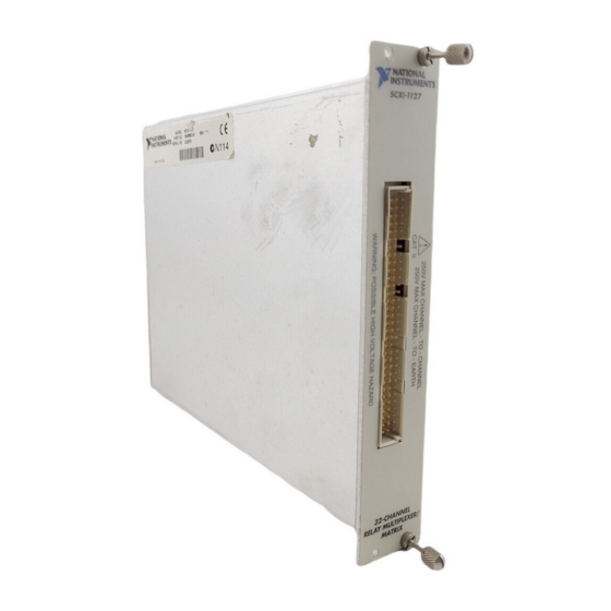
- Page 3 S O C I T m SCXI-1127 User Manual 32-Channel High-Voltage Multiplexer/Matrix Module 1 I w NATIONAL January 1999 Edition INSTRUMENTS" Part Number 322149A-01...
- Page 4 Internet Support E-mail: s u p p o r t @ n a t i n s t . com FTP Site: f tp . n a t ins t . com Web Address: h t tp : / /www n a t i n s t c o m Bulletin Board Support BBS United States: 512 794 5422 BBS United Kingdom: 01635 551422...
- Page 5 Important Information Warranty The SCXI-1127 is warranted against defects in materials and workmanship for a period o f one year from the date of shipment, as evidenced by receipts or other documentation. National Instruments will, at its option, repair or replace equipment that proves to be defective during the warranty period.
- Page 6 Compliance FCC/ D OC Radio Frequency Interference Class A Compliance This equipment generates and uses radio frequency energy and, if not installed and used in strict accordance with the instructions in this manual, may cause interference to radio and television reception. Classification requirements are the same for the Federal Communications Commission (FCC) and the Canadian Department of Communications (DOC).
- Page 7 Conventions The following conventions are used in this manual. Angle brackets containing numbers separated by an ellipsis represent a < > range of values associated with a port, bit, or signal name (for example, ACH<0..7> stands for the signals ACHO through ACH7). The »...
-
Page 8: Table Of Contents
Installing the Software Installing the Hardware Installing the SCXI-1127 Module into the SCXI Chassis Connecting the SCXI-1127 to the NI-DMM in a Single Chassis System Single 4-Slot Chassis Configuration Single 12-Slot Chassis Configuration Connecting the SCXI-1127 to the NI-DMM in a Multi-Chassis System... - Page 9 Contents Operating as a Matrix2 32x1 Matrix Configuration2 8x4 Matrix Configuration 2 Matrix Expansion2 Independent Mode2 Appendix A Specifications Appendix B Accessories Appendix C Customizing Your Module Appendix D SCXI-1127 Front Connector Appendix E Common Questions Appendix F Technical Support Resources Glossary Index Figures...
- Page 10 Figure 2-10. M i x e d Mode Scanning with an SCXI-1331 2 Figure 2-11. Hardware Scanning Flowchart2 Figure 2-12. C a b l i n g an NI-DMM and Using the TRIGO to Bus the VMC/EXT_TRIG_IN to Non-Cabled Modules2 Figure 2-13.
- Page 11 Contents Figure D-3. S C X I - 11 2 7 Front Connector Pin Assignments for Four-Wire ModeF Figure D-4. S C X I - 11 2 7 Front Connector Pin Assignments to Create an 8x4 MatrixF Tables Table 1-1. S C X I - 1 1 2 7 Configuration Table D-1.
- Page 12 Installing and Configuring the SCXI-1127 The SCXI-1127 module is a high-voltage multiplexer/matrix module. It is a high-density armature relay module that provides a 32x1, two-wire multiplexer and several switch matrix configurations on an SCXI platform. The SCXI-1127 can also operate as two 16x1 or four 8x1, two-wire multiplexers allowing a single module to handle several multiplexing needs.
-
Page 13: Installing And Configuring The Scxi-1127
ADEs have release notes containing their software installation instructions. 2. I n s t a l l the NI-SWITCH software that came on a CD with your SCXI-1127. The CD includes the software required to configure and program your SCXI-1127 module. -
Page 14: Installing The Hardware
Chapter 1 Installing and Configuring the SCXI-1127 Installing the Hardware The following section describes how to install your SCXI-1127 for use with SCXI chassis, National Instruments DAQ devices, and National Instruments DMMs. Installing the SCXI-1127 Module into the SCXI Chassis You need the following items to complete the installation: SCXI- 1127 SCXI chassis... -
Page 15: Connecting The Scxi-1127 To The Ni-Dmm In A Single Chassis System
Your SCXI-1127 modules and any other SCXI modules should already be installed in the chassis according to their installation instructions. To connect the SCXI-1127 module with an NI-DMM, follow the steps in the following section that best describes your © National Instruments Corporation... -
Page 16: Single 4-Slot Chassis Configuration
Refer to Figure 1-2 and 1-3 to make connections in the single 4-slot chassis configuration. 1 SCXI-1127 Module 4 1 -Slot HVAB-Backplane 6 NI 4060 for PCI 2 4 -Slot SCXI Chassis Adapter 7 SH9MD-9MD Cable 3 2 -Slot HVAB-Backplane... -
Page 17: Figure 1-3. 4-Slot Configuration Parts Locator Diagram
0 0 0 0 0 1 1 0 0 0 0 \ 0 0 0 1 1 0 D O M 0 0 0 . 0 0 0 0 0 0 0 O R O 5 NI 4060 for PCI 3 1 -Slot HVAB-Backplane... -
Page 18: Single 12-Slot Chassis Configuration
Refer to Figure 1-4 and 1-5 to make connections in the single 12-slot chassis configuration. 1 S C X I - 11 2 7 Module 4 1 -Slot HVAB-Backplane 6 NI 4060 for PCI 2 1 2 -Slot SCXI Chassis Adapter 7 SH9MD-9MD Cable... -
Page 19: Figure 1-5. 12-Slot Configuration Parts Locator Diagram
0 7 0 0 1 1 0 0 0 0 0 0 0 0 0 0 0 0 0 0 0 0 0 0 0 0 0 0 0 0 0 0 0 0 X 0 0 0 O H d = 0 0 0 0 0 =AO 6 NI 4060 for PCI 1 8 -Slot HVAB-Backplane Adapter 4 2-Slot HVAB-Backplane... -
Page 20: Connecting The Scxi-1127 To The Ni-Dmm In A Multi-Chassis System
Chapter 1 Installing and Configuring the SCXI-1127 Connecting the SCXI-1127 to the NI-DMM in a Multi-Chassis System The following sections describe how to configure the following multi-chassis configurations: • 4 -slot and 4-slot multi-chassis configuration • 4 -slot and 12-slot multi-chassis configuration •... -
Page 21: Figure 1-6. 4-Slot To 4-Slot Multi-Chassis Configuration Parts Locator Diagram
HV8-BAN4 Cable 2 8 -Position HVAB Plug HV8-HV8 Cable NI 4060 for PCI 10 4 -Slot SCXI Chassis Figure 1-6. 4-Slot to 4-Slot Multi-Chassis Configuration Parts Locator Diagram 1. I n s t a l l the HVAB-backplane adapters and 8-position HVAB plugs in the next chassis as described in steps 1 through 3 in Single 4-Slot Chassis Configuration. -
Page 22: 4-Slot And 12-Slot Multi-Chassis Configuration
Chapter 1 Installing and Configuring the SCXI-1127 3. Connect the SH9MD-9MD cable from the AUX OUT connector of the first chassis to the AUX IN connector of the next chassis. 4. Repeat steps 1 through 3 for each additional chassis. Note A n SC XI-1127 is required in slot 4 to establish communications with the chassis. - Page 23 0 1 1 0 0 00 0 0 0 0 M O O 0 0 0 oCEI o C E 8 1 2 -Slot SCXI Chassis 1 2 -Slot HVAB-Backplane 4 NI 4060 for PCI 9 SH9MD-9MD Cable 5 SH9MD-9MD Cable Adapter 6 8-Position HVAB Plug 10 HV8-HV8 Cable...
-
Page 24: 12-Slot And 12-Slot Multi-Chassis Configuration
Chapter 1 Installing and Configuring the SCXI-1127 1. I n s t a l l the HVAB-backplane adapters and jumper blocks in the 12-slot chassis as described in steps 1 through 3 in Single 12-Slot Chassis Configuration. 2. Connect the HV8-HV8 cable from the first chassis, normally the connector behind slot 1, to the HVAB connector (behind slot 12) of the next chassis. - Page 25 10 12-Slot SCXI Chassis Adapter 11 SH9MD-9MD Cable 6 NI 4060 for PCI Figure 1-8. 12-Slot to 12-Slot Multi-Chassis Configuration Parts Locator Diagram 1. I n s t a l l the HVAB-backplane adapters and jumper blocks in the 12-slot chassis as described in steps 1 through 3 in Single 12-Slot Chassis Configuration.
-
Page 26: Connecting The Scxi-1127 To The Ni-Dmm In A Pxi-1010 Chassis
To install your NI-DMM in slots 1 through 3 follow these steps: 1. I n s t a l l your NI-DMM in any one of slots 1 through 3. 2. I n s t a l l the 2-slot HVAB-backplane adapter behind slots 3 and 4. -
Page 27: Ni-Dmm In Pxi Slot 4 Configuration
To install your NI-DMM in slot 4 follow these steps: 1. I n s t a l l your NI-DMM in slot 4. 2. I n s t a l l the 2-slot HVAB-backplane adapter behind slots 3 and 4. - Page 28 Chapter 1 Installing and Configuring the SCXI-1127 Consult the documentation for your SCXI chassis and other SCXI modules for additional instructions and warnings. Any non-SCXI-1127 modules should already be installed according to their installation instructions. To set up the SCXI-1127 module to be accessed by a DAQ device via another SCXI module, follow these steps while referring to Figure 1-9.
-
Page 29: Connecting The Scxi-1127 To An External Dmm
Chapter 1 I n s t a l l i n g and Configuring the SCXI-1127 Figure 1-9 shows the installation of the SCXI-1127 with two DAQ devices. 6 A B 2 + 11 S C X I Chassis 1 N o n - S C X I - 11 2 7 Module 2 M I O or DIO Device 7 A B 2 - 12 Digital Signals Connector... - Page 30 Chapter 1 Installing and Configuring the SCXI-1127 • C a b l e or wires to connect the handshaking lines to the SCXI-1127 • 1 / 8 in. flathead screwdriver Consult the documentation for your SCXI chassis and other SCXI modules for additional instructions and warnings.
-
Page 31: Configuration And Self-Test
4. Y o u now have the choice of auto-detecting your modules or manually adding them depending on your application. If you are using an MIO or DIO DAQ device you can either auto-detect or manually add the modules. If you are using an NI-DMM you must manually add the modules. Auto-Detecting Modules If you selected auto-detect and the chassis is not an SCXI-2000 remote chassis, you must have your chassis connected to your DAQ device. -
Page 32: Manually Adding Modules
4. R i g h t click on the slot that is cabled to your device and select Insert. For DAQ devices this is the slot cabled to the DAQ device. For NI-DMMs this is typically slot 4, on 4-slot chassis, and slot 12 on 12-slot chassis, based on the installation instructions in earlier sections used to configure the chassis. -
Page 33: Safety Information
Chapter 1 Installing and Configuring the SCXI-1127 To remove a module or chassis, right-click on the chassis or module you want to remove and select Delete. To test the chassis configuration, right-click on the chassis and select Test. Safety Information The following cautions contain important safety information concerning hazardous voltages. - Page 34 Chapter 1 I n s t a l l i n g and Configuring the SCXI-1127 danger of introducing additional hazards, do not install unauthorized parts or modify the module. Return the module to National Instruments for service and repair to ensure that its safety features are not compromised. When using the terminal block with high common-mode voltages, you MUST insulate your signal wires appropriately.
-
Page 36: Using The Scxi-1127
Using the SCXI-1127 This chapter discusses in detail the operation of the SCXI-1127. There are two major modes of operation—operation as a multiplexer and operation as a matrix. A third mode of operation, independent mode, allows you to access advanced features of the SCXI-1127. Operating as a Multiplexer/Scanner You can configure the SCXI-1127 to operate as a multiplexer/scanner. - Page 37 Chapter 2 U s i n g the SCXI-1127 The SCXI-1331 terminal block consists of a shielded board with 84 screw terminals for easy connection to the SCXI-1127 input connector. The SCXI-1331 is shown in Figure 2-1. 1 M u l t i p l e x e r Outputs 1 -Wire Lo Reference G r o u n d Reference for 2 T w o -Wire Mode Channel Numbering ( 1 _ W I R E _ L O _ R E F )
-
Page 38: Two-Wire Channel Scanning Configuration
Chapter 2 U s i n g the SCXI-1127 mode configurations. For more information on scanning and triggering, consult the Hardware and Software Scanning section. The SCXI-1127 contains a safety interlocking mechanism that prevents high voltages from appearing on the input connector when a terminal block is not present. - Page 39 Chapter 2 U s i n g the SCXI-1127 the ABO switch to connect the multiplexer output to the high-voltage analog backplane. You can do this through NI-SWITCH. Figure 2-3 shows an example of a two-wire configuration using the SCXI-1331 terminal block. The diagram shows the two-wire terminal block connections for channels 2, 5, 24, and 27.
-
Page 40: One-Wire Channel Scanning Configuration
If you are using the module with a high-voltage backplane, you need to close the ABO switch to connect the multiplexer output to the HVAB backplane. You can do this through NI-SWITCH. Figure 2-5 shows an example of a one-wire configuration using the SCXI-1331 terminal block. -
Page 41: Four-Wire Channel Scanning Configuration
Chapter 2 U s i n g the SCXI-1127 Multiplexer Output 4 1 + OUTO± (4.) 0 0 0 0 0 0 0 0 0 0 0 0 goo000 0 0 0 0g 0 g 0 0 0 SCXI-1127 0 0 0 •... - Page 42 156- SENSE Multiplexer Figure 2-6. Four-Wire Block Diagram When used with an NI-DMM for four-wire ohms measurement, the upper differential multiplexer provides the excitation source for the four-wire channel being scanned. The EXCITATION input to the upper multiplexer is available through the OUTO+ and OUTO- screw terminals on the SCXI-1331.
- Page 43 Chapter 2 U s i n g the SCXI-1127 6A ± Excitation for Four-Wire Channel 6 6B ± Sense for Four-Wire Channel 6 XI-1331 Sense Output 1 Excitation Input — 0 0 , 0 0 0 0 0 0 0 0 0 o n o 0 0 0 0 0 0 0 0 0...
- Page 44 Artisan Technology Group is your source for quality new and certified-used/pre-owned equipment • FAST SHIPPING AND SERVICE CENTER REPAIRS WE BUY USED EQUIPMENT DELIVERY Experienced engineers and technicians on staff Sell your excess, underutilized, a at our full-service, in-house repair center We also offer credit for buy-backs •...
Need help?
Do you have a question about the SCXI‑1127 and is the answer not in the manual?
Questions and answers