Table of Contents
Advertisement
Quick Links
USER GUIDE
SCC-RLY01 Relay Module
Conventions
<>
»
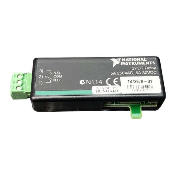
The SCC-RLY01 contains one single-pole double-throw (SPDT)
nonlatching relay capable of switching 5 A at 30 VDC when using an
SC-2345 or SC-2350, or 250 VAC when using an SCC-68. Any single
E/M Series DAQ device digital input/output (P0) line 0 to 7 can control the
SCC-RLY01.
The SCC-RLY01 uses positive logic. A digital high sets the relay, and
a digital low resets it. In the set state, the common (COM) contact is
connected to the normally open (NO) contact. In the reset state, the
common (COM) contact is connected to the normally closed (NC) contact.
The following conventions are used in this guide:
Angle brackets that contain numbers separated by an ellipsis represent
a range of values associated with a bit or signal name—for example,
P0 <3..0>.
The » symbol leads you through nested menu items and dialog box options
to a final action. The sequence File»Page Setup»Options directs you to
pull down the File menu, select the Page Setup item, and select Options
from the last dialog box.
This icon denotes a note, which alerts you to important information.
This icon denotes a caution, which advises you of precautions to take to
avoid injury, data loss, or a system crash. When this symbol is marked on
the product, refer to the Read Me First: Safety and Radio-Frequency
Interference document, shipped with the product, for precautions to take.
When symbol is marked on a product, it denotes a warning advising you to
take precautions to avoid electrical shock.
When symbol is marked on a product, it denotes a component that may be
hot. Touching this component may result in bodily injury.
Advertisement
Table of Contents

Related Manuals for NI SCC-RLY01


Summary of Contents for NI SCC-RLY01
- Page 1 E/M Series DAQ device digital input/output (P0) line 0 to 7 can control the SCC-RLY01. The SCC-RLY01 uses positive logic. A digital high sets the relay, and a digital low resets it. In the set state, the common (COM) contact is connected to the normally open (NO) contact.
-
Page 2: What You Need To Get Started
SC-2345 refers to both the SC-2345 connector block and SC-2345 with configurable connectors. SCC refers to any SCC Series signal-conditioning module. What You Need to Get Started To set up and use the SCC-RLY01, you need the following items: ❑ Hardware –... -
Page 3: Device Specific Information
Plug the SCC-RLY01 into any DIO socket J(X+9), where X is 0 to 7, on the SC-2345 or into any of the four slots that correspond to P0.0 to P0.3, on the SCC-68. -
Page 4: Specifications
390 Ω, 1/4 W P0.(X ) D GND Figure 1. SCC-RLY01 Circuit Diagram When connecting signals >60 VDC to the SCC-RLY01 module in the SCC-68, Caution you must use the high-voltage backshell. Figure 2 shows the high-voltage backshell. Figure 2. High-Voltage Backshell For information about how to configure the SCC-RLY01 module with NI-DAQmx, refer to the SCC Quick Start Guide. -
Page 5: Power Requirement
The SCC-RLY01 module is derated to 30 V maximum switching voltage in the Caution SC-2345 carrier regardless of any other voltage markings found on the SCC-RLY01 module case. Signal bandwidth........DC to 400 Hz Contact resistance ........30 mΩ max Switching time Operate time (NC to NO).... -
Page 6: Isolation Voltage
5 s dielectric withstand test Environmental Operating temperature ......0 to 50 °C Storage temperature ........–20 to 65 °C Humidity ..........10 to 90% RH, noncondensing For voltages >60 VDC, you must use the high-voltage backshell. SCC-RLY01 Relay Module User Guide ni.com... -
Page 7: Electromagnetic Compatibility
At the end of their life cycle, all products must be sent to a WEEE recycling center. For more information about WEEE recycling centers and National Instruments WEEE initiatives, visit ni.com/environment/weee.htm © National Instruments Corporation SCC-RLY01 Relay Module User Guide... - Page 8 Pin 19 5 Pin 20 Figure 4. SCC Module Bottom View Table 1 lists the signal connection corresponding to each pin. GND is the reference for the +5 V supply. Table 1. SCC-RLY01 Pin Signal Connections Pin Number Signal — —...
- Page 9 — National Instruments, NI, ni.com, and LabVIEW are trademarks of National Instruments Corporation. Refer to the Terms of Use section on ni.com/legal for more information about National Instruments trademarks. Other product and company names mentioned herein are trademarks or trade names of their respective companies.
Need help?
Do you have a question about the SCC-RLY01 and is the answer not in the manual?
Questions and answers