Advertisement
INSTALLATION GUIDE
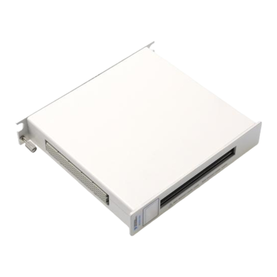
NI SCXI-1334
Terminal Block for the NI SCXI-1129
This guide describes how to install and connect signals to the National Instruments SCXI-1334
terminal block to configure the SCXI-1129 switch module as a 4 × 64 matrix.
Screw terminals on the SCXI-1334 allow you to access the 4 × 64 matrix. The SCXI-1334 also
contains terminals for scanner advanced output and external input trigger signals, two 128-pin
DIN connectors for connecting columns between modules, and 10-pin headers for connecting
rows between modules using expansion cables.
Refer to the NI Switches Getting Started Guide to determine when to install the terminal block.
Contents
Unpacking the Kit..................................................................................................................... 1
Verifying the Components........................................................................................................ 2
Connecting Signals................................................................................................................... 2
Expanding the Number of Columns..........................................................................................4
Installing the Terminal Block....................................................................................................6
Expanding the Number of Rows............................................................................................... 7
Unpacking the Kit
Caution
ground yourself using a grounding strap or by holding a grounded object, such as
your computer chassis.
1.
Touch the antistatic package to a metal part of the computer chassis.
2.
Remove the device from the package and inspect the device for loose components or any
other sign of damage.
Caution
Note
3.
Unpack any other items and documentation from the kit.
Store the device in the antistatic package when the device is not in use.
To prevent electrostatic discharge (ESD) from damaging the device,
Never touch the exposed pins of connectors.
Do not install a device if it appears damaged in any way.
Advertisement
Table of Contents

Subscribe to Our Youtube Channel
Related Manuals for NI SCXI-1334


Summary of Contents for NI SCXI-1334
- Page 1 SCXI-1129 switch module as a 4 × 64 matrix. Screw terminals on the SCXI-1334 allow you to access the 4 × 64 matrix. The SCXI-1334 also contains terminals for scanner advanced output and external input trigger signals, two 128-pin DIN connectors for connecting columns between modules, and 10-pin headers for connecting rows between modules using expansion cables.
- Page 2 Do not use this module for connection to signals or for measurements within Categories II, III, or IV. Do not connect to MAINS supply circuits (for example, wall outlets) of 115 or 230 VAC. Refer to the NI Switches Getting Started Guide for more information on measurement categories.
- Page 3 Figure 1. SCXI-1334 Top Cover Diagram NI SCXI-1334 Installation Guide | © National Instruments | 3...
- Page 4 4. Thumbscrew 8. Safety Ground Lug Expanding the Number of Columns The SCXI-1334 offers convenient methods for expanding the number of columns of a matrix using two or more SCXI-1334 terminal blocks. Caution When using matrix expansion cables, only connect terminal blocks of the same type together.
- Page 5 4×128 matrix. Related Information Installing the Terminal Block on page 6 Complete the following steps to connect the SCXI-1334 to the SCXI-1129 front panel. NI SCXI-1334 Installation Guide | © National Instruments | 5...
- Page 6 Installing the Terminal Block Complete the following steps to connect the SCXI-1334 to the SCXI-1129 front panel. Note Install the SCXI-1129 if you have not already done so. Refer to the NI Switches Getting Started Guide for more information. Plug the SCXI-1334 onto the front connector of the SCXI-1129.
- Page 7 Expanding the Number of Rows The SCXI-1334 offers convenient methods for expanding the number of rows of a matrix using two or more SCXI-1334 terminal blocks. Caution When using matrix expansion plugs, only connect terminal blocks of the same type. Connecting different types of terminal blocks can damage the module or the equipment connected to the module.
- Page 8 . You can find patents.txt ni.com/patents information about end-user license agreements (EULAs) and third-party legal notices in the readme file for your NI product. Refer to the Export Compliance Information at for the NI global trade compliance policy and how ni.com/legal/export-compliance...
Need help?
Do you have a question about the SCXI-1334 and is the answer not in the manual?
Questions and answers