Table of Contents
Advertisement
Quick Links
Advertisement
Chapters
Table of Contents

Related Manuals for BRP ROTAX 125 MAX DD2 evo


Summary of Contents for BRP ROTAX 125 MAX DD2 evo
- Page 1 Operator‘s Manual for ROTAX®-engines type 125 MAX DD2 evo Part no.: 297 733 Edition: 09/2016 BRP-Rotax GmbH & Co KG | Rotaxstrasse 1 | 4623 Gunskirchen, Austria | T: +43 7246 601 0 | F: +43 7246 6370 www.rotax.com | www.rotax-kart.com...
- Page 2 General information BRP-Rotax recommends products of the following companies: Page 1/70 Edition 09/2016...
- Page 3 Reprinting, translation or copies in whole or in part, are authorized only after written permission by BRP-Rotax GmbH & Co KG. BRP-Rotax GmbH & Co KG reserves the right at any time to discontinue or change specifications, prices, designs, features, models or equipment without incurring any obligations.
- Page 4 Introduction Congratulations on choosing the ROTAX engine Type 125 MAX DD2 evo. The ROTAX engine Type 125 MAX DD2 evo has been developed exclusively for the use in go- karts, which must only be run on specified tracks. This product has numerous technical innovations.
- Page 5 INSTALLATION INSTRUCTIONS FOR ROTAX ENGINE TYPE 125 MAX DD2 evo Page 4/70 Edition 09/2016...
-
Page 6: Table Of Contents
Table of Contents of Installation Instructions General ........................... 6 Installation and connection of the fuel system ..............7 2.1. Installation and connection of the fuel pump ..............7 Installation and connection of the carburetor ..............9 Installation of the Bowden cable for carburetor control ........... 10 Installation of the mounting plate .................. -
Page 7: General
Installation Instructions 125 MAX DD2 evo General p Warning: For the best possible engine operation, compliance with the following advice regarding installation of engine and equipment is required. p Warning: Engine operation is permitted only with equipment supplied by ROTAX. p Warning: Modifications to engine or equipment are not allowed. -
Page 8: Installation And Connection Of The Fuel System
Installation Instructions 125 MAX DD2 evo Installation and connection of the fuel system 2.1. Installation and connection of the fuel pump Æ The retaining plate, rubber buffers, fuel pump and fuel hose (with 230 mm and 1800 mm length) are already pre-assembled. See Fig. 1. Fig. - Page 9 Installation Instructions 125 MAX DD2 evo Æ The larger fuel hose (pos. 1) should be connected to the fuel filter (pos. 2) and to the fuel tank. See Fig. 4. Fig. 4 ¢ Attention: Pay attention to the arrow’s direction on the fuel filter. This must point towards the fuel pump.
-
Page 10: Installation And Connection Of The Carburetor
Installation Instructions 125 MAX DD2 evo Installation and connection of the carburetor See Fig. 5. Æ Fit the carburetor (pos. 1) into the carburetor socket and secure with a hose clamp (pos. 2) in vertical position. Æ Connect the outlet hose of the fuel pump with the fuel inlet (pos. 3) on the carburetor. -
Page 11: Installation Of The Bowden Cable For Carburetor Control
Installation Instructions 125 MAX DD2 evo Installation of the Bowden cable for carburetor control See Fig. 6. Æ Carefully remove the carburetor cover and the rubber ring (pos. 7, 8). ¢ Attention: Reset spring (pos. 6) of carb piston presses against carburetor cover and might eject carburetor cover at removal. - Page 12 Installation Instructions 125 MAX DD2 evo Æ Route the carburetor Bowden cable on the top side of the chassis tubes and attach with the cable ties supplied. Make sure that the Bowden cable does not touch any moving parts or the track. p Warning: The carburetor Bowden cable must not be kinked or restricted as the carburetor piston might get stuck in full throttle position.
-
Page 13: Installation Of The Mounting Plate
Installation Instructions 125 MAX DD2 evo Installation of the mounting plate Æ The holding bracket, the mounting plate, the solenoid valve and the ignition coil are already pre-assembled. Æ Install whole bracket kit with Allen screw M8x50 (pos. 2) and distance sleeve 8.2/12/25.5 (pos. -
Page 14: Fitting Of The Spark Plug
Installation Instructions 125 MAX DD2 evo 6. Fitting of the spark plug See Fig. 8 The engine will be supplied with a spark plug of the type NGK Iridium. Æ Remove the transport plug from the cylinder head. Æ Check electrode gap of spark plug. Adjust as required. ¿... -
Page 15: Installation And Connection Of The Rave Control Unit
Installation Instructions 125 MAX DD2 evo Installation and connection of the RAVE control unit ¿ Note: The hose package of the RAVE control is already pre-assembled. ¿ Note: The impulse restrictor is offered optionally. Insert impulse nozzle (pos. 6) about 25 mm into the 420 mm pressure line (pos. 7) using an Allen key SW4. - Page 16 Installation Instructions 125 MAX DD2 evo Fig. 11 Æ Attach the other end of the hose package (pos. 1) (short end with T-piece) to the fuel pump. Fig. 12 Æ Attach the fuel line of the hose package (pos. 1) to the impulse nipple on the engine housing.
- Page 17 Installation Instructions 125 MAX DD2 evo Fig. 14 Æ Secure both lines with a cable tie, ensuring that the black hose (pos. 2) is on top. See Fig. 15. ¢ Attention: Do not tighten cable ties too tight, because consricted lines can lead to loss of function.
-
Page 18: Check Of Oil Level In Gear Box
Installation Instructions 125 MAX DD2 evo Check oil level in gear box The gear box is already filled with the appropriate amount of oil 150 cc (0.039 gal.) by the engine manufacturer. However, before the engine is installed in the frame, the oil level must be verified or replenished. - Page 19 Installation Instructions 125 MAX DD2 evo ¿ Note: For draining the oil from the gear case, remove the magnetic oil drain plug (pos. 1) and sealing ring (pos. 2). Clean the oil drain plug before installation. Always use a new sealing ring. Fig.
-
Page 20: Installation Of Overload Clutch And Engine With Rear Axle
Installation Instructions 125 MAX DD2 evo Installation of overload clutch and engine with rear axle ¿ Note: The overload clutch is the link between the engine and the rear axle of the kart. In case that the rear axle has been blocked by (e.g. braking), the overload clutch is slipping slightl, and is not transferring the peak load from the rear axle to the engine. -
Page 21: Engine Attachment To Chassis
Installation Instructions 125 MAX DD2 evo 10. Engine attachment to chassis 10.1. Engine attachment with engine brackets See Fig. 37 and Fig. 38. The engine has to be fixed to the chassis by means of 2 engine brackets (pos. 1) (Fig. 36). Due to different distances of the 2 main rails of various chassis brands, the engine bracket is not included in the scope of supply. -
Page 22: Direct Attachment Of The Engine To Chassis
Direct attachment of the engine to chassis If the frame of the chassis is specially prepared for installation of the Rotax 125 MAX DD2 evo, then 2 sheet metal brackets with holes are welded onto the two frame tubes. The engine is clamped between the two brackets with 4 bolts. -
Page 23: Installation Of The Wiring Harness
Installation Instructions 125 MAX DD2 evo Installation of the wiring harness The wiring harness is delivered partly pre-assembled to facilitate the installation. This means that the relay, the master switch and the battery cover are already pre-assembled and wired. ¿ Note: The connector assignment is shown on the following pages. - Page 24 Installation Instructions 125 MAX DD2 evo Fig. 18 Æ Remove the isolation tape from the shift contact wire (pos. 1) and loosely fasten with a tie wrap (pos. 2) (about 130 mm from the cable lug). See Fig. 19 Fig. 19 ¿...
- Page 25 Installation Instructions 125 MAX DD2 evo Fig. 21 Æ Connect pick-up connector to pick-up sensor (pos. 1). Pay attention to the engagement of the connector. See also section 10.2 for pick-up sensor orientation options. Fig. 22 Page 24/70 Edition 09/2016...
- Page 26 Installation Instructions 125 MAX DD2 evo Æ Attach ignition cables to the wiring harness. See Fig. Fig. 1. Connector pick-up sensor 2. Connector starter 3. Connector battery 4. Connector RAVE (only applicable 125 MAX evo) 5. Connector ECU 6. Connector ignition coil 7.
-
Page 27: Installation Of The Battery And Ecu
Installation Instructions 125 MAX DD2 evo Installation of the battery and ECU 12.1. Install ECU into the battery holder Æ Prepare two rubber pads (pos. 1) and the control unit (pos. 2) for installation. Fig. 24 Æ Install the control unit into the respective rubber pad. TIP: Align at the triangular bottom of the control unit. - Page 28 Installation Instructions 125 MAX DD2 evo Fig. 26 ¢ Attention: Make sure that the connection cable (pos. 2) has been installed between the two pads (pos. 1). The connection of the ECU is on the rear side (against the driving direction).
-
Page 29: Installation Of The Battery
Installation Instructions 125 MAX DD2 evo 12.2. Installation of the battery See Fig. 27. p Warning: Make absolutely sure to avoid short-circuiting of battery terminals. A short circuit will ruin the battery and could cause an explosion. Æ Attach the battery fixture (pos. 5) with the two pipe clamps (pos. - Page 30 Installation Instructions 125 MAX DD2 evo ¿ Note: The battery terminals (pos. 1) must point in the direction of the control unit. See Fig. 29 Fig. 29 Æ Connect the positive terminal (red) of the battery. Æ Connect the negative terminal (black) of the battery. Fig.
-
Page 31: Assembly Of Paddle Shift System
Installation Instructions 125 MAX DD2 evo 13. Assembly of paddle shift system Æ Install spacer (pos. 1) into the appropriate bore (pos. 2) of the engine housing. Fig. 40 Æ Install washer (pos. 1) on one of the two Bowden cables (pos. 2). Fig. - Page 32 Installation Instructions 125 MAX DD2 evo Æ Mount Bowden cable with shift contact guidance (pos. 1) to the retaining plate (pos. Fig. 43 Æ Mount Allen screw (pos. 1), lock washer (pos. 2) and spacer (pos. 3) together with the shift contact guidance (pos. 4) onto the engine housing. Tightening torque 22 Nm.
- Page 33 Installation Instructions 125 MAX DD2 evo Æ Mount sleeve (pos. 1) onto the retaining plate (pos. 2). Fig. 46 Æ Mount second Bowden cable (pos. 1) through shift contact guidance and sleeve onto the retaining plate (pos. 2). No washer is necessary on this Bowden cable. Fig.
- Page 34 Installation Instructions 125 MAX DD2 evo Æ Thread both ends of the Bowden cables (pos. 1) through the cable support (pos. 2). Install the set screw (pos. 3) onto the cable support – just pre-assemble it, do not tighten yet. Fig.
- Page 35 Installation Instructions 125 MAX DD2 evo Æ Hand-tighten control lever left and right (pos. 1) onto the control whip (pos. 4) using M6 Allen screws (pos. 2) and washers (pos. 3). Fig. 51 ¿ Note: The control lever can also be attached to the back, depending on how it is more ergonomic for the driver.
- Page 36 Installation Instructions 125 MAX DD2 evo Æ Place the entire shifting unit onto the steering wheel and tighten it using Allen screw M6x 60 (pos. 3) and M6 lock nut (pos. 1) with washer (pos. 2). ¿ Note: Control whip must run smoothly. ¿...
-
Page 37: Installation Of The Radiator
Installation Instructions 125 MAX DD2 evo 14. Installation of the radiator See Fig. 56. Æ Mount the radiator (pos. 1) using the provided rubber buffer (pos. 5) and lock nut (pos. 8) with washer (pos. 7) on the lower support bracket on the chassis. Æ... - Page 38 Installation Instructions 125 MAX DD2 evo K00399 / Fig. 56 Æ Establish a connection between the overflow socket on the radiator filling socket and the overflow bottle with an appropriate piece of hose. ¢ Attention: To warrant the best possible engine cooling, ensure that the air stream covers the complete radiator area.
-
Page 39: Installation Of The Intake Silencer With Integrated Air Filter
Installation Instructions 125 MAX DD2 evo 15. Installation of the intake silencer with integrated air filter See Fig. 57. Æ Install the rubber intake pipe (pos. 5) in a vertical position into the bottom half (pos. 2) of the intake silencer so that the rounded intake openings point outwards. Æ... -
Page 40: Installation Of The Exhaust System
Installation Instructions 125 MAX DD2 evo 16. Installation of the exhaust system See Fig. 58. ¿ Note: On the underside of the exhaust system, two different mounting mechanisms are provided. At the front, the assembly is carried out with rubber buffers (pos. 7) between the retaining plate (pos. - Page 41 Installation Instructions 125 MAX DD2 evo K00365 / Fig. 58 Page 40/70 Edition 09/2016...
-
Page 42: Finishing Work
Installation Instructions 125 MAX DD2 evo 17. Finishing work To determine the best possible transmission ratio, the use of a rev-counter is required for observation of the speed limits. To warrant engine operation within temperature limits of the coolant, a thermo-sensor for observation of the coolant temperature is required. - Page 43 Operators Manual 125 MAX DD2 evo OPERATOR’S MANUAL FOR ROTAX ENGINE TYPE 125 MAX DD2 evo Page 42/70 Edition 09/2016...
- Page 44 Operator’s Manual 125 MAX DD2 evo Table of Contents of the Operator’s Manual Design of the ROTAX engine 125 MAX DD2 evo ............... 44 Technical description of the ROTAX engine type 125 MAX DD2 evo ......44 2.1. Type of engine ....................... 44 2.2.
-
Page 45: Design Of The Rotax Engine 125 Max Dd2 Evo
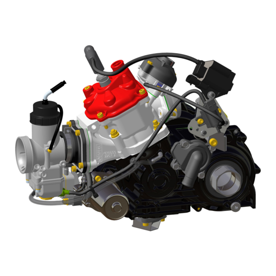
Operator’s Manual 125 MAX DD2 evo 1. Design of the ROTAX engine 125 MAX DD2 evo 2.1. Single-cylinder two-stroke engine, reed valve controlled, 125 cm displacement 2.2. Cooling circuit 2.3. Balance gear 2.4. Ignition unit 2.5. Electric starter 2.6. Electro-pneumatically controlled exhaust timing 2.7. -
Page 46: Electric Starter
Operator’s Manual 125 MAX DD2 evo 2.5. Electric starter By pressing the start button, the circuit between the battery and the electric starter will be closed by a relay. The electric starter drives the starter gear on the crankshaft via an intermediate gear with free-wheeling, until the engine starts to run. -
Page 47: Carburetor
Operator’s Manual 125 MAX DD2 evo side of the fuel pump (between fuel tank and fuel pump), a fuel filter is installed to prevent contamination of the fuel pump and carburetor. 2.12. Carburetor The carburetor (DELL’ORTO VHSB 34) is a slide-type carburetor with float system. The standard main jet is suitable for almost all operating conditions. -
Page 48: Media For Engine Operation
Operator’s Manual 125 MAX DD2 evo 3. Media for engine operation 3.1. Coolant A mixture of distilled water and aluminum-compatible antifreeze has to be used as coolant. Follow the antifreeze specifications to ensure protection against freezing up to a temperature of -20 °C / -4 °F. - Page 49 Operator’s Manual 125 MAX DD2 evo Æ Connect the battery charger to the charging connector (pos. 1). Fig. 1 Æ Connect the battery charging unit to a 110-230V, 50-60Hz power supply. During the charging procedure, the charge indicating lamp will light up red. Æ...
-
Page 50: Fuel
Operator’s Manual 125 MAX DD2 evo 3.3. Fuel For engine operation, a mixture of unleaded gasoline of at least ROZ 95 / 91 (RON+MON) / 2 min. and fully synthetic two-stroke oil, mixed at the ratio of 1:50 (2 % oil) has to be used. ¢... -
Page 51: Engine Tuning
Operator’s Manual 125 MAX DD2 evo 4. Engine tuning Performance graphs In this diagram, the different performance characteristics of the MAX engines are shown. The vertical Y-axis shows the power in kilowatts (kW). The horizontal X-axis shows the rotational speed in revolutions per minute (rpm). -
Page 52: Carburetor Calibration
45 °C / 113 °F. ¿ Note: The warranty by BRP-Rotax will no longer apply, if the carburetor calibration is carried out improperly and causes engine damage. The following application for smartphones shows the individual setting of your ROTAX 125 Max engine: The Rotax Max Jetting Guide is an app for Android™... - Page 53 Operator’s Manual 125 MAX DD2 evo 4. Now the recommended main jet value will be provided. In case a second calculation needs to be made, you can start over by simply pressing the button saying “RESET” next to the calculated value. Manual set-up: 1.
- Page 54 Operator’s Manual 125 MAX DD2 evo · In the top right corner, you can find a button called “INFO”. By clicking this button, additional information about the app as well as setting up the carburetor like float height, position of the jet needle or the air adjustment screw can be found.
- Page 55 Operator’s Manual 125 MAX DD2 evo For better understanding and as help for carburetor adjustment, the following figure describes the effect of the various adjustments, depending on the throttle position. K00264 Page 54/70 Edition 09/2016...
- Page 56 Operator’s Manual 125 MAX DD2 evo To change the carburetor main jet, proceed as follows: ¿ Note: The carburetor must not be removed from the engine in order to change the jetting. p Warning: Handle fuel in well-ventilated areas only. p Warning: When handling fuel, do not smoke or allow naked flames.
-
Page 57: Choice Of Gear Ratio
Operator’s Manual 125 MAX DD2 evo ¿ Note: In a disassembled carburetor, the position of the jet needle (pos. 3) can be changed. The standard position of the jet needle is ‘position 2’. If the clip (pos. 4) is set in ‘position 1’... - Page 58 Operator’s Manual 125 MAX DD2 evo This is a suggestion. The optimum choice can only be found with the exact knowledge of the race track. To approach and optimize the reduction gear ratio, the following charts should be helpful. The optimization procedure regarding the reduction gear ratio for a new race track is explained step-by-step in the following example: Æ...
-
Page 59: Exchange Of Gear Reduction Ratio
Operator’s Manual 125 MAX DD2 evo Gear ratio 2nd gear theoretical max. speed Traditional gear (in km/h / mile/h) ratio (at 12.500 r.p.m. and wheel Number of teeth of 2nd gear overall (in sprocket diameter 870 mm / Number of teeth of primary drive gear gear ratio sizes) -
Page 60: Operation Of The Gear Box
4.4. Operation of the gear box The ROTAX 125 MAX DD2 evo is fitted with a 2-speed gearbox that is changed manually via a shifting device. The engine also has an electronic ignition cut-off which, when changing from 1 gear, interrupts the ignition, relieving the load from the gearbox and thereby makes gear shifting easier and faster. -
Page 61: Adjustment Of Gear Shifting
Operator’s Manual 125 MAX DD2 evo Æ Due to the electronic ignition cut-off, the gas pedal can stay fully activated during the shifting operation. Shifting from 2 to 1 gear Æ Due to the high difference in rpm between the two gears, it is prohibited to shift down at a speed of over 10.200 rpm. -
Page 62: Operating Limits
Operator’s Manual 125 MAX DD2 evo 5. Operating limits min. coolant temperature 35 °C / 95 °F max. coolant temperature 85 °C / 185 °F p Warning: The engine is only allowed to be run at peak performance after reaching the specified operating temperature. -
Page 63: Stopping The Engine
Operator’s Manual 125 MAX DD2 evo Æ Press the power button once, the electric starter is activated (light turns on). Press the button again until the engine starts (Fig. 7). ¿ Note: If the engine does not start, repeat the operation after a few seconds in the same manner. -
Page 64: Running-In Procedure For The Engine
Afterwards reduce the main jet size step by step until standard size is reached. After this running-in procedure, the full power of the engine may be used. ¢ Attention: Use only fully synthetic two-stroke oil. BRP-Rotax recommends the use of XPS Kart-Tec oil. -
Page 65: Setting Of The Exhaust Valve Timing
Operator’s Manual 125 MAX DD2 evo 6.4. Setting of the exhaust valve timing The opening time of the exhaust valve is set in the ECU and depends on the engine speed. However, the ECU allows two different modes of the exhaust valve opening. These can be selected by connecting an additional cable to the cylinder head cover. - Page 66 Operator’s Manual 125 MAX DD2 evo Variant 2: Additional cable on starter relay See Fig. 10. The additional cable is NOT attached to the ground wire. The control of the exhaust valve timing is activated at 9100 rpm. ¿ Note: Isolate the additional cable with an electrical/insulating tape to the ground wire so that a possible contact with the engine ground does not affect the function.
-
Page 67: Maintenance Schedule For Engine Components
Operator’s Manual 125 MAX DD2 evo 6.5. Maintenance schedule for engine components p Warning: Non-compliance with the specified maintenance schedule could result in engine damage. FREQUENCY NOTES ENGINE Check oil level in gearbox after first 5 hours of operation, then after every 5 hours of Exchange oil in gearbox operation Clean exhaust valve and check if moving... -
Page 68: Transport Of The Kart
Operator’s Manual 125 MAX DD2 evo 7. Transport of the kart If the carburetor is still filled with fuel, the kart is only allowed to be transported in a horizontal position. If the kart is to be transported in a vertical position, the fuel must be drained from the carburetor first. - Page 69 Operator’s Manual 125 MAX DD2 evo NOTES _____________________________________________________________________________ _____________________________________________________________________________ _____________________________________________________________________________ _____________________________________________________________________________ _____________________________________________________________________________ _____________________________________________________________________________ _____________________________________________________________________________ _____________________________________________________________________________ _____________________________________________________________________________ _____________________________________________________________________________ _____________________________________________________________________________ _____________________________________________________________________________ _____________________________________________________________________________ _____________________________________________________________________________ _____________________________________________________________________________ _____________________________________________________________________________ _____________________________________________________________________________ _____________________________________________________________________________ _____________________________________________________________________________ _____________________________________________________________________________ _____________________________________________________________________________ _____________________________________________________________________________ _____________________________________________________________________________ _____________________________________________________________________________ _____________________________________________________________________________ _____________________________________________________________________________ _____________________________________________________________________________ _____________________________________________________________________________ _____________________________________________________________________________ _____________________________________________________________________________ _____________________________________________________________________________ _____________________________________________________________________________ _____________________________________________________________________________ _____________________________________________________________________________ _____________________________________________________________________________ Page 68/70...
- Page 70 Operator’s Manual 125 MAX DD2 evo _____________________________________________________________________________ _____________________________________________________________________________ _____________________________________________________________________________ _____________________________________________________________________________ _____________________________________________________________________________ _____________________________________________________________________________ _____________________________________________________________________________ _____________________________________________________________________________ _____________________________________________________________________________ _____________________________________________________________________________ _____________________________________________________________________________ _____________________________________________________________________________ _____________________________________________________________________________ _____________________________________________________________________________ _____________________________________________________________________________ _____________________________________________________________________________ _____________________________________________________________________________ _____________________________________________________________________________ _____________________________________________________________________________ _____________________________________________________________________________ _____________________________________________________________________________ _____________________________________________________________________________ _____________________________________________________________________________ _____________________________________________________________________________ _____________________________________________________________________________ _____________________________________________________________________________ _____________________________________________________________________________ _____________________________________________________________________________ _____________________________________________________________________________ _____________________________________________________________________________ _____________________________________________________________________________ _____________________________________________________________________________ _____________________________________________________________________________ _____________________________________________________________________________ _____________________________________________________________________________ _____________________________________________________________________________ Page 69/70...
- Page 71 Operator’s Manual 125 MAX DD2 evo IMPORTANT INFORMATION (SUMMARY) IMPORTANT LITER GAL. SPECIFICATION RECOMMENDED INFORMATION BRANDS Unleaded fuel of minimum octane level of FUEL 95 ROZ resp. 91 MOZ 2-STROKE OIL Fully synthetic XPS Kart-Tec During break-in: 1:33 (= 3% oil) OIL IN FUEL MIXING During normal use: 1:50 (= 2% oil) RATIO...
- Page 72 BRP-Rotax GmbH & Co KG | Rotaxstrasse 1 | 4623 Gunskirchen, Austria | T: +43 7246 601 0 | F: +43 7246 637 0 www.rotax.com | www.rotax-kart.com R and TM are trademarks of BRP-Rotax GmbH & Co KG. © 2016 BRP-Rotax GmbH & Co KG. All rights reserved.
Need help?
Do you have a question about the ROTAX 125 MAX DD2 evo and is the answer not in the manual?
Questions and answers