
Related Manuals for BRP Rotax 4-TEC 150 ECT


Summary of Contents for BRP Rotax 4-TEC 150 ECT
- Page 1 Information Center User’s Guide ROTAX 4-TEC 150, 200, 250 (ECT) ACE 60, 90 (ECT) *461153 Rev. A...
-
Page 3: Safety Information
Safety Information This user’s guide may contain the following safety messages: DANGER Indicates a hazardous situation which, if not avoided, will result in death or serious injury. WARNING Indicates a hazardous situation which, if not avoided, could result in death or serious injury. -
Page 4: Table Of Contents
TABLE OF CONTENTS SAFETY INFORMATION ....... . .1 PRODUCT DESCRIPTION ....... .3 SINGLE ENGINE INFORMATION CENTER . -
Page 5: Product Description
Product Description ® The Rotax Information Center is a cluster of information gauges, indicator lights and a digital screen to display information to the operator. Text messages can be displayed in English, French, or Spanish, and the units of measurement can be displayed in metric or imperial. The operator can view several indications such as RPM, fuel level, and en- gine temperature. -
Page 6: Single Engine Information Center
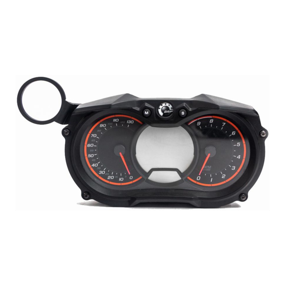
Single Engine Information Center Speedometer Fuel Level Tachometer Indicator Indicator Lights Lights 461153-01 Digital Screen Depth Sounder Indicator Hour Meter Display Numerical Display Shift Indicator iNR Multifunction Display Dual Engine Information Center Port Starboard Tachometer Fuel Level Tachometer Indicator Indicator Lights Lights 461153-02... -
Page 7: Tachometer
Tachometer The tachometer(s) provide an analog indication of the revolutions per min- ute (RPM) of the engine(s). Speedometer The speedometer provides an indication of speed in miles per hour (MPH) or kilometers per hour (km/h). On a single engine information center it is located on the left side of the ana- log gauge cluster. - Page 8 Display Area Single Dual Indicator Message Display Description Engine Engine Light information information center center Indicates engine speed Right Side Tachometer – synchronization is requested to Tachometer ECM’s Right Side Low fuel level, Tachometer LOW FUEL Tachometer approx. 25% Right Side Engine is in a low oil pressure Tachometer Low Oil Pressure...
-
Page 9: Fuel Level
Fuel Level A bar gauge located on the top of the digital screen indicates the amount of fuel. 461153-03 When the fuel tank is full, 8 segments (bars) of the indicator are turned ON. When two segments of fuel is indicated (approximately 25% fuel tank capac- ity) the low fuel indicator light will turn ON. -
Page 10: Numerical Display
Numerical Display The numerical display provides indications based on the selection made from the DISPLAY menu. The data shown is: Engine(s) Fuel Consumption - Instant Clock* Engine(s) temperature Fuel Consumption - Average* Boat speed Requires input from a GPS antenna. 461153-03 When the information center is turned ON, the numerical display defaults to the last function chosen by the operator. -
Page 11: Multifunction Display
Multifunction Display The multifunction display provides an indication of compass heading or scrolling messages. It also displays a menu for the selection of various functions which, permits changing the numerical display indication, system modes of operation, set- tings, and displaying system fault codes. 461153-03 NOTE: The compass heading selection is only available if a GPS antenna is connected to the information center. -
Page 12: Depth Sounder Indicator
Depth Sounder Indicator If the vessel is equipped with a depth sounder, the numerical display can be selected to provide an indication of the water depth. The selection of water depth is only available if a depth transducer is connected to the information center. -
Page 13: Hour Meter Display
Hour Meter Display The Hour Meter continuously displays engine time in hours (Hr). Port Engine Starboard Engine 461153-03... -
Page 14: Compass
Compass The compass heading selection is only available if a GPS antenna is con- nected to the information center. A GPS incorporated in the information center provides the indication in the multifunction display. The cardinal points, intermediate cardinal points, as well as the azimuth the boat is traveling are displayed in the multifunction display by default when the boat is moving. -
Page 15: Engine Identification
Engine Identification This indication identifies which engine is associated with the information from the numerical display. P = Port Engine S = Starboard Engine This indication will not display on a single engine information center. Engine identification displays here. 461153-03... -
Page 16: Selecting Functions
Selecting Functions When operating at speed, the multifunction display normally provides an indication of the compass direction and azimuth the boat is traveling (if the embedded GPS antenna received the proper satellite signals). To select the various functions, press the MODE button repeatedly until the desired menu is visible. -
Page 17: Changing The Clock
Changing The Clock 1. Press the MODE button repeatedly until SETTINGS is displayed. 461153-04 2. Press the SET button to validate your choice. The hour and the message CLOCK will be displayed. 461153-05 3. Press the SET button again, the message CHANGE CLOCK will be dis- played. -
Page 18: Changing Numerical Display Indication
4. Use UP / DOWN switch to adjust the clock. Only the hour indication and be changed. 5. Press MODE or SET button to save the clock setting and return to the main display. 461153-07 Changing Numerical Display Indication To change the indication in the numerical display, press the MODE button repeatedly until DISPLAY is visible in the multifunction display. -
Page 19: Main Menu
For example, to display the SPEED information: • Press the MODE button repeatedly until DISPLAY is displayed, then press SET button once • Lift up the UP and DOWN switch until SPEED is displayed • Press the SET button to confirm and save the selection Main Menu Main menu selections: ECO MODE... -
Page 20: Docking Mode
Docking Mode To activate the Docking Mode: • Reduce throttle speed to idle • Press the Mode button until Docking is displayed • Press the Set button once, the following message will be displayed: “Hold Set To Activate Or Mode To Exit” •... -
Page 21: Ski Mode
SKI Mode The SKI Mode selection is only available if a GPS antenna is connected to the information center. The SKI Mode allows the driver to adjust the launch intensity and set target speed for different rider skill levels and tow sports while maintaining a con- stant speed. -
Page 22: Cruise Mode
SKI mode selections: 461153-14 Cruise Mode Cruise mode selections: 461153-15... -
Page 23: Eco Mode
ECO Mode The iTC (Intelligent Throttle Control) system allows the operator to maintain a steady speed and constant RPM to reduce fuel consumption. To engage the fuel economy mode: 1. Press MODE button repeatedly until ECO MODE is displayed. 461153-09 2. -
Page 24: Eco Mode
ECO Mode ECO mode selections: ECO MODE ECO MODE ECO MODE ECO MODE ECO MODE ECO MODE 461153-16 Display Mode Display mode selections. 461153-17... -
Page 25: Fault Code Menu
Fault Code Menu Fault code selection is only available if faults are active in the system. Fault code selections: 461153-18 IMPORTANT: If a fault code is present for more than three consecutive driv- ing cycles, contact your dealer. NOTE: The check engine light will activate on the second consecutive driv- ing cycle when a fault is active in the engine management system. -
Page 26: Settings Menu - Engine Off
Settings Menu - Engine OFF MODE or SET MODE or SET NOTE: SYNCH is enabled by default at key ON... -
Page 27: Settings Menu - Engine Idle
Settings Menu - Engine IDLE MODE or SET MODE or SET MODE or SET... -
Page 28: Inr Functions
iNR Functions iNR OverRide With the engine OFF, the reverse gate could be activated by enabling the iNR OverRide function. In this condition, the reverse gate will be moving at 40% of the normal oper- ating speed. This function is mainly used for maintenance purposes.. The iNR OverRide can be disabled bu holding the Mode button or by start- ing the engine.
Need help?
Do you have a question about the Rotax 4-TEC 150 ECT and is the answer not in the manual?
Questions and answers