Table of Contents
Advertisement
Advertisement
Table of Contents

Related Manuals for INSTEON 2334-2 Series


Summary of Contents for INSTEON 2334-2 Series
- Page 1 Keypad Dimmer Owner’s Manual 2334-222 Page 1 of 24 Rev: 6/19/2013 10:26 AM...
-
Page 2: Table Of Contents
LEDs ..................................7 Button Taps ................................7 Button Press and Holds ............................. 8 INSTEON Setup ................................8 Add Keypad Button to a Scene as a Controller......................8 Remove Keypad Button from a Scene as a Controller ..................... 9 Adding Keypad Button To a Scene as a Responder ....................9 Removing Keypad From a Scene as a Responder .................... -
Page 3: Keypad Dimmer Dual-Band Switch
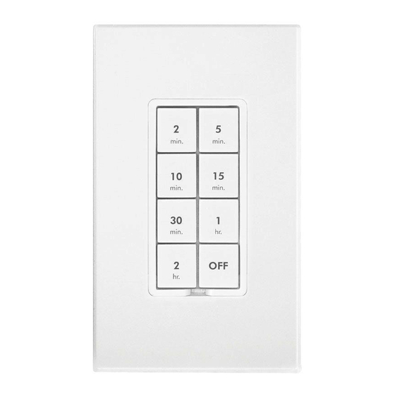
Congratulations on your purchase of the elegant, high quality Keypad Dimmer. This in-wall switch with a built-in dimmer can control up to 6 or 8 INSTEON/X10 scenes. Additionally, each button has an LED that can be easily configured as a status indicator for virtually any INSTEON device/scene you wish to monitor. Finally, it comes equipped with INSTEON’s patented dual-band communication technology for the most simple, reliable, brilliant... -
Page 4: Button Naming
If the manufacturer of the load device does not recommend dimming, use a non-dimming INSTEON on/off switch. -
Page 5: Installation - Circuit With 2 Switches
Keypad Wire Home Wire Bare copper Ground White Neutral Load Black Line With button labels right-side up, gently place Keypad into junction box and screw into place. 10) Turn breaker on. Keypad’s LEDs will illuminate. 11) Verify Keypad is working properly by turning the light on and off. 12) Reinstall the trim plate. -
Page 6: Installation - Circuit With 3 (Or More) Switches
Installation – Circuit with 3 (or more) Switches Circuits with 3 switches are called 4-way circuits, circuits with 4 are called 5-way, and so on. All switches in multi- way circuits need to be replaced by Keypads and/or SwitchLincs). 1. Turn off the circuit breaker(s) which feed power to any of the switch junction boxes (pull fuse(s)). 2. -
Page 7: Local Control
20. Turn breaker(s) on. All Keypads’ LEDs will illuminate. 21. Verify Keypad A is working properly by turning the light on and off 22. Follow steps on Page 8 to cross-link all keypads so that they all control the load. 23. -
Page 8: Button Press And Holds
INSTEON Setup A scene consists of 1 or more INSTEON devices that respond to 1 or more INSTEON controller(s). When the scene is activated (turned on), all scene members return to the states they were at when the scene was programmed. -
Page 9: Remove Keypad Button From A Scene As A Controller
6) If you wish to add more responders to the scene, repeat steps 1-5 for each additional scene responder (or see Add Multiple Responders to a Scene). If the responder is a multi-scene device such as a Keypad, tap the scene button you wish to control until its LED is in the desired scene state (on or off). Remove Keypad Button from a Scene as a Controller If you are disabling (or removing) any scene responders of Keypad, it is very important that you remove it from the Keypad scene before disabling if at all possible. -
Page 10: Advanced Features
2) Press and hold the set button until controller beeps again. Controller’s LED will continue blinking. 3) Tap the Keypad button to remove from scene. 4) Press and hold the set button on Keypad until it double-beeps. Keypad’s LED will flash once. Controller’s LED stop blinking. -
Page 11: Synchronized Scenes
Keypad’s scene button and Set button LEDs will continue blinking red. 5) For each responder you are removing: If it’s a Keypad button, tap the button. Otherwise, press and hold responder’s Set button until it beeps and/or LED flashes. 6) After all responders have been removed, Tap Keypad’s Set button. Keypad’s scene button and Set button LEDs will stop blinking. -
Page 12: Changing Button Modes (Toggle/Non-Toggle Mode)
d. Tap Switch X’s Set button. Switch X LED will beep and its LED will stop blinking. 3) Test the group by controlling the load from each switch. The load(s) and all switches will remain in synch. Changing Button Modes (Toggle/Non-Toggle Mode) You can change any button to any one of 3 button modes (we recommend using home-management software such as HouseLinc): •... -
Page 13: Turn Button Beep On Or Off
If you are no longer going to utilize an X10 address associated with Keypad, it is very important that you remove its X10 address. Otherwise, Keypad will still listen for X10 commands (somewhat hindering INSTEON reception) and may respond to spurious X10 “noise” which is unavoidable. Furthermore, Keypad will transmit an X10 address and command every time the button is pressed. -
Page 14: Factory Reset
Factory Reset Factory Reset clears all user settings from Keypad including INSTEON scenes, on-levels, ramp rates, X10 addresses, etc. With a small screwdriver or your fingernail, pull out Set button to create an air gap. Wait 10 seconds. 3) Push in Set button hold. Do not let go. -
Page 15: Led Behavior
Dimming responders will begin to brighten, unless they are already at full-on. Non-dimming responders will ignore the command and remain at their current state. When you release the button, the responders will stop going brighter. Once the scene is activated, pressing and holding the button will toggle between brightening and dimming the responders. -
Page 16: Changing To 6-Button Or 8-Button Plate
This setting is adjustable via software or a central controller only. Keypad Dimmer LED blinks red for a few seconds if one or more responders do not acknowledge a message. Changing to 6-Button or 8-Button Plate The 6-button plate provides a dedicated load ON button at the top of the switch, a dedicated load OFF button at the bottom, and four programmable secondary buttons between the On and Off buttons The 8-button plate provides a dedicated load MAIN On/Off button in the top left-most position of the keypad and seven programmable secondary buttons. -
Page 17: Additional Resources
seconds. However, when using home-management software such as HouseLinc, the ramp rate may be configured anywhere from 0.1 seconds to 8 minutes. Follow the instructions below to manually change the local ramp rate. 1) Adjust the connected light(s) to brightness corresponding to the desired Ramp-Rate Brightness Level Ramp-Rate in Seconds 90-100%... -
Page 18: Specifications
Table Top Stand Kit j/2wX/nav.aspx Specifications General 6/8-button scene Control Keypad Dimmer - INSTEON Product Name Keypad with Dimmer Dual-Band Brand INSTEON 2334-2xx Manufacturer Product Number where xx could be any number between 0 and 9. 2334-222 813922013108 Keypad Dimmer, 8 Button, White... - Page 19 Software Configurable Yes, Always RF Range 150’ Open air X10 Support X10 Addresses 256 max, unassigned by default INSTEON Device Category 0x01 Dimmable Lighting Control 6-button models: 0x42 INSTEON Device Subcategory 8-button models: 0x41 Mechanical Mounting Standard, single gang wall box...
-
Page 20: Troubleshooting
NOTE: Unless they have been unlinked, INSTEON devices that had been previously linked to Keypad Dimmer Dual-Band will still respond to button presses, even after a factory reset. The reason is that the INSTEON devices themselves have not been unlinked from Keypad Dimmer Dual-Band. See Removing Keypad Button from a Scene as a Controller. - Page 21 INSTEON signal. Keypad reception of power line Controller. Increase the X10 signal strength with an INSTEON- signal. compatible X10 booster to overcome the power line noise. My light only turns off...
- Page 22 Remove the X10 address from the button on your INSTEON Controller so it doesn't send both INSTEON and X10 commands. If the INSTEON device is still available, Unlink it When I press a button on You may have removed an from Keypad.
-
Page 23: Certification And Warranty
The repair, replacement, or refund that is provided for above shall be the full extent of Seller’s liability with respect to this product. For repair or replacement during the warranty period, call the INSTEON Gold Support Line at 800-762-7845... - Page 24 You may also have other legal rights that may vary from state to state. Protected under U.S. and foreign patents (see www.insteon.com) © Copyright 2012 INSTEON, 16542 Millikan Ave., Irvine, CA 92606, 800-762-7845, www.insteon.com Page 24 of 24...
Need help?
Do you have a question about the 2334-2 Series and is the answer not in the manual?
Questions and answers
I have the 2334-232 6 button switch all was working fine (until grandkids were playing with my buttons) now the dimmer buttons( A & B) are not working A & B controls I believe 24v recess light in the living room & dinning room the On/off controls the Dinning room Chandelier fixture need help ... what needs to be done to get things back in order. I've down loaded the manual upon falling instruction I get one beep on the A & B switch, where is the set switch: thanks for any help you recommend
To troubleshoot the INSTEON 2334-2 Series 6-button switch when dimmer buttons A and B are not working, follow these steps:
1. Check Power: Pull out the Set button to create an air gap and cut power. Then push it back in to restore power. This resets the switch.
2. Test Local Function: Press and hold the On/Off (or Main) button to adjust brightness. Tap the Set button. Then test by pressing the On/Off or Main buttons to see if they respond.
3. Verify Button Mode: Ensure buttons A and B are in the correct mode (Toggle or Non-Toggle). Button modes can be adjusted via software or a central controller.
4. Check LED Feedback: If the keypad LED blinks red, it may indicate an error. This setting is software-adjustable.
5. Use Software or Controller: Some settings, such as Beep on Button Press or Error Blink, require software or a central controller to adjust or troubleshoot.
If buttons A and B still do not respond after these steps, further software diagnostics may be required.
This answer is automatically generated