ATEN IC-485SN User Manual
Bi-directional converter
Hide thumbs
Also See for IC-485SN:
- Specifications (6 pages) ,
- User manual (20 pages) ,
- Manual (20 pages)
Table of Contents
Advertisement
Quick Links
Advertisement
Table of Contents

Subscribe to Our Youtube Channel
Related Manuals for ATEN IC-485SN


Summary of Contents for ATEN IC-485SN
- Page 2 If you encounter a problem , contact your dealer right away. SJ/T 11364-2006 The following contains information that relates to China Copyright 1998 ATEN International Co., Ltd. Manual Part No. PAPE-1134-100 Printed in Taiwan 01/1999 All brand names and trademarks are the registered property of their respective owners...
-
Page 3: Table Of Contents
Table of Contents Online Registration ..........1 Overview ............... 2 Features ............... 2 Switch Configuration ..........3 Operating Modes ............ 4 Point-to-Point ........... 4 Multidrop............5 Simplex .............8 Installation ..............9 Appendix..............10 Terminal Block Pin Assignments ......10 DCE/DTE Connection Description .....10 SW2 Pin Assignment Schematics ......10 Troubleshooting ..........11 Specifications ...........12... -
Page 4: Online Registration
You can register your product at our online support center: International - http://support.aten.com North America - http://www.aten-usa.com/ product_registration Online Support Online technical support is available to ATEN customers through our support center: International - http://support.aten.com North America - http://www.aten-usa.com/support. Troubleshooting, Documentation (including online... -
Page 5: Overview
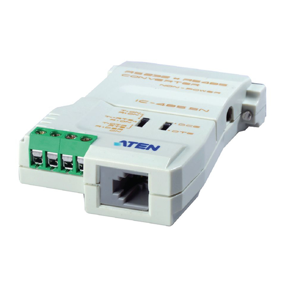
Overview The IC-485SN is a bidirectional converter for RS-232 and RS-485/RS-422 interfaces that provides Point to Point, Multidrop, and Simplex operations. A figure showing the names and locations of its features is given below: SW 1 RS-232 DB-25 Female Connecter... -
Page 6: Switch Configuration
The IC-485SN is configured by setting two slide switches. SW1 is used to select the IC- 4 8 5 S N's Device Mode; SW2 is used to select the IC-485SN's Transmitting and Receiving Mode, as shown in the table below:... -
Page 7: Operating Modes
Point-to-Point A Point-to-Point configuration is one in which two devices, located at two different places, are linked for communication by a pair of IC-485SN units. There are two configurations: Point-to-Point Full Duplex and Point-to-Point Half Duplex. 1. Point-to-Point 4 Wire Full Duplex Point-to-Point Full Duplex uses reverse four wire cabling, as shown in the figure below. -
Page 8: Multidrop
Either a two-to-one RJ-11 adapter or a combination of the terminal block and the RJ-11 jack can be used to connect the IC-485SN units to each other. One of the devices that one of the IC-485SN units connects to is assigned to be the master device. - Page 9 1. Multidrop 4 Wire Full Duplex Multidrop Full Duplex uses reverse four wire cabling to link all the connected IC-485SN units, as shown in the figure below: COM1/ COM1/ COM2 COM2 COM1/ COM2 For all IC-485SN units, set SW1 to DCE or DTE...
- Page 10 RJ-11 For all IC-485SN units, set SW1 to DCE or DTE depending on what type of device the IC-485SN will plug into (if it will plug into a DCE device, configure it for DTE, and vice versa). For all IC-485SN units, set SW2 to TxDTR/RTS, RxDSR/ON Note : Only one device at a time can talk on the bus (RTS On);during that time, the other devices must remain...
-
Page 11: Simplex
COM1/ COM2 COM1/ COM2 For all IC-485SN units, set SW1 to DCE or DTE depending on what type of device the IC-485SN will plug into (if it will plug into a DCE device, configure it for DTE, and vice versa). -
Page 12: Installation
Operation sections. 2. Plug the IC-485SN's DB-25 female connector into the PC's RS-232C port. 3. Use telephone cable to connect one IC-485SN unit to the other. a) Use four wire or two wire cable according to the information given in the Operation section. -
Page 13: Appendix
Appendix Terminal Block Pin Assignments Assignment Transmit +V Transmit -V Receive -V Receive +V DCE/DTE Connection Description Device's Connector Pin # Cable IC-485S 25/25 9/25 pin SW2 Pin Assignment Schematics TxON, RxON: 1 Tx + Tx 2 2 TX - Rx 2 3 RX - 4 RX +... - Page 14 TxRTS, RxON: 1 Tx + 2 TX - 3 RX - 4 RX + TxDTR/RTS, RxDSR/ON: 1 DATA + 2 DATA - 3 BUSY - 4 BUSY +...
-
Page 15: Troubleshooting
54 x 74.5 x 18.5 mm Dimensions (L x W x H) Troubleshooting Solution Problem Check that the IC-485SN units are securely plugged into the PC's serial ports. Check that the cables are properly Data Transmission Failure set up and properly connected. -
Page 16: Radio & Tv Interference
Radio & TV Interference Warning. This equipment generates, uses and radiates radio frequency energy and if not installed and used in accordance with the instruction manual may cause interference to radio and television reception. It has been tested and found to comply with the limits for a Class A computing device in accordance with the specifications in Subpart J of Part 15 of the FCC Rules, which are designed to provide reasonable protection against...
Need help?
Do you have a question about the IC-485SN and is the answer not in the manual?
Questions and answers