Table of Contents
Advertisement
Quick Links
User Manual
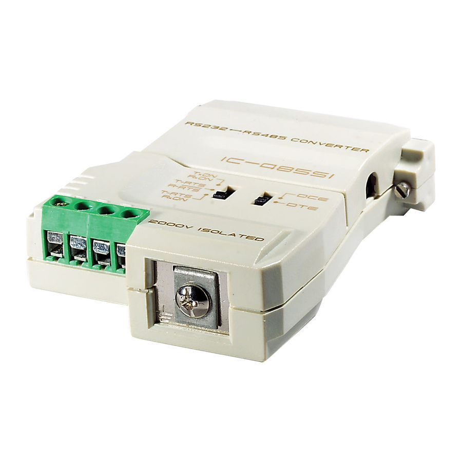
IC-485S /IC-485SI
Read this guide thoroughly and follow the installation and operation
procedures carefully in order to prevent any damage to the units and/or
any devices that connect to them.
This package contains:
M 1 IC-485S or IC-485SI Interface Converter
M 1 Power Adapter (DC 9V; 300mA)
M 1 User Manual
If anything is damaged or missing, contact your dealer.
©
®
Copyright 2005 ATEN
International Co., Ltd.
Manual Part No. PAPE-0075-201
Printed in China 01/2005
All brand names and trademarks are the registered property of their respective owners.
2005-01-04
Advertisement
Table of Contents

Related Manuals for ATEN IC-485S


Summary of Contents for ATEN IC-485S
-
Page 1: User Manual
This package contains: M 1 IC-485S or IC-485SI Interface Converter M 1 Power Adapter (DC 9V; 300mA) M 1 User Manual If anything is damaged or missing, contact your dealer. - Page 2 Warning! This equipment has been tested and found to comply with the limits for a Class A digital device, pursuant to Subpart J of Part 15 of the FCC Rules. These limits are designed to provide reasonable protection against harmful interference when the equipment is operated in a commercial environment.
- Page 3 RS-232 limitations. The IC-485S / IC-485SI is a bidirectional converter that transparently converts RS-232 signals to RS-485 signals (and vice versa). The IC-485S / IC-485SI provides Point-to-Point; Multidrop; and Simplex operations over distances of up to 1200 m (4000 ft.), thus permitting the...
-
Page 4: Switch Configuration
Switch Configuration The IC-485S / IC-485SI’s operating mode parameters are set with two slide switches: SW1 sets the Device Mode SW2 sets the Transmitting and Receiving Mode IC-485S Switch Settings SW 1 RS-232 DB-25 Female Connecter SW 2 Terminal Block... - Page 5 IC-485SI Switch Settings SW 1 RS-232 DB-25 Female Connecter SW 2 Terminal Block Power Jack Grnd. Tab Setting Position TxO, RxON TxRTS, RxRTS TxRTS, RxON - 3 - 2005-01-04...
- Page 6 Data Communications Equipment; if the IC-485S / IC-485SI is going to be plugged into a DTE device, the IC-485S / IC-485SI must be set to DCE. Data Terminating Equipment; if the IC-485S / IC-485SI is going to be plugged into a DCE device, the IC-485S / IC-485SI must be set to DTE.
-
Page 7: Operating Modes
COM port COM port For both IC-485S / IC-485SI units, set SW1 to DCE or DTE de- pending on what type of device the IC-485S / IC-485SI will plug into (if it will plug into a DCE device, configure it for DTE, and vice versa). - Page 8 COM port COM port For both IC-485S / IC-485SI units, set SW1 to DCE or DTE de- pending on what type of device the IC-485S / IC-485SI will plug into (if it will plug into a DCE device, configure it for DTE, and vice versa).
- Page 9 A Multidrop configuration is one in which more than two devices are linked for communication using several IC-485S / IC-485SI units. One of the devices that one of the IC-485S / IC-485SIs connects to is designated as the Master device. All the remaining devices that the rest of the IC-485S / IC-485SIs connect to are designated as Slave devices.
- Page 10 For all IC-485S / IC-485SI units, set SW1 to DCE or DTE depend- ing on what type of device the IC-485S / IC-485SI will plug into (if it will plug into a DCE device, configure it for DTE, and vice versa).
- Page 11 For all IC-485S / IC-485SI units, set SW1 to DCE or DTE depend- ing on what type of device the IC-485S / IC-485SI will plug into (if it will plug into a DCE device, configure it for DTE, and vice versa).
- Page 12 Monitor (IC-485S only) With Monitor Mode, the RS-485S can be wired to the lines of an RS-485 or RS-422 device to monitor the line signals. In this configuration, the RS-485S changes the functions of T+ and T- to R’+ and R’- respectively.
-
Page 13: Installation
1. Set each IC-485S / IC-485SI’s configuration switches according to the information provided in the Switch Configuration and Operating Modes sections. 2. Plug the IC-485S / IC-485SI’s DB-25 female connector into the computer’s RS-232C port. 3. Connect the IC-485S / IC-485SI units to each other:... - Page 14 (the transmitter); while terminals 3 (-V) and 4 (+V) are configured to receive data (the receiver). In Monitor mode (IC-485S only), terminals 1 and 2 are, respectively, the positive and negative of receiver 1; while terminals 3 and 4 are, respectively, the positive and negative of receiver 2.
- Page 15 DCE / DTE Connection Table Because of the polarity of the communication signals, a DTE configured device must connect to a DCE configured device. The shaded area in the figure below is an example of a DTE to DCE connection: Device's Connector Pin # Cable IC-485ASI...
-
Page 16: Troubleshooting
Data Transmission Check that the power adapter is plugged in Failure and working properly. Check that the IC-485S / IC-485SI units are securely plugged into the computers’ serial ports. Check that the cables are properly set up and properly connected.
Need help?
Do you have a question about the IC-485S and is the answer not in the manual?
Questions and answers