Table of Contents
Advertisement
Quick Links
Advertisement
Table of Contents

Subscribe to Our Youtube Channel
Related Manuals for Parker MDC Series


Summary of Contents for Parker MDC Series
- Page 1 MotorNet – DC User’s manual Rev. 0.1 August 2012 北京润诚时代科技有限公司 北京润诚时代科技有限公司 北京润诚时代科技有限公司 自动化事业部 自动化事业部 地址:北京市朝阳区汤立路218号C座968室 地址:北京市朝阳区汤立路218号C座968室 邮编:100012 邮编:100012 电话:010-84450370 电话:010-84450370 传真:010-84450371 传真:010-84450371 网址: www.runcheng.net 网址: www.runcheng.net...
- Page 2 This user manual is for the standard version of the converter. All information in this user manual, including methods, techniques and concepts described herein, are proprietary information of Parker Hannifin Manufacturing is committed to a continuous product upgrade and reserves the right to modify products and user manuals at any time without prior notice.
-
Page 3: Table Of Contents
Parker Hannifin Manufacturing Srl user’s manual MDC Index: SAFETY INSTRUCTIONS ..................... 5 Symbols and signals ....................5 General information....................5 Safety instructions for trans portation and storage ..........6 Safety instructions for commissioning..............6 Safety instructions for operation ................7 Safety instructions for maintenance ............... - Page 4 Parker Hannifin Manufacturing Srl user’s manual MDC 6.1.2.2 Object 6041h: Statusword ................40 6.1.2.3 Object 605Bh: Shutdown option code ............. 42 6.1.2.4 Object 605Ch: Disable operation option code ..........43 6.1.2.5 Object 605Ah: Quick stop option code ............44 6.1.2.6 Object 605Eh: Fault reaction option code............
-
Page 5: Safety Instructions
• Before installing and commissioning the drive, read carefully this documentation and strictly observe all technical, safety and wiring information, including identifying labels placed on the drive (ratings). In case of doubt contact the Parker Hannifin service centre. • Drives are to be intended as components for use in machine or systems. Therefore they can be used only in machine or systems that are in compliance with the low voltage directive and with the electro-magnetic compatibility directive. -
Page 6: Safety Instructions For Transportation And Storage
Parker Hannifin Manufacturing Srl user’s manual MDC 1.3 Safety instructions transportation storage • The ambient conditions given in the product documentation must be observed for transportation and storage (temperature, humidity, mechanical stress and aggressive atmosphere). • Drives contain components sensitive to electrostatic charges which can be damaged by inappropriate handling. -
Page 7: Safety Instructions For Operation
Parker Hannifin Manufacturing Srl user’s manual MDC • The user is responsible for over-current and short circuit protection of the drive. Read carefully the specification given in the user manual. 1.5 Safety instructions for operation High voltage ! Risk of electric shock ! Danger of life ! •... -
Page 8: Safety Instructions For Maintenance
Risk of personal injury. The warranty immediately decay. • In case of malfunction consult the alarm list described in the user manual or address Parker Hannifin. The drives are not field repairable. 1.7 Compatibility with RCD devices The use of RCD (Residual Current Devices) is strongly not recommended. -
Page 9: Applicable Standards
The warranty duration is 1 (one) year. The converter must not be opened, accessed or modified in any of its part. Any attempt to do so would cause the 1-year warranty to be cancelled with immediate effect. Parker Hannifin declines any responsibility for damages that may be caused by inappropriate use of the converter. -
Page 10: Introduction
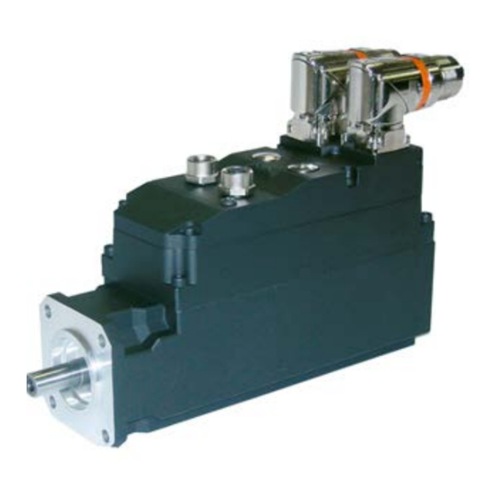
Parker Hannifin Manufacturing Srl user’s manual MDC 2 INTRODUCTION Read carefully all the sections. 2.1 Product description The MDC is a motor with electronic control integrated. Motor size from 1 Nm to 7,5 Nm of the SMB motor series (high performance brushless). -
Page 11: Identification
MDC 2.2 Identification The converters of the MDC series are available in different models. The number that follows the MDC abbreviation corresponds to the rated current of the converter in amperes. Use the following table to specify the order code:... -
Page 12: Main Hardware Features
Parker Hannifin Manufacturing Srl user’s manual MDC 3 Main hardware features 3.1 Ambient conditions operation Class 3K3, 0 … +40 °C (+32 …+104 °F) temperature storage Class 1K4, -25 … +55 °C (-4 …+131 °F) transportation Class 2K3, -25 … +70 °C (-13…+158 °F) -
Page 13: Motor Data
Parker Hannifin Manufacturing Srl user’s manual MDC 3.3 Motor data... -
Page 14: Power Supply
Parker Hannifin Manufacturing Srl user’s manual MDC 3.4 Power supply AUX VOLTAGE SUPPLY Input voltage 24 – 48VDC (0%...+10%) Max rated input current 20 * Control stage Input power Stationary brake Size Power Input power * the Max rated input current is the rated current that the aux. voltage supplies to the overall MDC chain. -
Page 15: Mounting
Parker Hannifin Manufacturing Srl user’s manual MDC 4 MOUNTING 4.1 Dimensions and weights * the connectors of I/O cables are not included Type MDC60 192+shaft MDC70 287+shaft MDC100 262+shaft... - Page 16 Parker Hannifin Manufacturing Srl user’s manual MDC...
- Page 17 Parker Hannifin Manufacturing Srl user’s manual MDC...
- Page 18 Parker Hannifin Manufacturing Srl user’s manual MDC...
-
Page 19: Mounting Instructions
Parker Hannifin Manufacturing Srl user’s manual MDC 4.2 Mounting instructions • Do not install in hazardous environments. IMPO RTANT • To ensure drive cooling, leave a free space above, below and in front of at IMPO RTANT least 100 mm. The hot air cooling must be done in an external environment, to avoid damage caused by the formation of condensation. -
Page 20: Signal Connectors
Parker Hannifin Manufacturing Srl user’s manual MDC 4.4 Signal connectors X1 – Connector male IN (motor side) X1 – IN - motor side Vdc AUX + DCBUS - DCBUS 0V AUX Ground + serv_bus - serv_bus 0V_serv_bus STO1 STO_0V STO2... - Page 21 Parker Hannifin Manufacturing Srl user’s manual MDC X3 – Connector female digital Inputs (motor side) X3 – INputs - motor side * 24V inputs * the connectors of I/O cables are not included X4 – Connector female digital Outputs (motor side) X4 –...
-
Page 22: Hybrid Cable - Connection Psi-Mdc
Parker Hannifin Manufacturing Srl user’s manual MDC 4.5 Hybrid cable – Connection PSI-MDC... -
Page 23: Leds Status
Parker Hannifin Manufacturing Srl user’s manual MDC 4.6 LEDs status No error The EtherCAT communication of the device is in working condition. Flickering Booting error Booting error was detected. INIT state reached, but parameter “Change” in the AL status register is set to 0x01: change/error. -
Page 24: Hybrid Cable: Lengths And Cross Sections
Parker Hannifin Manufacturing Srl user’s manual MDC 4.8 Hybrid Cable: lengths and cross sections Hybrid cable: Power Motor line and Signal (Ethernet Cat. 6) Max. Max. Model HYBCA – PSI Voltage Current (x2) DC bus 750VDC 20Arms Section (12AWG) (x1) -
Page 25: Layout
Parker Hannifin Manufacturing Srl user’s manual MDC 4.10 Layout EtherCAT protocol * the connectors of I/O cables are not included... - Page 26 Parker Hannifin Manufacturing Srl user’s manual MDC CANopen DSP402 protocol * the connectors of I/O cables are not included...
-
Page 27: 7 3 B D Ecimal Parameters
Parker Hannifin Manufacturing Srl user’s manual MDC D ecimal parameters 7 3 B Description field: R: read; W: write; M: memory; K: key parameter Par. Description Field Range Def. Res. Motor speed: a read-only parameter ± 15.000 1 rpm expressed in rpm; the Pr0 message is not [rpm] ever displayed on the screen. - Page 28 Parker Hannifin Manufacturing Srl user’s manual MDC Par. Description Field Range Def. Res. Pr28 Motor shaft position. Indicates the 0÷4095 absolute position of the resolver. (requires [count] b42.15=1) Pr29 Number of motor poles. 2÷64 Pr31 Operating mode (n.a.). Used to select the 202-203 active operating mode.
- Page 29 Parker Hannifin Manufacturing Srl user’s manual MDC Par. Description Field Range Def. Res. Pr71 Constant value = -1. Double word. -32768÷ +32767 Pr72 Constant value = 0. Double word. -32768÷ +32767 Pr73 Constant value = 1. Double word. -32768÷ +32767 Pr74 Constant value = 2.
-
Page 30: 4 B B Inary Parameters
Parker Hannifin Manufacturing Srl user’s manual MDC B inary parameters 7 4 B The binary parameter Pb40 can be read and set and then stored. The binary parameter Pb41 provides indications about the status of the system. The parameters Pb42 and Pb99 be read and set and then stored. - Page 31 Parker Hannifin Manufacturing Srl user’s manual MDC Par. Description Field Def. b90.1 Digital input 1. (requires b42.15=1) b90.X Status of digital input X. If X is greater than 1, this is a bit that can be stored by the user.
-
Page 32: 1 2 B V Alue Capture
Parker Hannifin Manufacturing Srl user’s manual MDC 5.1.1 V alue capture 1 1 2 B At every positive, or negative (b39.4=1), front of digital input 1, the value of Pr63:62 is captured and stored in Pr68:69 and b70.15 is set to 1 to signal the event. b70.15 is not reset automatically. -
Page 33: Can Bus Interface
Parker Hannifin Manufacturing Srl user’s manual MDC 6 CAN bus interface A CAN bus interface based on the physical layer ISO/DIS11898 is included on the converter. The Data link layer is the full CAN version 2.0 part A (ID 11 bit). -
Page 34: Dictionary Object Summary Of Ds301
Parker Hannifin Manufacturing Srl user’s manual MDC 6.1.1 Dictionary object summary of ds301 [0x1000] : device type [0x1018] : Identity object //pdo [0x1600] : PDO 1 rx mapping parameters [0x1601] : PDO 2 rx mapping parameters [0x1603] : PDO 4 rx mapping parameters... -
Page 35: Dictionary Object Summary Of Dsp402
Parker Hannifin Manufacturing Srl user’s manual MDC 6.1.2 Dictionary object summary of dsp402 [0x6007] 'Abort connection option code': with the following available values 0: No action 1: Alarm (alarm MISSING_SYNC_TRIP (Er16) if sync is missing when b271.8=1 the sync signal interval exceeds the 120% of the nominal sync cycle lasting time of index 0x1006 communication cycle period the regularity of sync signal is checked with a resolution of 2.048... - Page 36 Parker Hannifin Manufacturing Srl user’s manual MDC Following modes of operation of DSP402 are implemented beside the device control state machine: Interpolated position mode Cyclic synchronous position (only for EtherCAT) The field Error Code will contain a specific code based on the different drive alarm (see the...
- Page 37 Parker Hannifin Manufacturing Srl user’s manual MDC Device Control state machine Homing mode Device Profile 402 Motor CAN node Profile Position mode Interpolated Position mode Here by the schematic of device control with controlword e statusword Control word (6040h) State machine...
-
Page 38: Object 6040H: Controlword
Parker Hannifin Manufacturing Srl user’s manual MDC Power disable Fault Fault reaction start active Not ready to Fault switch On Switch On disabled Ready to Switch On Power enable Switched On Operation enable Quick stop active If I t current clamping is active bit 11 of the statusword rises. - Page 39 Parker Hannifin Manufacturing Srl user’s manual MDC OBJECT DESCRIPTION INDEX 6040h Name Controlword Object Code VAR Data Type UNSIGNED16 Category Mandatory ENTRY DESCRIPTION Access PDO Mapping Possible Value Range UNSIGNED16 Default Value DATA DESCRIPTION The bits of the controlword are defined as follows:...
-
Page 40: Object 6041H: Statusword
Parker Hannifin Manufacturing Srl user’s manual MDC BITS 4, 5, 6 AND 8: These bits are operation mode specific. The description is situated in the chapter of the special mode. The following table gives an overview: Operation mode Velocity mode... - Page 41 Parker Hannifin Manufacturing Srl user’s manual MDC Description M /O Ready to switch on Switched on Operation enabled Fault Voltage enabled Quick stop Switch on disabled Warning Manufacturer specific Remote Target reached Internal limit active 12 - 13 Operation mode specific 14 - 15 Manufacturer specific BITS 0 –...
-
Page 42: Object 605Bh: Shutdown Option Code
Parker Hannifin Manufacturing Srl user’s manual MDC BIT 8: This bit may be used by a drive manufacturer to implement any manufacturer specific functionality. BIT 9: REMOTE If bit 9 is set, then parameters may be modified via the CAN-network, and the drive executes the content of a command message. -
Page 43: Object 605Ch: Disable Operation Option Code
Parker Hannifin Manufacturing Srl user’s manual MDC OBJECT DESCRIPTION INDEX 605Bh Name Shutdown option code Object Code Data Type INTEGER16 Category Optional ENTRY DESCRIPTION Access PDO Mapping Value Range INTEGER16 Default Value DATA DESCRIPTION Value Description -32768 ... –1 manufacturer specific Disable drive function Slow down with slow down ramp;... -
Page 44: Object 605Ah: Quick Stop Option Code
Parker Hannifin Manufacturing Srl user’s manual MDC 6.1.2.5 Object 605A : Quick stop option code The parameter quick stop option code determines what action should be taken if the Quick Stop Function is executed. OBJECT DESCRIPTION ENTRY DESCRIPTION INDEX 605Ah... -
Page 45: Object 6060H: Modes Of Operation
Parker Hannifin Manufacturing Srl user’s manual MDC DATA DESCRIPTION Value Description -32768 ... -1 manufacturer Specific disable drive, motor is free to rotate slow down on slow down ramp slow down on quick stop ramp 6.1.2.7 Object 6060 : Modes of operation The parameter modes of operation switches the actually choosen operation mode. -
Page 46: Functional Description
Parker Hannifin Manufacturing Srl user’s manual MDC OBJECT DESCRIPTION INDEX 6061h Name Modes of operation display Object Code VAR Data Type INTEGER8 Category Mandatory ENTRY DESCRIPTION Access PDO Mapping Possible Value Range INTEGER8 Default Value DATA DESCRIPTION Same as for object 6060 modes of operation. -
Page 47: Interpolated Position Mode (Operative Mode 202)
Parker Hannifin Manufacturing Srl user’s manual MDC 6.1.4 Interpolated Position Mode (operative mode 202) In Interpolated Position Mode (Pr31=202) the cycle time is set in the object 0x1006 'communication cycle period' and depending on the value set in this object different ways of regulation are possible. -
Page 48: Object 60C0H: Interpolation Sub Mode Select
Parker Hannifin Manufacturing Srl user’s manual MDC 6.1.4.1 Object 60C0 : Interpolation sub mode select For the interpolated position mode a manufacturer may offer different interpolation algorithms. This object reflects or changes the actually chosen interpolation mode. OBJECT DESCRIPTION INDEX... - Page 49 Parker Hannifin Manufacturing Srl user’s manual MDC ENTRY DESCRIPTION Sub-Index Description number of entries 3 Entry Category Mandatory Access PDO Mapping Value Range Default Value Sub-Index Description Position setpoint in counts the first parameter of ip function fip(x1, .. xN)
- Page 50 Parker Hannifin Manufacturing Srl user’s manual MDC Operation enbled Disable Quick stop voltage shutdown Interpolation inactive Interpolation active...
-
Page 51: Mode Cyclic Synchronous Position (Operative Mode 203)
Parker Hannifin Manufacturing Srl user’s manual MDC 6.1.5 Mode Cyclic synchronous position (operative mode 203) The overall structure for this mode Cyclic synchronous position (Pr31 = 203 – only for EtherCAT protocol) is shown in Figure: Torque offset (60B2h) Velociy offset (60B1h) -
Page 52: Functional Description
Parker Hannifin Manufacturing Srl user’s manual MDC 6.1.5.1 Functional description Figure below shows the inputs and outputs of the drive control function. The input values (from the control function point of view) are the target position and optionally a position offset (to be added to the target position to allow two instances to set up the position) as well as an optional velocity offset and an optional torque offset used for feedforward control. -
Page 53: Use Of Controlword And Statusword
Parker Hannifin Manufacturing Srl user’s manual MDC 6.1.5.2 Use of controlword and statusword The cyclic synchronous position mode uses no mode specific bits of the controlword and three bits of the statusword for mode-specific purposes. Figure 64 shows the structure of the statusword. -
Page 54: Object 60B1H: Velocity Offset
Parker Hannifin Manufacturing Srl user’s manual MDC 6.1.5.3.2 Object 60B1h: Velocity offset This object shall provide the offset for the velocity value. The offset shall be given in user- defined velocity units. In cyclic synchronous position mode, this object contains the input value for velocity feed forward. -
Page 55: Drive Parameters
Parker Hannifin Manufacturing Srl user’s manual MDC 6.1.6 Drive parameters Some debug commands and parameters are added concerning CANopen Par. Description Field Range Def. Ris. Pr273 CANOPEN_CTRL_WORD. Control of drive status. -32768÷ +32767 Pr274 CANOPEN_STATUS_WORD. Status of the drive. -32768÷... -
Page 56: Revision History Of The User Manual
Parker Hannifin Manufacturing Srl user’s manual MDC 7 Revision history of the User Manual Rev 0 – 2011 First edition For other informations log into website www.sbcelettronica.com. Arranges to the manual data can be made by the manufacturer without advance notice. The data shown in the manual correspond to the specifications... - Page 57 北京润诚时代科技有限公司 北京润诚时代科技有限公司 北京润诚时代科技有限公司 自动化事业部 自动化事业部 地址:北京市朝阳区汤立路218号C座968室 地址:北京市朝阳区汤立路218号C座968室 邮编:100012 邮编:100012 电话:010-84450370 电话:010-84450370 传真:010-84450371 传真:010-84450371 网址: www.runcheng.net 网址: www.runcheng.net...
Need help?
Do you have a question about the MDC Series and is the answer not in the manual?
Questions and answers