TidalFit EP-12 Owner's Manual
Hide thumbs
Also See for EP-12:
- Owner's manual (83 pages) ,
- Electrical requirements and installation (5 pages)
Table of Contents
Advertisement
Advertisement
Table of Contents

Related Manuals for TidalFit EP-12


Summary of Contents for TidalFit EP-12
-
Page 3: Certificate Of Authenticity
U.S.A in accordance with industry quality standards. WARRANTY REGISTRATION Please activate your warranty and register your spa at www.TidalFit.com under SUPPORT, click “Owner’s”. Or mail the registration card in the back of the Owner’s Manual. Spa Serial #________________________ Spa Model:________________________... -
Page 5: Table Of Contents
Electrical Requirements and Installation..... Electrical Wiring..........GFCI Protection........... GFCI Test Trip Procedure........60 Hz GFCI Wiring Schematic (EP-16)......60 Hz Res. Wiring Schematic (EP-12/EP-14/EP-15)..50 Hz GFCI Wiring Schematic........Frequency Drive Wiring Diagrame (EP-16)....TidalFit Semi In-Ground Arch Specs (EP-12/EP-14/EP-15)............ - Page 6 Maintaining Your TidalFit..........Draining Your TidalFit..........Pillow Care............Jet Care..............Removing, Installing, and Cleaning Filters... Winterizing Your TidalFit........Replacing the Light Bulb........TidalFit Cabinet Care..........Cleaning Your TidalFit Interior....... Cover Care............Chemical Treatment of Water....... TidalFit Warranty ............Interior Spa Diagram.............
-
Page 7: Important Safety Instructions
IMPORTANT SAFETY INSTRUCTIONS IMPORTANTES CONSIGNES DE SÉCURITÉ PLEASE TAKE THE TIME TO READ ALL OF THESE WARNINGS AND CAUTIONS PRIOR TO USING YOUR SPA. PRIÈRE DE LIRE ATTENTIVEMENT TOUTES CES MISES EN GARDE AVANT D’UTILISER LE SPA. PLEASE, be a responsible spa owner. When installing and using this spa, always adhere to basic safety precautions. - Page 8 IMPORTANT SAFETY INSTRUCTIONS IMPORTANTES CONSIGNES DE SÉCURITÉ 3. For cord connected/convertible units. DANGER - Risk of Injury - a) Replace damaged cord immediately. b) Do not bury cord. c) Connect to a grounded, grounding type receptacle only. 4. DANGER - Risk of Accidental Drowning - Extreme caution must be exercised to prevent unauthorized access by children.
- Page 9 IMPORTANT SAFETY INSTRUCTIONS IMPORTANTES CONSIGNES DE SÉCURITÉ 6. DANGER - Risk of Electrical Shock - Install at least 5 feet (1.5 m) from all metal surfaces. As an alternative, a spa may be within 5 feet of metal surfaces if each metal surface is permanently connected by a mini- mum 8 AWG (8.4 mm) solid copper conductor to the wire connector on the terminal box that is provided for this purpose.
- Page 10 IMPORTANT SAFETY INSTRUCTIONS IMPORTANTES CONSIGNES DE SÉCURITÉ 6) DANGER – Risque d’électrocution – Installer à au moins 5 pieds (1,5 m) de toutes les surfaces en métal. Le spa peut également se trouver à moins de 5 pieds des surfaces en métal si chaque surface en métal est rac- cordée en permanence par un conducteur en cuivre massif d’au moins 8 AWG (8,4 mm) au raccordeur de fils du disjoncteur prévu à...
- Page 11 IMPORTANT SAFETY INSTRUCTIONS IMPORTANTES CONSIGNES DE SÉCURITÉ EQUIPMENT ASSEMBLIES An equipment assembly shall be additionally provided with the following important safety instructions 1. WARNING - Risk of Accidental Drowning. Extreme caution must be ex- ercised to prevent unauthorized access by children. to avoid accidents, ensure that children cannot use a spa or hot tub unless they are closely supervised at all times.
- Page 12 IMPORTANT SAFETY INSTRUCTIONS IMPORTANTES CONSIGNES DE SÉCURITÉ MODES D’ASSEMBLAGE Un mode d’assemblage doit également être fourni et comporter les con- signes de sécurité suivantes : 1. MISE EN GARDE – Risque de noyade accidentelle. Faire preuve d’extrême prudence afin d’empêcher l’accès non autorisé aux enfants. Pour éviter tout accident, veiller à...
- Page 13 IMPORTANT SAFETY INSTRUCTIONS IMPORTANTES CONSIGNES DE SÉCURITÉ e) Obese persons and persons with a history of heart disease, low or high blood pressure, circulatory system problems, or diabetes should consult a physician before using a spa. f) Persons using medication should consult a physician before using a spa or hot tub since some medication may induce drowsiness while other medi- cation may affect heart rate, blood pressure, and circulation.
- Page 14 IMPORTANT SAFETY INSTRUCTIONS IMPORTANTES CONSIGNES DE SÉCURITÉ Marking for equipment assemblies WARNING REDUCE THE RISK OF ELECTROCUTION Install at least 5 feet from water using nonmettalic plumbing. Do not install under spa skirt or within an enclosure that would restrict ventilation. If blower is included, install at least 1 foot above maximum water level.
- Page 15 IMPORTANT SAFETY INSTRUCTIONS IMPORTANTES CONSIGNES DE SÉCURITÉ Étiquette destinée aux modes d’assemblage MISE EN GARDE RÉDUIRE LE RISQUE D’ÉLECTROCUTION 1. Installer à 5 pieds et plus de l’eau avec de la tuyauterie non métallique. 2. Ne pas installer sous la plinthe du spa ou dans une enceinte qui limite la ventilation. 3.
- Page 16 IMPORTANT SAFETY INSTRUCTIONS IMPORTANTES CONSIGNES DE SÉCURITÉ 3. Do not operate the audio controls while inside the spa. 4. WARNING - Prevent Electrocution - Do not connect any auxiliary components (for example cable, additional speakers, headphones, ad- ditional audio/video components, etc.) to the system. 5.
- Page 17 IMPORTANT SAFETY INSTRUCTIONS IMPORTANTES CONSIGNES DE SÉCURITÉ 3. Ne pas utiliser les commandes audio lorsqu’on se trouve à l’intérieur du spa. 4. MISE EN GARDE – Prévention du risque d’électrocution – Ne pas raccorder les composantes auxiliaires (p. ex., câble, hautparleur supplé- mentaire, casque d’écoute, autres composantes audio/vidéo, etc.) au sys- tème.
-
Page 18: Electrical Requirements And Installation
Failure to do so will terminate all warranties and all listings from the independent listing facility. 1) The TidalFit requires a 240 VAC dedicated system. The pool must be hard wired to the power supply, with no plug-in connections, extension cords, or sharing of service. -
Page 19: Gfci Protection
ELECTRICAL REQUIREMENTS AND INSTALLATION GFCI PROTECTION NOTE: The GFCI section does not apply on EL systems used outside the United States. This GFCI section does not apply to GL Systems. Your pool may be equipped with a GFCI Protection feature. If your pool does not have this feature enabled, the GFCI Trip Test must occur to al- low proper pool function. -
Page 20: 60 Hz Gfci Wiring Schematic (Ep-16)
NOTE: THE POWER IN TO THIS CONTROL DOES NOT HAVE A COMMON LINE IN, ONLY A GROUND. DO NOT HOOK A COMMON TO A POWER IN TERMINAL! THIS WILL DAMAGE THE UNIT IMPORTANT: REQUIRED SIEMENS 60A GFCI CIRCUIT BREAKER TO OPERATE THE TIDALFIT EP-16... -
Page 21: 60 Hz Res. Wiring Schematic (Ep-12/Ep-14/Ep-15)
60 Hz GFCI WIRING SCHEMATIC (EP-12/14/15) 240 Volt Residential Wiring Schematic with G.F.C.I. House Breaker Box G.F.C.I. Breaker Box Spa System Box Red (Hot) 120 VAC 120 VAC Bottom View of G.F.C.I. White Green Black Hot White Green Red Hot... -
Page 22: Frequency Drive Wiring Diagrame (Ep-16)
ONLY A GROUND. DO NOT HOOK A COMMON TO A POWER IN TERMINAL! THIS WILL DAMAGE THE UNIT GREEN GROUND) CONNECT TO GROUNDING BAR WHITE (NUETRAL) BLACK GROUNDING GFCI BREAKER IMPORTANT: REQUIRED SIEMENS 60A GFCI CIRCUIT BREAKER TO OPERATE THE TIDALFIT EP-16... -
Page 23: Tidalfit Semi In-Ground Arch Specs (Ep-12/Ep-14/Ep-15)
TIDALFIT SEMI IN-GROUND EP-12/EP-14/ EP-15 ARCHITECTURAL SPECIFICATIONS SEMI Dry Weight ....2000 lbs. Filled Weight 12842 lbs....IN-GROUND Dimensions....144 in. x 91 in. x 52 in. EP-12 Volume......1300 Gallons 91.000 144.000 R10.000 88.000 CONTROL SIDE PUMP SIDE 4.500... - Page 24 TIDALFIT SEMI IN-GROUND EP-12/EP-14/ EP-15 ARCHITECTURAL SPECIFICATIONS SEMI Dry Weight ....2250 lbs. Filled Weight ....14261 lbs. IN-GROUND Dimensions....168 in. x 91 in. x 52 in. EP-14 Volume......1680 Gallons 91.000 R10.000 168.000 PUMP SIDE 88.000 CONTROL SIDE 4.000 164.885...
- Page 25 TIDALFIT SEMI IN-GROUND EP-12/EP-14/ EP-15 ARCHITECTURAL SPECIFICATIONS SEMI Dry Weight ....2400 lbs. IN-GROUND Filled Weight ....19080 lbs. Dimensions....180 in. x 91 in. x 60 in. EP-15 Volume......2000 Gallons 180.000 91.000 R.10.000 176.000 CONTROL SIDE 88.000 PUMP SIDE 4.500...
-
Page 26: Tidalfit Semi In-Ground Instructions
TIDALFIT SEMI IN-GROUND INSTRUCTIONS The depth of the dig will vary based upon the on the terrain or slope. Crane the spa into position like a normal spa delivery. - Page 27 TIDALFIT SEMI IN-GROUND INSTRUCTIONS Place 1 bag in each corner and 1 in the middle of each long side. This will allow you to remove the straps on the spa is in position. Allow the ice to melt and then the spa will be ready for back fill with gravel 3.5 in.
-
Page 28: Tidalfit Start Up
In preparation for installing your new TidalFit, you should ensure that your chosen location meets some minimum guidelines: 1) Place your TidalFit on a surface that is large enough for the entire Tidal- Fit to fit. Consider the space needed to easily access equipment compart- ments and circuit breakers. -
Page 29: Inspection
TIDALFIT START-UP INSPECTION You will want to inspect your TidalFit, prior to filling it up with water. Look for and remove any debris in the pool tub and in the filter. Verify that pump plugs are installed on the pumps and the pump unions are tight. -
Page 30: Verifying Water Circulation
I f the GFCI breaker fails to operate as described, there is a possibility of an electrical shock if the TidalFit is used. Shut off the power at the main electrical service panel until the source of the problem has been identified and corrected by a licensed electrician or qualified pool technician. -
Page 31: Priming The Pump
TIDALFIT START-UP PRIMING THE PUMP 1) Turn off power at electrical service panel. 2) Locate and loosen one of the pump plugs on each pump by turning it counterclockwise one half of one turn. 3) Allow air to escape from fittings. When a steady stream of water flows from the pump plug, close it by turning it clockwise until tight. -
Page 32: Topside Control Instructions (Ep-15)
TOPSIDE CONTROL INSTRUCTIONS (EP-15) THE MAIN SCREEN Temperature Range Water Temperature I mportant information about spa Desired Temperature Pump and Heat operation can be seen quickly Status from the Main Screen. The actual water temperature can be seen in large test and the desired water temperature is shown in smaller text. - Page 33 Jets 2 button, pump will automati- cally timeout after 15 minutes. Jets 3 Button: (If your TidalFit is equipped with a third pump.) The jets 3 button will operate pump number 3. First press of the Jets 3 button will activate pump 3.
- Page 34 TOPSIDE CONTROL INSTRUCTIONS Press the Select Button when the Shortcut option is highlighted. Shortcuts The main screen will change to shortcut operation screen. The shortcut menu assigns the operation to the navigation buttons. Ready in Rest Mode Heating Up Button: The UP button will operate pump 1. First press of the UP button will activate pump 1.
-
Page 35: Temperature Operation
TOPSIDE CONTROL INSTRUCTIONS Down Button: The Down button will operate pump 3 (if applicable). First press of the Down button will activate pump 3. A second press of the Down button will deactivate pump 3. If pump 3 is not manually turned off by pressing the Down button it will automatically timeout after 15 minutes. -
Page 36: The Settings Screen
TOPSIDE CONTROL INSTRUCTIONS High Range: Set point can be set between 80°F and 104°F Low Range: Set Point can be set between 50°F and 99°F THE SETTINGS SCREEN The Settings Screen is where all programming and other spa behaviors are controlled. This screen is where all programming and other spa behav- iors are controlled. -
Page 37: Temp Range
TOPSIDE CONTROL INSTRUCTIONS TEMP RANGE The first setting available to change is Temp Range. This system incorpo- rates two temperature range settings. The specific range that is selected (High or Low) will be displayed in the upper right hand corner of the main screen. -
Page 38: Ready Mode
TOPSIDE CONTROL INSTRUCTIONS READY MODE In ready mode the heater will maintain the set temperature. If your Tidal- Fit spa is not programmed for 24 hours Filter it will turn on the circulation pump every half an hour to test the water temperature. If the water temper- ature is one degree below the set point the circulation pump will continue to run to bring the water temperature to the set point temperature. -
Page 39: Time Of Day
TOPSIDE CONTROL INSTRUCTIONS TIME OF DAY When the time of day is highlighted. Right Button: Press the Right button to go to the Time of Day Menu. Time of Day 12:00 PM 12 HR The screen will change to Time of Day Settings. -
Page 40: Setting Filter Cycle
TOPSIDE CONTROL INSTRUCTIONS Down Button: To change the time format. Left Button: Press the left button to high light. Save Icon (you will need to press it three times to high light the save button.) Save Select Button: Press the select Icon to save and return to the main Menu. - Page 41 TOPSIDE CONTROL INSTRUCTIONS Right Button: Press the Right button to highlight Filter Cycle 1 Start time Hour. Up Button: To Increase the Filter Cycle 1 Start time hours. Down Button: To decrease the Filter Cycle 1 Start time hours. (NOTE: To change AM and PM you will need to cycle the hours past 12) Right Button: Press the Right button to high light Filter Cycle 1 Start time minutes.
- Page 42 TOPSIDE CONTROL INSTRUCTIONS Up Button: To Filter Cycle 2 on or off. Down Button: To Filter Cycle 2 on or off. Right Button: Press the Right button to high light Filter Cycle 1 Start time Hour. Up Button: To Increase the Filter Cycle 2 Start time hours. (NOTE: To change AM and PM you will need to cycle the hours past 12) Down Button: To decrease the Filter Cycle 2 Start time hours.
-
Page 43: Invert Display
TOPSIDE CONTROL INSTRUCTIONS Down Button: To decrease the Run Time Minutes. The panel calculates the end time and displays it automatically. In order to maintain sanitary conditions, as well as protect against freezing, the system will purge water from their respective plumbing by briefly running the pumps at the beginning of each filter cycle. -
Page 44: Restricting Operations (Lock)
TOPSIDE CONTROL INSTRUCTIONS Inverted: Display will be towards the outside of the spa. Settings Temp Range High Heat Mode Ready Time of Day Filter Cycles Light Cycle Invert Panel Inverted Lock When the display is inverted, the navigation buttons will also be inverted to work with the display. - Page 45 TOPSIDE CONTROL INSTRUCTIONS Down Button: Press the down button until Panel is highlighted. Select Button: Press the Select button to turn Panel lock on. The screen will change and go back to the main display. High Range Set 104 Unlock 8:32 PM Ozone Filter 1...
-
Page 46: Hold
TOPSIDE CONTROL INSTRUCTIONS HOLD Hold mode is used to disable the pump during service functions, clean- ing or replacing the filters. The hold will last for 1 hour unless the mode is exited manually. Select button: Press the select button to go back to activate the hold mode. -
Page 47: Preference
TOPSIDE CONTROL INSTRUCTIONS PREFERENCE The screen will change to the Preferences Menu. Preferences Temp Display Time Display 12HR Reminders Cleanup 0.5 HR Dolphin Color Blue Language English TIME DISPLAY R ight button: Press the right button to highlight temp Display. Select button: Press the select button to change from F°... -
Page 48: Dolphin (Not Used)
TOPSIDE CONTROL INSTRUCTIONS DOLPHIN (NOT USED) Down Button: Press the Down Button until Dolphin is highlighted. This option is not available. COLOR Down Button: Press the Down Button until Color is Highlighted. Select Button: Press the select button to change the background color on the display. -
Page 49: Heater Related Messages
TOPSIDE CONTROL INSTRUCTIONS HEATER-RELATED MESSAGES During the warmer month it is recommended to change the filter cycle duration to keep the spa from overheating with the high ambient tempera- ture. The water flow is low – M016 There may not be enough water flow through the heater to carry the heat away from the heating elements. -
Page 50: Sensor Related/Misc. Messages
TOPSIDE CONTROL INSTRUCTIONS SENSOR-RELATED/MISC. MESSAGES Flow-Related Checks Check for low water level, suction flow restriction (filters) closed valve or trapped air. The heater is too hot* – M030 One of the water temperature has detected 118°F (47.8°C) in the heater and the spa is shut down. -
Page 51: System Related Messages
TOPSIDE CONTROL INSTRUCTIONS SYSTEM RELATED MESSAGES Program memory failure – M022 Call you dealer for service. The settings have been reset– M021 Call you dealer for service if this message appears on more than one power-up. The clock has failed –M020 Call you dealer for service. - Page 52 TOPSIDE CONTROL INSTRUCTIONS REMINDER MESSAGES Check the pH May appear on a regular schedule, i.e. every 7 days. Check pH with a test kit and adjust pH with the appropriate chemicals. Check the sanitizer May appear on a regular schedule, i.e. every 7 days. Check sanitizer level and other water chemistry with a test kit and adjust with the appropriate chemicals.
-
Page 53: Swimspeed Control Instructions (Ep-16)
SWIMSPEED CONTROL INSTRUCTIONS (EP-16) 1. Adjust Up or Down as needed for preference 2. Turn Power On MAINTENANCE Perform maintenance every 9-12 months. 1. Disconnect power 2. Take panel away 3. Drain water down to benches (Top level) 4. Visually check Hydro hoses for cracks in connections and for leaks. -
Page 54: Diagnostic Messages
DIAGNOSTIC MESSAGES No message on display. Power has been cut off to the spa. • The control panel will be disabled until power re- turns. Time of day will be preserved for 30 days with a battery back-up on EL8000 and EL 5000 systems. EL1000 and some EL2000 systems reset the time of day on each power-up. - Page 55 DIAGNOSTIC MESSAGES Sensors are out of balance. If this is alternating with the temperature, it may just be a temporary condition. If the display shows only this message (periodically blinking), the pool is shut down. • If the problem persists, contact your dealer or service organization.
- Page 56 DIAGNOSTIC MESSAGES Temperature unknown. • After the pump has been running for 1 minute, the temperature will be displayed. Temperature not current in Economy or Sleep mode. • In Economy or Sleep mode, the pump may be off for hours outside a filter. If you wish to see the current pool temperature, either switch to Standard mode or turn Jets1 on for at least a minute.
- Page 57 DIAGNOSTIC MESSAGES H ardware failure. • Contact your dealer or service organization if message appears on more than one power up. Firmware install problem. • Contact your dealer or service organization if message appears on more than one power up. Configuration error.
-
Page 58: Periodic Reminder Messages
PERIODIC REMINDER MESSAGES Every 7 days. • Test and adjust pH chemical levels per manu- facturer’s instructions. Every 7 days. • Test and adust sanitizer chemical levels per manufacturer’s instructions. Every 30 days • Remove, clean, and reinstall filter per manu- facturer’s instructions. -
Page 59: Various Exercises
ROWING EXERCISE Install Rowers Press the quick release button. Snap the back of the rowing bar into the mount. Install First Set of Tension Cords Use the mounting loops as a slip knots around each safety bar. Clip tension cord to mounting loop. Clip tension cord to rowing bar. -
Page 60: Upper Body Workouts
UPPER BODY WORKOUTS Install Tension Cords Choose a desired pair of the varying length tension cords. Clip the tension cords to the mounted loops. Attach handles to the tension cords. Chest Press Standing up- right and facing away from the cords, Position your hands and elbows at your... - Page 61 TREADMILL WITH SUPER SWIM Install Super Swim Pole Attach the two poles together by matching up the brass attachments and twisting until tightened. Place bottom of the pole into the attachment on the lip of the pool, above the rowing seat. Adjust nylon rope to desired length.
-
Page 62: Maintaining Your Tidalfit
MAINTAINING YOUR TIDALFIT DRAINING YOUR TIDALFIT Your spa needs to be drained, cleaned, waxed and refilled about every six months. More frequent water changes may be necessary if bather load is heavy. A hose bib has been provided to assist you in draining your spa. -
Page 63: Jet Care
MAINTAINING YOUR TIDALFIT JET CARE W e recommend that you clean your jets when you drain your pool. However, if you do need to clean your jets in between this can be accomplished with a full pool. 1) To remove the jet inserts turn the jet counterclockwise to the off position until it stops. -
Page 64: Removing, Installing And Cleaning Filters
MAINTAINING YOUR TIDALFIT REMOVING, INSTALLING AND CLEANING FILTERS These are the steps needed to successfully replace your filters You should replace your disposable pool filters and clean your non-disposable filters every four months. 1) Turn off all power to your pool and remove the filter lid by lifting it out towards you. -
Page 65: Replacing The Light Bulb
You may wish to clean the cabinet with mild soap and water from time to time. If you elected to purchase your TidalFit with a wood cabinet, this cabinet is stained and sealed with an oil based acrylic stain. The stain is formulated especially for pool cabinet and deck applications and is resistant to ultraviolet light damage caused by sun rays. -
Page 66: Cleaning Your Tidalfit Interior
Use only the stain recommended by your dealer for refinishing your pool. CLEANING YOUR TIDALFIT INTERIOR It is important to clean the interior of your pool every time it is drained to help preserve the sheen of your pool’s surface. However, it is important that you do not use any abrasive cleaners or strong chemicals. - Page 67 Refer to the section titled “Draining your TidalFit” for instructions (page 44). WARNING: Pool damage due to improper chemicals is not cov- ered under warranty.
-
Page 68: Tidalfit Warranty
PLEASE READ THE WARRANTY THOROUGHLY. Please take a moment to register your warranty. You can register on line at http://www.tidalfit.com, click on owner login or you mail in the warranty registration card attached to this manual. For warranty outside USA and Canada, please refer to your countries Artesian Distributor. - Page 69 TIDALFIT WARRANTY COMMERCIAL APPLICATIONS ARE EXCLUDED FROM THIS AND ALL WARRANTIES. The spa must be set on a level solid surface that is sufficient to support the entire length and width of the spa. Standard building practices must be followed. Damage caused by failure to have a leveled and supported foundation under the spa is not covered under warranty.
- Page 70 TIDALFIT WARRANTY Damage caused by acts of nature, poor water chemistry, and/or improp- er maintenance will not be covered under this warranty. Alterations or replacements of components installed in the spa that are not purchased and/or approved by the MANUFACTURER, including incorrect wiring,...
- Page 71 TIDALFIT WARRANTY S TEREO AND STEREO COMPONENTS The stereo and stereo components, including speakers, sub-woofer, stereo power supply, wire harness and remote control are covered for 30 days from the original start date of the warranty. The warranty period starts either the day of delivery to the customer or eighteen (18) month from the date of manufacturing, whichever date comes first.
- Page 72 TIDALFIT WARRANTY PERFORMANCE In the event of any defect covered by this LIMITED warranty, a May Manufacturing LLC, authorized agent will correct such defect within the terms and conditions contained herein. There will be no charge for parts or labor within the above terms. However, travel charges that occur will not be covered under terms and conditions by the warranty.
- Page 73 TIDALFIT WARRANTY LEGAL REMEDIES This LIMITED WARRANTY gives specific rights, and other rights that may apply and will vary from state to state. WHAT IS NOT COVERED UNDER YOUR WARRANTY The following is a general overview of non-warranty items and work.
-
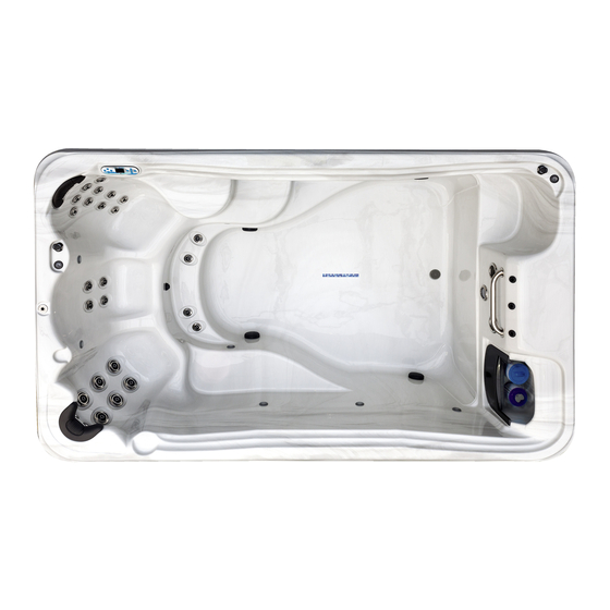
Page 74: Interior Spa Diagram
INTERIOR SPA DIAGRAM TidalFit Dual Swim Spa Configuration TidalFit Hydrotherapy Spa Configuration... - Page 75 INTERIOR SPA DIAGRAM TidalFit Quad Swim Spa Configuration TidalFit In-Ground Spa Configuration...
Need help?
Do you have a question about the EP-12 and is the answer not in the manual?
Questions and answers
Heater is dry code 27