Bogen & V250 Installation And Use Manual
Bogen use manual power vector amplifiers v35, v60, v100, v150, & v250
Hide thumbs
Also See for & V250:
- Installation and use manual (16 pages) ,
- Information (13 pages) ,
- Specifications (8 pages)

Related Manuals for Bogen & V250


Summary of Contents for Bogen & V250
- Page 1 Power Vector Amplifiers V35, V60, V100, V150, & V250 Models Installation and Use Manual © 2004 Bogen Communications, Inc. All rights reserved. Specifications subject to change without notice. 54-2072-01B 0401...
- Page 2 Every effort was made to ensure that the information in this guide was complete and accurate at the time of printing. However, information is subject to change. Important Safety Information WARNING: To Reduce The Risk of Fire Or Electric Shock, Do Not Expose This Apparatus To Rain Or Moisture.
-
Page 3: Table Of Contents
Contents PANEL DESCRIPTIONS...2-3 Power Vector Front Panel...2 Power Vector Rear Panel ...3 INSTALLATION ...4 Package Contents ...4 Ventilation and Mounting ...4 Models V250 and V150 ...4 Models V100,V60, and V35 ...4 Rack Mounting ...4 Shelf/Table Mounting ...4 Module Installation ...4 MODULES ...5 Output Modules ...5 Functionality ...5... -
Page 4: Panel Descriptions
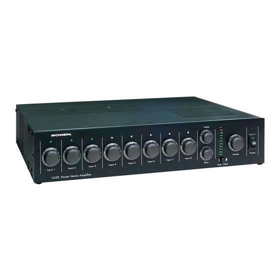
Panel Descriptions Power Vector Front Panel 1. Input Volume Control Each of the 8 inputs is controlled by an independent volume control. 2. Signal / Clip Indicator A single two-color LED located above each channel’s volume control indicates the audio activity of that channel’s input. -
Page 5: Panel Descriptions
Power Vector Rear Panel 1. AC Receptacle A grounded, unswitched AC convenience receptacle with a 500W maximum capacity is provided for external equipment. 2. AC Line Cord and Circuit Breaker A grounded, 3-wire AC line cord provides power to the amplifier and is protected by a resettable circuit breaker. -
Page 6: Installation
Module Installation Eight module bays are available to accept Bogen’s new advanced input modules. Module bays 7 & 8 can also accommodate Bogen’s new advanced output modules, thereby allowing users to customize the amplifier to suit the needs of the installation. (The bays will not accept Bogen’s older style plug-in modules.) Before installing a module, read the instructions included with the module and make the desired jumper setting changes. -
Page 7: Modules
Priorities The Power Vector series of amplifiers allows inputs to be prioritized at four different levels. The Bogen input modules contain circuitry that can cause their outputs to be muted in response to higher priority control signals from other input modules. -
Page 8: Connections
Connections Speakers Transformer-Coupled Speaker Connections Transformer-coupled, constant voltage speaker loads are connected to their respective load type (i.e., 70V speakers to the 70V terminal, 25V speakers to the 25V terminals) and the COM terminal. Make sure the selector switch is in the TRANS OUT position. A separate 8-ohm terminal is provided to drive 8-ohm (low-impedance) speakers through an output transformer tap. -
Page 9: Com And Gnd Terminals
Master Volume control. The impedance of the shorting connections must be less than 100 ohms in order to operate the control. The Bogen Remote Volume Control Panel (Model RVCP) provides a simple and elegant means of remote control. -
Page 10: Mute Control
Mute Control Each priority bus (High, Medium, and Low) can be externally activated. This allows priority buses of two or more Power Vector units to be linked together for system expansion purposes. A particular mute priority can be externally forced by shorting that priority’s bus terminal to the C terminal of the Mute Control (the C terminal is the system ground). -
Page 11: Operation
Operation Front Panel Controls & Indicators Input Volume Controls Each input module may be individually controlled by its corresponding volume control knob. Signal / Clip Indicator A single LED located above each channel’s volume control indicates the audio activity of that channel’s input. Green indicates signal present at the input. -
Page 12: Operation
Rear Panel Controls Load Selector Switch A large slide switch above the amplifier’s output barrier strip determines transformer-coupled or direct output operation. The setting of this switch controls which amplifier output terminals are active and what type of filter shape will be used for the bass control. See the connections section for more information about the load selector switch. -
Page 13: Block Diagram
Block Diagram... -
Page 14: Specifications
Power Output (RMS): V35: 35W V60: 60W V100: 100W (140W Typical, @ 1 kHz/0.1%/4Ω) V150: 150W (200W Typical, @ 1 kHz/0.1%/4Ω) V250: 250W (340W Typical, @ 1 kHz/0.1%/4Ω) Frequency Response Transformer: 45-20 kHz; 0/-2 dB @ FRP Direct: 20-20 kHz; 0/-1 dB @ FRP Distortion Transformer: 0.5% THD+N, Maximum, Full-rated bandwidth @ FRP... -
Page 15: Troubleshooting
Troubleshooting PROBLEM CONDITION Power Indicator LED is off. Power Indicator LED is red. Input Signal / Clip LED is off. NO SOUND Power Indicator LED is red. Input Signal / Clip LED is green. LED Output Meter is off. Power Indicator LED is red. Input Signal / Clip LED is green. -
Page 16: Warranty
In no event shall Bogen be liable for special, incidental or consequential dam- ages (including, but not limited to, loss of profits, loss of data or loss of use damages) arising out of the manufacture, sale or sup- plying of products, even if Bogen has been advised of the possibility of such damages or losses.
Need help?
Do you have a question about the & V250 and is the answer not in the manual?
Questions and answers