Roland NOVA-MOD SH-101 Manual
Hide thumbs
Also See for NOVA-MOD SH-101:
- Owner's manual (63 pages) ,
- Service notes (11 pages) ,
- Service manual (11 pages)
Advertisement
Quick Links
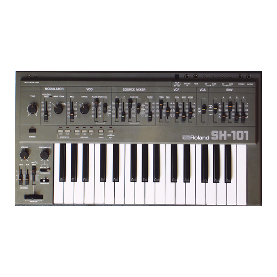
<<<NOVA-MOD>>>
LFO CLK
VCF CV
IN
IN
MODULATOR
LFO/CLK
RATE
TUNE
WAVEFORM
NORM LO HI
NOVA
SEQUENCER
POWER
VOLUME
PORTAMENTO
PORTAMENTO
TRANSPOSE
BENDER
Features:
- VCF FM:
Amazing new sounds are now added through this feature. Six FM sources are available.
- LFO Clock Input:
Syncing the Arpeggiator and LFO to external drum modules and sequencers is now possible.
As well, interesting feedback loops can be created.
- PW Modulation Source Selection:
Now you can choose a pulse width source. It is independent from the LFO's waveform setting.
OSC sources are included.
- Pulse width to near 0%:
Pulse width effects are now made more extreme and powerful.
- External Audio Input:
The ability to do FM of the VCF by an external audio source or to simply route a signal into the
audio path is now provided. Don't forget feedback loops!!
- VCF CV Input
Just plug in a foot pedal or a CV from a midi converter and your SH-101 will sing!
- LFO Rate Scalar
Ever hear a bell sound out of a 101? Try this on Hi!! Want a really slow sweep...you got it too!
- 1/4" CV/Gate In/Out Jacks
Aren't we all tired of those miniphono plugs? They should only exist on walkmans.
FM
Filter
EXT AUDIO
IN
VCO
SOURCE MIXER
MOD
PULSEWIDTH
RANGE
LFO
MAN
ENV
ARPEGGIO
LEGATO REST
PW SOURCE
DC IN
EXT CLK
IN
VCF
SUB OSC
NOISE
FREQ RES
ENV MOD KEYBD
-1
-2
-2
ROLAND
EXT AUDIO
FM SOURCE
AMOUNT
CV
GATE
CV
GATE
PHONES OUTPUT
HOLD
IN
OUT
VCA
ENVELOPE
S
R
A
D
GATE
ENV
Trig
LFO
GATE
SH-101
Advertisement

Related Manuals for Roland NOVA-MOD SH-101


Summary of Contents for Roland NOVA-MOD SH-101
- Page 1 RATE PULSEWIDTH SUB OSC NOISE FREQ RES ENV MOD KEYBD TUNE WAVEFORM RANGE GATE Trig GATE NORM LO HI SH-101 NOVA ROLAND SEQUENCER ARPEGGIO LEGATO REST POWER PW SOURCE EXT AUDIO FM SOURCE AMOUNT VOLUME PORTAMENTO PORTAMENTO TRANSPOSE BENDER Features: - VCF FM: Amazing new sounds are now added through this feature.
- Page 2 NOVA-MOD Details: Pulse width to near 0% By closing the pulsewidth to a spike, new sounds can be attained by the SH-101. This “spike” wave source is very useful for brightening a bass patch. (A bass patch, with only the sub Osc waveform assigned, can be brightened, but not raised in pitch, by adding a little pulsewidth signal with a manual setting of less than 1% duty cycle.) In another application, in which only full ramp waveform is assigned, manually raising and lowering the spike...
- Page 3 6 position Rotary Switches (Radio Shack units work fine but 3” long shafts must be cut. As well, pins must flattened to prevent interference with keyboard action, shims may be required to lower keyboard.) Roland 4 position switches (pn 13119303 SRM1034-K15) may be used also but the switches must be...
- Page 4 Roland pots (pn 13219274 EVH-5XAP20A15) may be used. The same clearance considerations must be made with respect to the key action however these pots will accept the correct Roland knobs. DPDT Switched 1/4” jack. 1/4” Jacks with shorting contact 1/4”...
- Page 5 Tools: solder iron, de-solder tool, knife, modellers saw, drill press, wire strippers and cutters. 1. Remove all knobs.(rotary and linear) 2. Remove back panel. (two of these black screws have a fine thread, note their position) 3. Remove screws to Synth Board and Bender Board. 4.
-
Page 6: Calibration Procedure
Calibration Procedure This calibration is very easy to do. All that you need is a digital voltmeter capable of reading DC with an accuracy of 1mV. It is highly recommended to connect the voltmeter to a 1/8” plug. (best done by sacrificing a cable with 1/8”... - Page 7 good ears, you may be able to adjust VR-6 without an instrument. (use keys G3 and G4 if you use a guitar tuner that reads only EADGBE notes) Note :you may have to adjust VR-7 slightly to retune. Unfortunately VR-6 adjusts the width AND the overall tuning.
- Page 8 Drill Locations PW Source / Ext. audio / FM Source/ Ext. LFO/ Ext VCF CV/ Ext Audio Jack/ FM Amount Switch and Pot Locations Audio Switch Loctaions SOURCE MIXER 1.15 cm SUB OSC NOISE FREQ RES ENV MOD KEYBD EXT AUDIO Filter LFO CLK VCF CV...
- Page 9 Ext LFO/Clk Mod 1ook To do this mod, one must remove IC3 from the circuit board, bend pens 2 and 3 up 180° and resolder back into place. DPDT Switched 1/4" Jack To solder pad To solder pad 1 2 3 4 under U3a pin 3 under U3a pin 2 LFO Rate Extender...
- Page 10 FM Mod Pulse Ramp -1Oct Sqr 1ook -2Oct Sqr -2Oct Pulse Noise 6 position To junction rotary switch 100K of R184, 185, 186,187..etc on Audio Control Board Ext FM CV Input 100k To junction of R184, 185, 186,187..etc on Control Board...
- Page 11 PW Mod Source -1oct sqr -2Oct pulse Noise Cut Trace on control board between To R176 R176 and Jumper. 6 position rotary switch Locate hole for Ext audio Amount Pot, directly below the Sub Osc -1/-1/-2 Ext Audio Input Switch at a distance of 2.00cm from the groove that runs left to right across the control surface.
- Page 12 LFO Square LFOTriangle LFO Noise Random LFO Waveform Switch -2 Oct Pulse -2 Oct Square -1 Oct Square Sub-Osc Waveshape Switch...
- Page 13 1/8" to 1/4" Jack Upgrade Gate In CV Out GateOut CVIn Jackboard 1. Desolder and remove Gate and CV Jacks. 2. Cut out circuit board as indicated by dashed line 3. Attach jacks as follows: Gate out is a 1/4" 2 conductor jack. Its sleeve goes to ground. It's tip goes to pin46. CV out is a 1/4"...
Need help?
Do you have a question about the NOVA-MOD SH-101 and is the answer not in the manual?
Questions and answers