Table of Contents
Advertisement
Quick Links
DIGIMIG DUAL WIRE FEEDER
This manual provides installation and operating instructions for the following wire feeder(s):
ESAB Part No. 30912 — 115V, 1-Phase, 50/60 Hertz. (Starting with Serial No. #####)
L-TEC Part No. ????? — 115V, 1-Phase, 50/60 Hertz. (Starting with Serial No. #####)
These INSTRUCTIONS are for experienced operators. If you are not fully familiar with the principles of operation and safe practices for arc
welding equipment we urge you to read our booklet Precautions and Safe Practices for Arc Welding, Cutting and Gouging, Form 52-529.
Do NOT permit untrained persons to install, operate or maintain this equipment. Do NOT attempt to install or operate this equipment until
you have read and fully understand these instructions. If you do not fully understand these instructions contact your supplier for further
information. Be sure to read the Safety Precautions on page 2 before installing or operating this equipment.
Be sure this information reaches the operator.
You can get extra copies through your supplier.
INSTRUCTION MANUAL
F-14-489-C
Sept., 2003
Advertisement
Table of Contents

Related Manuals for ESAB Digimig Dual


Summary of Contents for ESAB Digimig Dual
- Page 1 This manual provides installation and operating instructions for the following wire feeder(s): ESAB Part No. 30912 — 115V, 1-Phase, 50/60 Hertz. (Starting with Serial No. #####) L-TEC Part No. ????? — 115V, 1-Phase, 50/60 Hertz. (Starting with Serial No. #####) These INSTRUCTIONS are for experienced operators.
-
Page 2: Table Of Contents
USER RESPONSIBILITY This equipment will perform in conformity with the description thereof contained in this manual and accompany- ing labels and/or inserts when installed, operated, maintained and repaired in accordance with the instructions provided. This equipment must be checked periodically. Defective equipment should not be used. Parts that are broken, missing, worn, distorted or contaminated should be replaced immediately. - Page 3 SAFETY PRECAUTIONS 5. Do not use equipment beyond its ratings. For example, WARNING: hese Safety Precautions are for overloaded welding cable can overheat and create a fire your protection. They summarize precautionary hazard. information from the references listed in Addi- 6.
- Page 4 EQUIPMENT MAINTENANCE -- Faulty or FUMES AND GASES -- Fumes and improperly maintained equipment can gases, can cause discomfort or harm, cause injury or death. Therefore: particularly in confined spaces. Do not breathe fumes and gases. Shield- 1. Always have qualified personnel perform the installation, ing gases can cause asphyxiation.
-
Page 5: Description
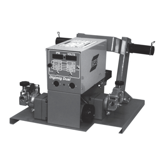
By virtue of its microprocessor controlled wire speed and Digimig wire feeder. Technical information and reference arc voltage design, the Digimig Dual allows the customer material is also provided to assist in troubleshooting. to preset both welding parameters (for each torch), lock- them-in, and be assured that each setting will be precisely 1.3 SPECIFICATIONS... - Page 6 RESET CIRCUIT BREAKER TRIGGER LOCK POWER ON- OFF SW. J1 CONTROL RECPT. RUN-SET KEY LEFT RIGHT TORCH GAS SOL TORCH CONNECTION GAS SOL CONNEC- TION LOCATION FOR OPT. POWER CABLE WATER CONNECTIONS ADAPTOR BLOCK Fig. 1-1 - Digimig Dual Feeder...
- Page 7 SECTION 1 DESCRIPTION ductor with Amphenol to Amphenol plugs; order one of the Regulator/Flowmeters: following: R-5007 Argon/Helium/Nitrogen, P/N 998124. R-5008 C0 , P/N 998125. 6-foot. 19-cond., P/N 30686. Gas Hoses: 30-foot, 19-cond., P/N 30780. Standard Duty, 40V77 (12-1/2-ft.) or P/N 34V38 (25-ft.) 60-foot, 19-cond., P/N 30781.
-
Page 8: Optional Accessories
SECTION 1 DESCRIPTION 1.5 OPTIONAL ACCESSORIES G. WC-9 Coolant Circulator (P/N 33540) is used for A. Water Kit (P/N 994466). Permits the convenient water cooled torch operation and is designed to be connection of water-cooled torches and continuous “free standing” in a convenient location near the torch. water supply to the wire feeder. -
Page 9: Installation
SECTION 2 INSTALLATION REGULATOR/ WATER "IN" HOSE - 40V76 REGULATOR/ FLOWMETER (12 1/2 FT.) FLOWMETER GAS HOSE GAS HOSE 40V77 (12-1/2 FT.) 40V77 (12-1/2 FT.) 34V38 (25 FT.) 34V38 (25 FT.) PLAN VIEW DUAL FDR. WATER KIT - 994466 GAS SOLENOIDS WATER "DRAIN"... - Page 10 TO WORK* across the room. SOURCE HOOKUP † ESAB will not honor the warranty on Digimigs that are used with non- 1. Remove “hairpin” clip from spindle. ESAB manufactured interconnect cables and sustain damage that 2. Position the spool of wire so that when it is placed on in ESAB’s opinion is caused by these cables.
-
Page 11: Operation
SECTION 2 INSTALLATION adjustment can be made after the wire feed is put into F. WATER KIT (Optional see Fig. 6-7) operation. Note that a light silver-colored spring Mount bulkhead adaptor (58V75) behind opening pro- (182W55) is installed on the accessory support for vided in rear vertical support plate, below gas connec- use with soft and small diameter hard wire. - Page 12 SECTION 3 OPERATION ture. This time period will be set In one-cycle (60 4. Digital Readout Windows. Two individual three- cycle = 1 sec.) Increments. When set to “zero”, digit windows are provided to display preset or actual the Automatic Anti-stick feature will be opera- welding parameters as follows: tional.
- Page 13 SECTION 3 OPERATION code “3” is for the 5000 aluminum series of wires. displayed in the IPM and VOLTS windows respec- (2) Wire Diameter. This parameter is displayed tively and are set as follows: in the right (VOLTS) window and offers a (1) Power source.
-
Page 14: Gas/Wire Adjustments
SECTION 3 OPERATION have a bearing on the quality of starts as f. Position 6, RUN Schedule I (Must be Set). This explained in Section 3.4-B-5. position allows you to preset the welding param- (2) After starting the welding sequence, if an eters (IPM/VOLTS) for Schedule I (RUN position). -
Page 15: Setting Up Torch Program Parameters
SECTION 3 OPERATION is reached. To feed the cold wire preset, you must b. Continue to hold the Purge position for approx. 15 actuate the INCH position of the Inch-Purge (Reset) seconds to insure adequate purging of each gas switch, with the accessory support closed. hose and torch. -
Page 16: Welding Operation
3.5. WELDING OPERATION NOTE: The control is designed to provide excellent After the desired welding modes have been weld-tested starting characteristics with the latest ESAB (with control to SET position) and satisfactory results inverter power sources. However, arc starting achieved, the program parameters can be "lock-in" by can be affected by many external factors such placing the key switch in the RUN (Lock-In) position. - Page 17 SECTION 3 OPERATION shutdown if preset wire speed or arc voltage parameters cannot be maintained due to an abnormal condition. If this occurs, the parameter causing the system shut- Positions down will be signaled by a flashing digital display window. To clear the shutdown/abort, activate the RE- SET position of the Inch-Purge (Reset) switch on the Pos.
-
Page 18: Troubleshooting
If a printed circuit (PC) board is determined B. No preset displays appear in windows. to be the problem check with your ESAB supplier for 1. Make sure the LED Display board harness/plug is a trade-in on a new PC board. Supply the distributor plugged into the P5 receptacle on the MPU board. - Page 19 NOTE: Prior to checking the servos, make sure the in the strobe pickup on the p.c. board. Digimig is connected to suitable ESAB power 3. If all items in step 2 are in order, and motor speed source in order to obtain the necessary o.c.v.
- Page 20 SECTION 4 TROUBLESHOOTING If the speed servo cannot be adjusted at all, the b. Place the Panel/Remote switch on the power problem may be in the J-Governor, and/or I/O, and/or source in PANEL position. MPU p.c. boards which need to be replaced as c.
- Page 21 SECTION 4 TROUBLESHOOTING...
-
Page 23: Maintenance
The serial number is when ordering replacement parts. stamped on the unit nameplate. To order parts by phone, contact ESAB at 1-803-664- 6.2 ORDERING 5540 or 4460. Orders may also be faxed to 1-800-634- 6548. - Page 24 SECTION 6 REPLACEMENT PARTS Fig. 6-1. DigiMig Dual Wire Feeder, P/N 30912 (Front View)
- Page 25 SECTION 6 REPLACEMENT PARTS Fig. 6-1. DigiMig Dual Wire Feeder, P/N 30912...
- Page 26 SECTION 6 REPLACEMENT PARTS TACH HOUSING - 18786 4.010 SQ. 11.6 (2) 8-32 X 3/8" Screw 2.25 TACH. P.C.B.D. Gear Case Lubricated with .020 2.370 Texac Multifak Grease 675429 2.000 (2) Screw-61324746 2.875 VENT PLUG .6251 TACH DISK 950313 2.86 MIN.
- Page 27 SECTION 6 REPLACEMENT PARTS Fig. 6-4 DigiMig Dual Control Assembly, P/N 30913...
- Page 28 SECTION 6 REPLACEMENT PARTS SHAFT - 60N65 CLAPPER - 60N98 KNOB - 60N68 LIGHT SPRING 182W55 (FOR ROLL PIN 1/4" X 1-3/4" LG SOFT & SMALL DIA. HARD WIRE) RETAINER 58N24 INLET FORK - 49V43 WIRE OUTLET GUIDE INSERT CONDUIT INLET WIRE GUIDE 29N13 OUTLET...
- Page 29 NOTES...
- Page 30 NOTES...
- Page 31 F-15-286 INSTRUCTIONS for December, 1995 REMOTE CONTROL KIT Item No. 36010 For V 452, V 582, V 652cvcc and V 782cvcc Power Sources 3. Remove the two screws from the upper corners of This kit, when installed, permits the use of the HC-3B the control panel on the power source and open Remote Pendant Control (I/N 33838) with the power the control panel.
- Page 32 ESAB Welding & Cutting Products, Florence, SC Welding Equipment COMMUNICATION GUIDE - CUSTOMER SERVICES A. CUSTOMER SERVICE QUESTIONS: Telephone: (800)362-7080 / Fax: (800) 634-7548 Hours: 8:00 AM to 7:00 PM EST Order Entry Product Availability Pricing Order Information Returns B. ENGINEERING SERVICE:...
Need help?
Do you have a question about the Digimig Dual and is the answer not in the manual?
Questions and answers