Table of Contents
Advertisement
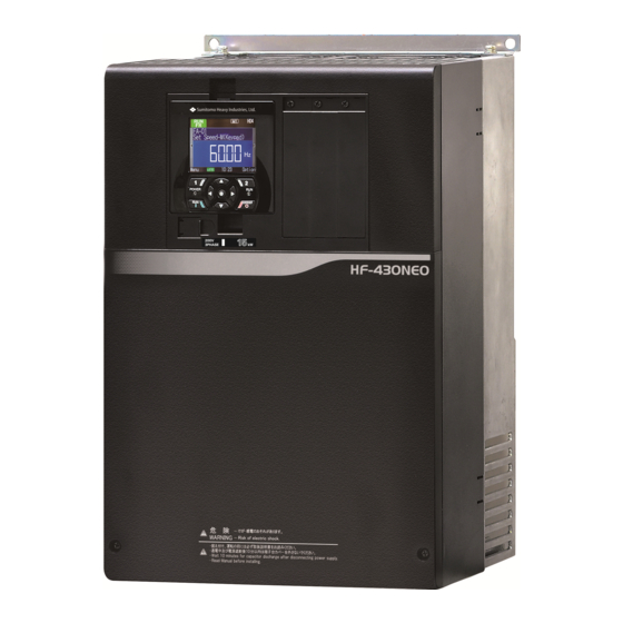
HF-430NEO
Screw type terminal option
Model : HF-TM2
Userʼs Guide
1. Make sure that this userʼs guide is delivered to the end user
of inverter unit.
2. Read the instruction manual and userʼs guide before installing or
operating the inverter unit, and store it in a safe place for reference.
Series
NOTICE
Userʼs Guide DM3413E
-1
Advertisement
Table of Contents

Related Manuals for Sumitomo HF-430NEO Series


Summary of Contents for Sumitomo HF-430NEO Series
- Page 1 HF-430NEO Series Screw type terminal option Model : HF-TM2 Userʼs Guide NOTICE 1. Make sure that this userʼs guide is delivered to the end user of inverter unit. 2. Read the instruction manual and userʼs guide before installing or operating the inverter unit, and store it in a safe place for reference. Userʼs Guide DM3413E...
- Page 2 Sumitomo. No patent liability is assumed with respect to the use of the information contained herein. Moreover, because Sumitomo is constantly striving to improve its high-quality products, the information contained in this manual is subject to change without notice.
-
Page 3: Introduction
Introduction Introduction Thank you for purchasing the HF-TM2: Screw type terminal option for HF-430NEO series inverter. This instruction manual describes how to handle and maintain the HF-TM2. Please read this manual carefully before using the HF-TM2, and keep it handy for those who operate, maintain and inspect it. -
Page 4: Table Of Contents
Table of Contents Table of Contents ● Introduction ............ S-1 ● Table of Contents .......... S-2 Chapter 1 Safety Precautions 1.1 About this chapter ........1-1 1.3 Symbol explanation ........1-2 1.2 Types of warnings ........... 1-1 1.4 Precautions ............. 1-2 Chapter 2 Overview 2.1 About this chapter .......... -
Page 5: Chapter 1 Safety Precautions
Chapter 1 Safety Precautions Chapter 1 Safety Precautions 1.1 About this chapter This chapter contains the information about Safety precautions during the installation, wiring, operation and inspection. Before installation, wiring, operation, inspection, or usage please read completely and fully understand this guide. - Page 6 Chapter 1 Safety Precautions 1.3 Symbol explanation In this guide, there are some explanatory notes using different symbols. Please pay attention to this content and keep in mind itsinformation. Symbol definition When handling this product, this symbol indicates danger, warning or caution about ignition, electric shock, high temperature or other dangers.
- Page 7 Chapter 1 Safety Precautions 1.4.2 Precautions during the installation! Danger ● Risk of Fire! Fire ・DO NOT place inflammable objects nearby Hazard ・DO NOT let scraps of wire, welding sputtering, irons scraps or other objects get inside the device. ・Avoid installing this device in places with high temperature, high humidity, Condensation-prone Prohibited conditions, dusty conditions, corrosive gas, explosive gas, flammable gas, grinding fluid mist, hydrogen sulfide or salt damage prone conditions.
- Page 8 Chapter 1 Safety Precautions ● Risk of an electric shock and/or fire! Electric ・Perform the wiring only after installing the inverter. shock Fire Warning ● Risk of Fire! Fire ・Tighten each screw to the specified torque. hazard ・No screw must be left loose. ・Make sure that the inverter and HF-TM2 are fixed together with the securing screw.
- Page 9 Chapter 1 Safety Precautions ● Risk of an electric shock! Electric ・Be sure to screw HF-TM2 before turning on the inverter power. shock ・Do not disconnect HF-TM2 while power is being supplied to the inverter or voltage remains inside. ・Do not operate switches with wet hands. Prohibited Warning ●...
- Page 10 Chapter 1 Safety Precautions 1.4.6 Precautions for disposal! Danger ● Risk of an injury and/or an explosion! ・Outsource to a qualified industrial waste disposal contractor when discarding this device. Injury and Disposing of this device on your own may result in the production of poisonous gas. explosion hazard ・A qualified waste disposer includes industrial waste collector/transporter and industrial waste...
-
Page 11: Chapter 2 Overview
Chapter 2 Overview Chapter 2 Overview 2.1 About this chapter This chapter includes explanations of applicable products, knowledge required for reading the guide, those who should read the guide, and the purpose, overview and glossary of the Guide 2.2 Applicable devices The contents of this guide are applicable to HF-TM2. - Page 12 Chapter 3 Enclosed Items Chapter 3 Enclosed Items 3.1 About this chapter This chapter describes bundled items that need to be checked upon purchase. 3.2 About the enclosed items The following items are included in the package. User's guide x1 HF-TM2 x1 3.3 Verification after the purchase ・Please verify the items written on the right when unpacking.
- Page 13 Chapter 4 Installation and Wiring Chapter 4 Installation and Wiring 4.1 About this chapter This chapter describes installation of HF-TM2 and wiring to HF-TM2. 4.2 Installation of HF-TM2 Installation procedure ① Remove the terminal cover of HF-430NEO and confirm the control terminal like the following picture (Fig.
- Page 14 Chapter 4 Installation and Wiring ③ The following picture (Fig. 3) shows the terminal space after removing the standard control terminal board. Fig.3 ④ Align the connector of logic board with the connector of HF-TM2. And then connect HF-TM2 to the direction of the arrow (Fig.4). Fig.4 Direction to install ⑤...
-
Page 15: Wiring Of Hf-Tm2
Chapter 4 Installation and Wiring 4.3 Wiring of HF-TM2 ■Outline of control circuit HF-TM2 Terminals Alarm relay 1C contact Equipment like Lamp, relay, PLC, RY Relay Input terminal Output terminal (Open collector) * Supporting sink/source DC24 ※When using source logic, connect the shield to BC. - Page 16 Chapter 4 Installation and Wiring ■Precaution at wiring to HF-TM2 • COM and BC are common terminals for input and output signals, and they are insulated from one another. Electric shock Do not make these common terminals shorted or grounded. Failure •...
-
Page 17: Hf-Tm2 Terminal Arrangement
Chapter 4 Installation and Wiring 4.4 HF-TM2 Terminal arrangement HF-TM2 Terminals +V Jumper (Default position) Logic of input terminals In the factory setting, the logic for input terminals is the sink logic. To switch the input control logic to the source logic, remove the jumper connecting terminals P24 and PCS on the control circuit block, and then connect terminals PCS and BC with the jumper. - Page 18 Chapter 4 Installation and Wiring • Regarding to the default setting of parameters for each terminal function, refer to the user′s guide for HF-430NEO. • Refer to “4.3 Wiring of HF-TM2” as wiring sample. ■Output terminals (M3 screw terminal) Terminal Terminal Description Electrical characteristics...
- Page 19 Chapter 4 Installation and Wiring • Regarding to the default setting of parameters for each terminal function, refer to the user′s guide for HF-430NEO. • Refer to “4.3 Wiring of HF-TM2” as wiring sample. ■External Thermistor (M3 screw terminal) Terminal Terminal Electrical Description...
- Page 20 Chapter 4 Installation and Wiring • Regarding to the default setting of parameters for each terminal function, refer to the user′s guide for HF-430NEO. • Refer to “4.3 Wiring of HF-TM2” as wiring sample. ■Serial communication (Spring clamp terminal) Terminal Electrical Terminal name Description...
- Page 21 Chapter 4 Installation and Wiring ■Emergency stop function (disabled by the factory setting • The emergency stop function shuts off the inverter output in response to a command from a hardware circuit via an intelligent input terminal without the operation by internal CPU software. When using this function, refer to the user′s guide for HF-430NEO.
- Page 22 Chapter 5 Precaution for using HF-TM2 Chapter 5 Precaution for using HF-TM2 5.1 About this chapter This chapter contains the information about the precautions at using HF-TM2 and the affected parameters. 5.2 Precaution for using HF-TM2 Table 1 Comparison between HF-430NEO standard terminal and HF-TM2 Function Standard HF-TM2...
-
Page 23: List Of Affected Parameter Modes
Chapter 5 Precaution for using HF-TM2 5.3 List of affected parameter modes Some functions of terminals become invalid when HF-TM2 is connected. Please confirm the parameters. Code Function name Difference dA-51 Input terminal monitor Terminal [DFH] and [DHH] are always “L”. dA-54 Output terminal monitor No actual output from terminal [RL]... - Page 24 Warranty Warranty Warranty The warranty shall be 18 months from date of shipment or 12 months after initial period operation, whichever is shorter. In the event that any problem or damage to the Product arises during the “Warranty Period” from defects in the Product whenever the Product is properly installed and combined with the Buyer’s equipment or machines maintained as specified in the maintenance manual, and properly operated under the conditions described in the catalog or as otherwise agreed upon in writing between the Seller and Buyer or its...
- Page 25 SM-Cyclo Italy Srl (SMIT) Sumitomo Industrias Pesadas do Brasil Ltda. (SHIB) Via dell' Artigianato 23, 20010 Cornaredo (MI), Italy Sumitomo (SHI) Cyclo Drive Asia Paci c Pte. Ltd. Philippines Branch O ce (SMPH) Rodovia do Acucar (SP-075) Km 26 TEL (39)293-481101...
Need help?
Do you have a question about the HF-430NEO Series and is the answer not in the manual?
Questions and answers