Table of Contents

Related Manuals for Sumitomo CAI40C


Summary of Contents for Sumitomo CAI40C
- Page 1 Inverter CAI Series CAI 40/90 C Type CAUTION Carefully read the "Safety Precautions" in the introduction before reading the text of the operation manual in order to thoroughly understand the contents for correct use. Operating and Maintenance Manual EM0102E...
-
Page 2: Table Of Contents
[Contents] Safety Precautions ............1 Standard specifications ..........6 Outline drawing .............. 7 Installation ............... 8 Wiring ................10 Operation ................. 12 Alarm output ..............17 Maintenance and inspection ......... 18 [Check the contents of packing] Inveter Operation CAI40C/CAI90C Manual... -
Page 3: Safety Precautions
[ Safety Precautions ] Carefully read this operation manual for correct use before installa- tion, operation, maintenance, and inspection. Thoroughly understand the machine, safety information, and precautions before use. Safety precautions are classified into "DANGER" and "CAUTION" in this manual. : Improper handling entails danger, possibly leading to death or serious DANGER... - Page 4 1. Confirmation of actual product CAUTION Do not operate the machine with a damaged inverter or an in- verter with some missing parts, otherwise injury may result. 2. Installation CAUTION Attach the machine to metal or other nonflammables, otherwise a fire may break out.
- Page 5 3. Wiring DANGER Check that the input power is OFF before wiring, otherwise an electric shock or fire may result. Be sure to install a magnetic circuit breaker (NFB), otherwise a fire may break out. Be sure to ground the grounding terminal , otherwise an electric shock or fire may result.
- Page 6 4. Operation DANGER Be sure to attach the case cover before turning the power on. Do not remove the case cover during power supply, otherwise an elec- tric shock may result. Do not operate switches with wet hands, otherwise an electric shock may result.
-
Page 7: Maintenance And Inspection
5. Maintenance and inspection DANGER This inverter has a high-voltage terminal, which is dangerous. Do not touch it, otherwise an electric shock may result. Conduct maintenance or inspection five minutes or more after the input power is turned off, otherwise an electric shock may result. Leave maintenance and inspection to a specialist. -
Page 8: Standard Specifications
1. Standard specifications Product name CAI40C CAI90C Applicable type of motor 3-phase induction motor Applicable motor output (W) 25/40 60/90 Specification Conforming to CE mark UL Frequency (Hz) 1.0~120Hz 106/152 212/303 Output capacitance (VA) Output Output current (A) 0.28/0.4 0.56/0.8... -
Page 9: Outline Drawing
2. Outline drawing Outline drawing CAI40C Weight of main unit 0.30kg 125.1 60.0 137.1 52.5 AC INVERTER POWER ALARM RS485 STOP RS485 CAI90C Weight of main unit 0.47kg 125.1 60.0 137.1 52.5 AC INVERTER POWER ALARM RS485 STOP RS485 Unit: mm... -
Page 10: Installation
3. Installation 3-1 Installation dimensions/method Refer to p.7 for the outside dimensions. Refer to Fig.(a) when installing the machine. Machine the installa- tion surface as shown in Fig.(b). (DIN rail cannot be attached.) Secure the machine without a gap between the machine and the mounting surface by using the mounting hole in the con- trol unit. - Page 11 3-2 Place of installation 10cm 10cm 10cm 10cm 10cm 10cm Set the machine vertically Install in places with no cor- and provide a space for ven- rosive gas or grinding fluid. tilation around the ma- chine. The machine is not of a wa- terproofing structure.
-
Page 12: Wiring
4. Wiring 4-1 Standard connection diagram Input power Motor output External speed setting signal Frequency setter Terminal for main circuit Terminal for control circuit Voltage input Shielded wire Common (or twisted wire) Run/Stop Forward/reverse rotation Natural/braking stop Error signal output terminal Open collector Common Communication port... - Page 13 CAUTION 4-3 Precautions as to wiring 1) Main circuit 1. Do not connect the power input terminal and motor output terminals (U, V, and W) reversely. 2. Do not ground the motor output terminals (U, V, and W). Check that the motor output terminals are not grounded before turn- ing the power on.
-
Page 14: Operation
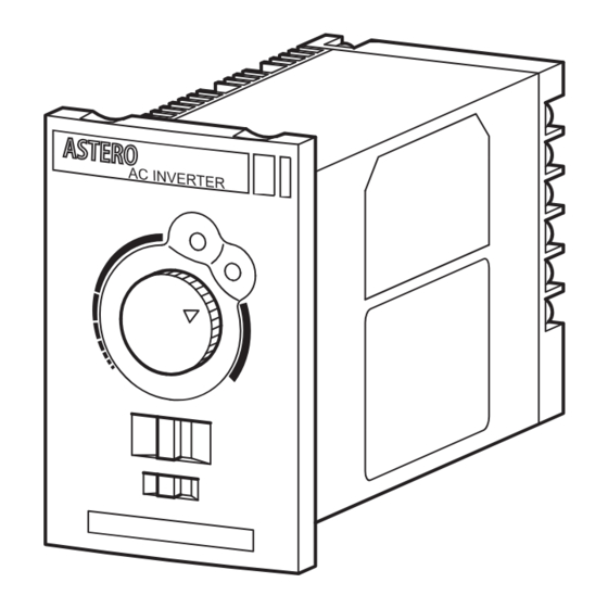
5. Operation 5-1 Front panel POWER LED Comes on when power is supplied. ALARM LED Blinks when the protective function is in operation. (Refer to p.15 for details.) Front panel volume (Refer to p.14 for details.) Operation stop switch STOP; RUN Forward/reverse rotation switch (Usable in the panel mode. - Page 15 Accel/Decel Time(sec) 5-2 Internal panel Accel/Decel Time knob(sec) ACC/DES 60Hz 50Hz 30(S) Unit 0.05 REV EN REV DIS LO TQUE HI THM POWER PANEL LOCAL REMO TE ALARM 60Hz 50Hz REV EN REV DIS LO TQUE HI THM PANEL LOCAL REMOTE STOP Dip switch setting...
- Page 16 Try to operate. When using the front panel for operation Step 1 Primary power ON (Power LED ON) Step 2 Determine the direction of rotation. (FWD or REV) Step 3 Set to RUN. Step 4 Set the speed of rotation. (Adjust) (Unnecessary when the speed is set in advance.)
-
Page 17: Alarm Output
6. Alarm output 6-1 Protective function When the following functions are activated, the inverter output is stopped. Check the details of respective alarms, and take corrective measures. Be sure to turn off the power before taking corrective measures. Protective Contents LED blinking pattern Correction function... -
Page 18: Maintenance And Inspection
6-2. Resetting when protective function is activated Reset the protective function by any one of the following methods. 1. Turn off the input power. 2. Set the operation stop switch on the front panel in the STOP posi- tion. 3. Set the external control terminal “RUN” in the STOP (OFF) position. 4. - Page 19 8. Precautions as to operation CAUTION 8-1 Precautions as to use (1) A high-voltage circuit is provided on the printed circuit board. Never touch it by hand. (2) The internal circuit remains charged with high voltage for some time after the power is turned off. Wait for one minute after turning off the power before inspection.
- Page 20 (12)The operator must check for the safety of the surrounding before turning on or off the power. Prevent operation by any person who is not concerned. (13) If the supply voltage drops when the power supply is interrupted instantaneously, the inverter will detect the undervoltage and shut off the output.
- Page 21 that case, use an earth leakage breaker, which is made to pre- vent high harmonics from reaching an inverter, in the system in question and other systems. (8) This inverter is for 3-phase induction motors. Do not use the inverter for single-phase motors. (9) When using the inverter for parallel operation of more than one motor, select an appropriate inverter capacity so that the total rated current will be lower than the rated current of the inverter.
- Page 22 Warranty The scope of our warranty for our products is limited to the range of our manufacture. Warranty (period and contents) Warranty Period The warranty period for the new Products shall be 18 months after the shipment of the Products from the seller's works or 12 months from the Products coming into operation, whether comes first.
- Page 23 EM0102E-1.5 Printed 2009.12...
Need help?
Do you have a question about the CAI40C and is the answer not in the manual?
Questions and answers