Table of Contents
Advertisement
Quick Links
Advertisement
Table of Contents

Subscribe to Our Youtube Channel
Related Manuals for Sumitomo CAI Series


Summary of Contents for Sumitomo CAI Series
- Page 1 Inverter CAI Series (CAI 40/90 C Type) CAUTION Carefully read the “Safety Precautions” in the introduction before reading the text of the operation manual in order to thoroughly understand the contents for correct use. Operation Manual EM0102E-4...
-
Page 2: Table Of Contents
[Contents] Safety Precautions ................... 1 1. Standard specifications ................6 2. Outline drawing ..................7 3. Installation ....................8 4. Wiring ......................10 5. Operation ....................12 6. RS485 Serial Communication ............. 15 7. Alarm output ..................... 22 8. Maintenance and inspection ............... 23 9. -
Page 3: Safety Precautions
[ Safety Precautions ] Carefully read this operation manual for correct use before installation, operation, maintenance, and inspection. Thoroughly understand the inverter, safety information, and precautions before use. Safety precautions are classified into "DANGER" and "CAUTION" in this manual. : Improper handling entails danger, DANGER possibly leading to death or serious injury. - Page 4 (1) Confirmation of actual product CAUTION Do not operate the machine with a damaged inverter or an inverter with some missing parts, otherwise injury may result. (2) Installation CAUTION Attach the inverter to metal or other nonflammables, otherwise a fire may break out. Do not place the inverter near inflammables, otherwise a fire may break out.
- Page 5 (3) Wiring DANGER Check that the input power is OFF before wiring, otherwise an electric shock or fire may result. Be sure to install a magnetic circuit breaker (MCB), otherwise a fire may break out. Be sure to ground the grounding terminal , otherwise an electric shock or fire may result.
- Page 6 (4) Operation DANGER Be sure to attach the case cover before turning the power on. Do not remove the case cover during power supply, otherwise an electric shock may result. Do not operate switches with wet hands, otherwise an electric shock may result.
- Page 7 (5) Maintenance and inspection DANGER This inverter has a high-voltage terminal, which is dangerous. Do not touch it, otherwise an electric shock may result. Conduct maintenance or inspection five minutes or more after the input power is turned off, otherwise an electric shock may result. Leave maintenance and inspection to a specialist.
-
Page 8: Standard Specifications
1. Standard specifications Product name CAI40C CAI90C Applicable type of motor 3-phase induction motor Applicable motor output (W) 25/40 60/90 Specification Conforming to CE mark and cUL Note:1 Frequency (Hz) 1.0~120Hz Output capacity (VA) 106/152 212/303 Output rating Output current (A) 0.28/0.4 0.56/0.8 Two times for 100 V class input Proportional to... -
Page 9: Outline Drawing
2. Outline drawing Outline drawing CAI40C Weight of unit 0.30kg 125.1 60.0 137.1 52.5 AC INVERTER POWER ALARM RS485 STOP RS485 CAI90C Weight of unit 0.47kg 125.1 60.0 137.1 52.5 AC INVERTER POWER ALARM RS485 STOP RS485 Unit: mm - 7 -... -
Page 10: Installation
3. Installation 3.1 Installation dimensions/method Refer to Fig.(a) when installing the inverter. The inverter of the installation surface as shown in Fig.(b). (DIN rail cannot be attached.) Refer to p.7 for the outside dimensions. Fig.(a) Fig.(b) Secure the inverter without a gap between the inverter and the mounting surface by using the mounting hole in the inverter. - Page 11 3.2 Place of installation 10cm 10cm 10cm 10cm 10cm 10cm Set the inverter vertically and Install in places with no provide a space for ventilation corrosive gas or grinding fluid. around the inverter. The inverter is not of a Avoid hot or humid places or waterproofing structure.
-
Page 12: Wiring
Magnetic circuit Mitsubishi breaker (MCB) Electric CA190C for 100V input and 200V input BL-2C 6A when 100W class motor is used. AC reactor ET682WW-01 All models Sumitomo Noise filter ET681WW-01 All models Heavy Frequency Industries EVR-01 All models setting unit (VR) - Page 13 CAUTION 4.3 Precautions as to wiring (1) Main circuit 1) Do not connect the power input terminal and motor output terminals (U, V, and W) reversely. 2) Do not ground the motor output terminals (U, V, and W). Check that the motor output terminals are not grounded before turning the power on.
-
Page 14: Operation
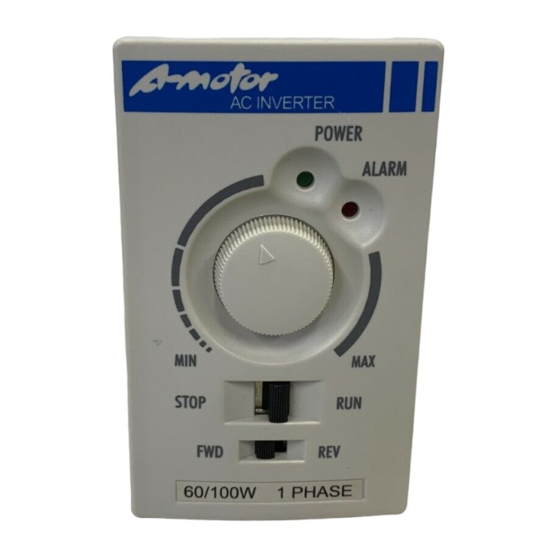
5. Operation 5.1 Front panel POWER LED Lights while the power is ON. ALARM LED Blinks when the protective function is in operation. (Refer to p.15 for details.) Potentiometer (Refer to p.14 for details.) RUN and STOP Switch STOP; RUN Forward/Reverse Switch (Usable in the panel mode. - Page 15 5.2 Internal panel Accel/Decel Time(s) Accel/Decel Time knob(s) ACC/DES 60Hz 50Hz 30(S) Unit 0.05 REV EN REV DIS LO TQUE POWER HI THM PANEL LOCAL REMO TE ALARM Enlarged view 60Hz 50Hz REV EN REV DIS LO TQUE HI THM PANEL LOCAL REMOTE...
- Page 16 < Try to operate > • When using the front panel for operation Step 1 Primary power ON (Power LED ON) Step 2 Determine the direction of rotation. (FWD or REV) Step 3 Set to RUN. Step 4 Set the speed of rotation. (Ad j u s t m e nt u s i n g t h e potentiometer) Front...
-
Page 17: Rs485 Serial Communication
6. RS485 Serial Communication Serial communication with the external control device is possible using the RS485 communication port (RJ11) on the back side for the inverter. Pin assignment of RJ11 connector Signal Contents Reference +15V +15Vdc Power supply +15Vdc Ground SG–... - Page 18 6.3 Setting for the Inverter Address (DIP Switch) For RS485 communication, set the DIP switch 7 to ON. ( In this case, you will not be able to drive on the front panel and terminals. ) DIP switch 1 to 6 is used to set the inverter address. Refer to the following setting example.
- Page 19 6.5 Communication Protocol 6.5.1 Frame Format Transmitted and Received Start data ‘ : ’ (ASCII code/3AH) ADR1 Communication address: Address information of 8 bits×2 that composes ASCII code ADR0 CMD1 Command code: Command information of 8 bits×2that composes ASCII code CMD0 Data structure: DATA (n-1) to 0...
- Page 20 6.5.2 Parameter Table Setting Data Address Parameter Name Data Contents Initial (Decimal) Recognition code of the Setting Depend on the inverter inverter 0001 Rated current # . # 0002 Parameter reset Reset 50Hz 60Hz Max. output frequency 0003 setting 100Hz 120Hz Acceleration/Deceleration 0004...
- Page 21 6.5.3 List of Address Items Address Explanation Parameters nnnn: Address for parameters nnnnH of the Inverter (Set the address for parameters of the Inverter.) 00 : No function 01 : STOP bit 0, 1 10 : RUN 11 : No function 2000H bit 2, 3, 6 to 15 Unused (0)
- Page 22 6.5.4 Calculation for LRC (Longitudinal Redundancy Check) ‘ : ’ ADR1 ‘0’ ADR0 ‘1’ CMD1 ‘0’ CMD0 ‘3’ ‘2’ ‘1’ Starting data address ‘0’ ‘2’ ‘0’ ‘0’ Number of read data ‘0’ ‘2’ LRC CHK1 ‘D’ 01H + 03H + 21H + 02H + 00H + 01H = 29H LRC = 29H Complement = FF –...
- Page 23 6.5.6 List of Fault Code Fault Explanation Code Illegal command code: Command data other than those indicated by 03 and 06 is received. Illegal address data: Address data other than those indicated by 6.5.2 and 6.5.3 is received. Illegal data: Data other than those indicated by 6.5.2 and 6.5.3 is received.
-
Page 24: Alarm Output
7. Alarm output 7.1 Protective function When the following functions are activated, the inverter output is stopped. Check the details of respective alarms, and take corrective measures. Be sure to turn off the power before taking corrective measures. Protective Contents LED blinking pattern Correction function... -
Page 25: Maintenance And Inspection
7.2 Reset methods when protective function is activated Reset the protective function by any one of the following methods. (1) Turn off the input power. (2) Set the operation stop switch on the front panel in the STOP position. (3) Set the external control terminal “RUN” in the STOP (OFF) position. (4) Transmit the Reset command when RS485 is used. -
Page 26: Precautions As To Operation
9. Precautions as to operation CAUTION 9.1 Precautions as to use (1) A high-voltage circuit is provided on the printed circuit board. Never touch it by hand. (2) The internal circuit remains charged with high voltage for some time after the power is turned off. Wait for one minute after turning off the power before inspection. - Page 27 (13) If the supply voltage drops when the power supply is interrupted instantaneously, the inverter will detect the undervoltage and shut off the output. When the supply voltage is restored, the inverter automatically resumes operation. Check the system consistency. (14) The heat sink on the side of the inverter becomes hot. Never touch it during operation or before a sufficient time passes after the inverter is stopped.
- Page 28 (9) When using the inverter for parallel operation of more than one mo- tor, select an appropriate inverter capacity so that the total rated current will be lower than the rated current of the inverter. When the total of motor output is used for selection, the rated current of the inverter may be exceeded depending on the type of motor.
-
Page 29: Safety Guideline
10. Safety Guideline - 27 -... - Page 30 - 28 -...
- Page 31 - 29 -...
- Page 32 - 30 -...
- Page 33 - 31 -...
- Page 34 - 32 -...
- Page 35 Warranty The scope of our warranty for our products is limited to the range of our manufacture. Warranty (period and contents) The warranty period for the new Products shall be 18 months after the shipment Warranty of the Products from the seller's works or 12 months from the Products coming Period into operation, whether comes first.
- Page 36 Sumitomo Heavy Industries, Ltd. (SHI) ThinkPark Tower, 1-1 Osaki 2-chome, Shinagawa-ku, Southeast Asia / Oceania Tokyo 141-6025, Japan Sumitomo (SHI) Cyclo Drive Asia Paci c Pte. TEL (81)3-6737-2511 FAX (81)3-6866-5160 Ltd. (SCA) 15 Kwong Min Road, Singapore 628718 TEL (65)6591-7800 FAX (65)6863-4238 Specifications, dimensions, and other items are subject to change without prior notice.
Need help?
Do you have a question about the CAI Series and is the answer not in the manual?
Questions and answers