Table of Contents
Advertisement
Quick Links
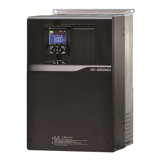
HF-430NEO
Analog Input/Output option
Model : P1-AG
Userʼs Guide
1. Make sure that this userʼs guide is delivered to the end user
of inverter unit.
2. Read the instruction manual and userʼs guide before installing or
operating the inverter unit, and store it in a safe place for reference.
Series
NOTICE
Userʼs Guide DM3412E
-1
Advertisement
Table of Contents

Related Manuals for Sumitomo HF-430NEO Series


Summary of Contents for Sumitomo HF-430NEO Series
- Page 1 HF-430NEO Series Analog Input/Output option Model : P1-AG Userʼs Guide NOTICE 1. Make sure that this userʼs guide is delivered to the end user of inverter unit. 2. Read the instruction manual and userʼs guide before installing or operating the inverter unit, and store it in a safe place for reference. Userʼs Guide DM3412E...
- Page 2 Sumitomo. No patent liability is assumed with respect to the use of the information contained herein. Moreover, because Sumitomo is constantly striving to improve its high-quality products, the information contained in this manual is subject to change without notice.
-
Page 3: Introduction
Introduction Introduction Thank you for purchasing the P1-AG: Analog Input/Output option for HF-430NEO series inverter. This instruction manual describes how to handle and maintain the P1-AG. Please read this manual carefully before using the P1-AG, and keep it handy for those who operate, maintain and inspect it. -
Page 4: Table Of Contents
Table of Contents Table of Contents ● Introduction ............ S-1 ● Table of Contents .......... S-2 Chapter 1 Safety Precautions 1.1 About this chapter ........1-1 1.3 Symbol explanation ........1-2 1.2 Types of warnings ........... 1-1 1.4 Precautions ............. 1-2 Chapter 2 Overview 2.1 About this chapter .......... -
Page 5: Chapter 1 Safety Precautions
Chapter 1 Safety Precautions Chapter 1 Safety Precautions 1.1 About this chapter This chapter contains the information about Safety precautions during the installation, wiring, operation and inspection. Before installation, wiring, operation, inspection, or usage please read completely and fully understand this guide. - Page 6 Chapter 1 Safety Precautions 1.3 Symbol explanation In this guide, there are some explanatory notes using different symbols. Please pay attention to this content and keep in mind itsinformation. Symbol definition When handling this product, this symbol indicates danger, warning or caution about ignition, electric shock, high temperature or other dangers.
- Page 7 Chapter 1 Safety Precautions 1.4.2 Precautions during the installation! Danger ● Risk of Fire! Fire ・DO NOT place inflammable objects nearby Hazard ・DO NOT let scraps of wire, welding sputtering, irons scraps or other objects get inside the device. ・Avoid installing this device in places with high temperature, high humidity, Condensation-prone Prohibited conditions, dusty conditions, corrosive gas, explosive gas, flammable gas, grinding fluid mist, hydrogen sulfide or salt damage prone conditions.
- Page 8 Chapter 1 Safety Precautions ● Risk of an electric shock and/or injury! Electric ・Perform the wiring only after installing the inverter. shock injury Warning ● Risk of an electric shock and/or injury! Electric ・DO NOT operate/switch any of the switches from the 4 pole DIP switch on this device.* shock When this device is shipped all switches are turned off.
- Page 9 Chapter 1 Safety Precautions ● Risk of an electric shock! Electric ・Make sure to fasten all the screws of this device before turning it on. DO NOT detach this device shock while it is energized or the inverter capacitors are still charged. ・Additionally DO NOT touch the inside of the inverter while the inverter capacitors are still charged.
- Page 10 Chapter 1 Safety Precautions 1.4.6 Precautions for disposal! Danger ● Risk of an injury and/or an explosion! ・Outsource to a qualified industrial waste disposal contractor when discarding this device. Injury and Disposing of this device on your own may result in the production of poisonous gas explosion ・Contact your sales agent if you need to get this device fixed.
-
Page 11: Chapter 2 Overview
Chapter 2 Overview Chapter 2 Overview 2.1 About this chapter This chapter specifies the devices that this guide will describe. Additionally, it contains information necessary to clearly understand this guide, the objectives of this guide. 2.2 Applicable devices The contents of this guide will apply to the P1-AG device. For information about the inverter please refer to the HF-430NEO user's guide or the instruction manual. - Page 12 Chapter 2 Overview 2.5 Guide outline This guide has the following structure. ● The chapter 1: Safety Precautions "Safety Precautions" contains the safety instructions for installing, wiring, operating, maintaining and inspecting this device. ● The chapter 2: Overview "Overview" contains information necessary to clearly understand this guide. ●...
-
Page 13: About This Chapter
Chapter 3 P1-AG Chapter 3 P1-AG 3.1 About this chapter This chapter contains the explanation about this device external features and information on the name plate. 3.2 P1-AG appearance and nomenclature An external view of this device is shown below. For installing this device, connectors and other parts refer to the chapter 5 "Installation and Wiring". -
Page 14: Dimensions After Installed
Chapter 3 P1-AG 3.4 Dimensions after installed The dimensions of this device after it is installed on the HF-430NEO are shown in the image below. As shown on the image a part of this device will stand out from the HF-430NEO. Please be cautious when installing the P1-AG. -
Page 15: Verification After The Purchase
Chapter 4 Enclosed Items Chapter 4 Enclosed Items 4.1 About this chapter This chapter contains information about the items enclosed with the P1-AG. Additionally, it is explained how to inspect and verify this product after its purchase. 4.2 About the enclosed items ・Enclosed items Name label x1 Connector x1... - Page 16 Chapter 5 Installation and Wiring Chapter 5 Installation and Wiring 5.1 About this chapter This chapter contains information for installing and wiring this device on the HF-430NEO. For information about the HF-430NEO installation, please refer to the HF-430NEO user's guide. Additionally, when doing any work or operation, always follow the safety instructions and cautions given in the chapter 1.
- Page 17 Chapter 5 Installation and Wiring 5.2.2 How to install For explanation purposes, it will be assumed that the P1-AG is going to be installed in the SLOT1. (1) Remove the cover of the option cassette connection slot. Despite the removed cover will no longer be needed, it is recommended to keep it in a safe place.
- Page 18 Chapter 5 Installation and Wiring (3) Secure the P1-AG with the screw removed in procedure (1). Option cassette connection slots SLOT1 SLOT2 SLOT3 RJ45 Keypad Fasten the screw. USB(micro-B) (4) Connect the FG terminal to functional ground. Option cassette connection slots SLOT1 SLOT2 SLOT3 RJ45...
-
Page 19: Terminal Block And Wiring
Chapter 5 Installation and Wiring 5.3 Terminal block and wiring Terminal arrangement, symbols and specifications of P1-AG are shown the followings. ■Terminal arrangement ■Terminal specifications Terminal Name Symbol Description Electrical Characteristic Voltage input 4: Input impedance: 10kΩ(approximately) Analog Input 0 to 10V Allowable range of input: -0.3 to 12V Terminal 4 Current input 4:... - Page 20 Chapter 5 Installation and Wiring ■Recommendation terminals In order to make convenience to wiring and improve the connection, it's recommended to use the ferrule terminals with the following specifications for signal wire. Wire diameter Ferrule terminal L1[mm] L2[mm] φd[mm] φD[mm] ] (AWG) model *1) 0.25 (24)
- Page 21 Chapter 6 Functions of Analog Input/Output Function of Analog Chapter 6 Input/Output 6.1 About this chapter This chapter contains the information about the inverter setting parameters related to this product. 6.2 Terminal connection An example of terminal connection of P1-AG is as follows. Analog Input 4 voltage Analog Output 3 voltage Analog Input 5 voltage...
-
Page 22: List Of Parameters Related To The P1-Ag
Chapter 6 Functions of Analog Input/Output 6.3 List of parameters related to the P1-AG The following table shows the inverter setting parameters related to this product. For information about actual usage, please refer to the HF-430NEO User's guide. ■Parameter Code Parameter name Code Parameter name... -
Page 23: Inverter Troubleshooting
Chapter 7 Troubleshooting Chapter 7 Troubleshooting 7.1 About this chapter This chapter contains the troubleshooting of cases such as errors detected by the protection function, warnings given by the warning function, or some cases in which the device is not working properly. When the device is not working properly or there is any trouble, read this chapter before trying to solve the problem. - Page 24 Chapter 7 Troubleshooting ■Abnormality and its solutions related with this product. E060 / E069 Option 1 Error 0 / 9 E070 / E079 Option 2 Error 0 / 9 E080 / E089 Option 3 Error 0 / 9 When a communication error occurring between the P1-AG and the inverter, the inverter trips with those codes.
-
Page 25: Any Other Trouble
Chapter 7 Troubleshooting 7.4 Any other troubles In case the P1-AG does not work properly without any error codes of the inverter, refer to the following solutions. Issue▶ Possible cause▶ Possible solution ・When a communication error occurring between the P1- AG and the inverter, the P1-AG outputs 0V or 0mA in ・The P1-AG is not The function of... -
Page 26: Device Specifications
Chapter 8 Specifications Chapter 8 Specifications 8.1 About this chapter This chapter contains information about the P1-AG specifications. 8.2 Device specifications ■Specifications Item Specification Model P1-AG Weight 170 g Ambient operating temperature -10 to 50℃ Ambient operating humidity 20 to 90%RH No icing or condensation conditions. - Page 27 Warranty Warranty Warranty The warranty shall be 18 months from date of shipment or 12 months after initial period operation, whichever is shorter. In the event that any problem or damage to the Product arises during the “Warranty Period” from defects in the Product whenever the Product is properly installed and combined with the Buyer’s equipment or machines maintained as specified in the maintenance manual, and properly operated under the conditions described in the catalog or as otherwise agreed upon in writing between the Seller and Buyer or its...
- Page 28 SM-Cyclo Italy Srl (SMIT) Sumitomo Industrias Pesadas do Brasil Ltda. (SHIB) Via dell' Artigianato 23, 20010 Cornaredo (MI), Italy Sumitomo (SHI) Cyclo Drive Asia Paci c Pte. Ltd. Philippines Branch O ce (SMPH) Rodovia do Acucar (SP-075) Km 26 TEL (39)293-481101...
Need help?
Do you have a question about the HF-430NEO Series and is the answer not in the manual?
Questions and answers