Sign In
Upload
Download
Table of Contents
Contents
Add to my manuals
Delete from my manuals
Share
URL of this page:
HTML Link:
Bookmark this page
Add
Manual will be automatically added to "My Manuals"
Print this page
×
Bookmark added
×
Added to my manuals
Manuals
Brands
Sumitomo Manuals
Inverter
SF-320
Manual
Sumitomo SF-320 Manual
General-purpose compact inverter, v/f control-sensorless vector control, 200/400v class 0.2/0.4-7.5kw
Hide thumbs
1
2
3
4
5
6
7
8
9
10
11
12
13
14
15
16
17
18
19
20
21
22
23
24
25
26
27
28
29
30
31
32
33
34
35
36
Table Of Contents
37
page
of
37
Go
/
37
Contents
Table of Contents
Bookmarks
Table of Contents
List of Functions
Setting Range
Explanation of Operation Panel
Method of Operation
Explanation of Functions
Protective Functions
Terminal Functions
Main Circuit Terminals
Control Circuit Terminal
Basic Connection Diagram
Connection Diagram
Reference Circuit
Dimensional Drawings
Noise Filter
Leakage Current
Peripheral Equipment
Warranty
Safety Precautions
Advertisement
Quick Links
1
List of Functions
2
Setting Range
3
Method of Operation
4
Explanation of Operation Panel
5
Explanation of Functions
6
Protective Functions
7
Terminal Functions
8
Control Circuit Terminal
Download this manual
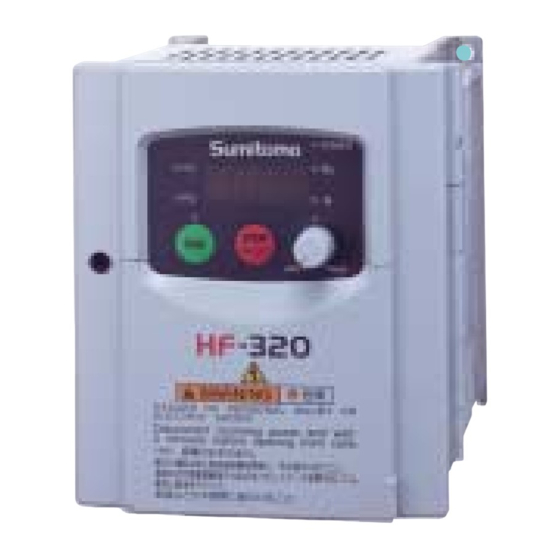
General-purpose Compact Inverter
V/F CONTROL-SENSORLESS VECTOR CONTROL
POWER TRANSMISSION & CONTROLS GROUP
SF
&
200V class 0.2–7.5kW
400V class 0.4–7.5kW
The Available Solution
HF
Cat . No.
D1001E-
1
Table of
Contents
Previous
Page
Next
Page
1
2
3
4
5
Advertisement
Table of Contents
Need help?
Do you have a question about the SF-320 and is the answer not in the manual?
Ask a question
Questions and answers
Related Manuals for Sumitomo SF-320
Inverter Sumitomo HF-320 Manual
General-purpose compact inverter, v/f control-sensorless vector control, 200/400v class 0.2/0.4-7.5kw (37 pages)
Inverter Sumitomo HF-430 Series Operating And Maintenance Manual
General-purpose high-performance inverter (136 pages)
Inverter Sumitomo HF-520 Series Operating And Maintenance Manual
Sensorless vector control inverter (272 pages)
Inverter Sumitomo HF-520 Series Manual
Sensorless vector inverter (27 pages)
Inverter Sumitomo HF-520 Technical Manual
Option cc-link (35 pages)
Inverter Sumitomo HF-430NEO Series User Manual
Screw type terminal option model : hf-tm2 (25 pages)
Inverter Sumitomo CAI40C Operation Manual
Cai series (23 pages)
Inverter Sumitomo CAI Series Operation Manual
(36 pages)
This manual is also suitable for:
Hf-320
Table of Contents
Save PDF
Print
Rename the bookmark
Delete bookmark?
Delete from my manuals?
Login
Sign In
OR
Sign in with Facebook
Sign in with Google
Upload manual
Upload from disk
Upload from URL


Need help?
Do you have a question about the SF-320 and is the answer not in the manual?
Questions and answers