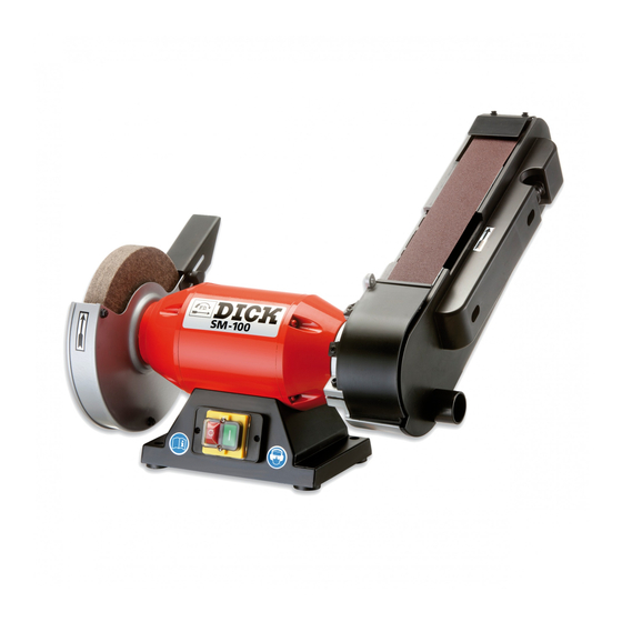
Dick SM-100 Operating Instructions Manual
Belt grinder 1-230 v - 50 hz
Hide thumbs
Also See for SM-100:
- Operating instructions manual (36 pages) ,
- Operating instructions manual (40 pages)
Table of Contents
Advertisement
Available languages
Available languages
Quick Links
Advertisement
Chapters
Table of Contents

Related Manuals for Dick SM-100


Summary of Contents for Dick SM-100
- Page 1 Betriebsanleitung (Original) SM-100 ~230 V - 50 Hz Bandschleifmaschine Friedr. Dick GmbH & Co. KG · Postfach 1173 · 73777 Deizisau · GERMANY · Tel.: +49 (0)7153-817-0 · Fax: +49 (0)7153-817-218/-219 · Web: www.dick.de · Mail: mail@dick.de ·...
- Page 2 © 2011 Firma Friedr. Dick GmbH & Co. KG. Diese Betriebsanleitung ist urheberrechtlich geschützt; alle üblichen Rechte vorbehalten. Vervielfältigung dieser Betriebsanleitung, auch auszugsweise, ist nur mit Ge- nehmigung der Firma Friedr. Dick GmbH & Co. KG gestattet. Zuwiderhandlun- gen verpflichten zu Schadenersatz und können strafrechtliche Folgen haben.
-
Page 3: Table Of Contents
8.1 Werkstücke schleifen ................25 Schleifzonen..................25 8.2. Werkstücke polieren................28 9. Wartung und Pflege ..............29 9.1 Bandschleifmaschine reinigen............... 29 9.2 Schleifband wechseln................29 9.3 Polierscheibe wechseln................. 31 10. Ersatzteile..................33 10.1Ersatzteilzeichnung ................33 10.2.Ersatzteile bestellen ................34 11. EG-Konformitätserklärung............35 Bandschleifmaschine SM-100... -
Page 4: Benutzerhinweise
Die technischen Informationen und Bedienungshinweise in dieser Betriebsanleitung entsprechen dem letzten Stand bei Auslieferung der Bandschleifmaschine. Konstruktive Weiterentwicklungen und Änderungen bleiben der Firma Friedr. Dick GmbH & Co. KG vorbe- halten. Alle Richtungsangaben sind bezogen auf den Blickwinkel des Bedieners. -
Page 5: Aufzählungen
Dieses Symbol kennzeichnet einen Warnhinweis, der unbedingt beachtet werden muss. • Mehr zur Bedeutung der Warnhinweise im Kapitel Sicherheit. GEBOT Diese Symbol kennzeichnet Handlungsanweisungen, die aus Sicherheitsgründen eingehalten werden müssen. HINWEIS, TIPP Dieses Symbol kennzeichnet allgemeine Hinweise, die Anwen- dungstipps und nützliche Informationen enthalten. Bandschleifmaschine SM-100... -
Page 6: Lieferumfang
Vor der Rücksendung der Ware auf die Antwort des Herstellers warten, um die nötigen Schritte einleiten zu können. Die Firma Friedr. Dick GmbH & Co. KG übernimmt keine Trans- portkosten für Rücksendungen, die nicht angewiesen wurden. Den Originalkarton für eventuell nötige Rücksendungen aufbe- wahren, damit keineTransportschäden bei der Rücksendung ent-... -
Page 7: Produkthaftung
Genehmigung der Firma. Für Mängel oder Schäden, die durch fehlerhafte Montage bzw. unsachgemäße Handhabung entstanden sind, übernimmt die Firma Friedr. Dick GmbH & Co. KG keine Haftung. Weitere Angaben zur Gewährleistung entnehmen Sie bitte den all- gemeinen Verkaufs-, Liefer- und Zahlungsbedingungen. -
Page 8: Sicherheit
VORSICHT Möglicherweise gefährliche Situation • Leichte Verletzungen können die Folge sein. Bestimmungsgemäße Verwendung Die Bandschleifmaschine SM-100 ist ausschließlich für den gewerblichen Gebrauch konzipiert. Die Bandschleifmaschine SM-100 kann zum handgeführten Trockenschleifen und Polieren von gereinigten Handmessern und Schneidwerkzeugen verwendet werden. Jegliche andere oder darüber hinausgehende Verwendung gilt als nicht bestimmungsgemäß. -
Page 9: Allgemeine Sicherheitshinweise
Einsatz in trockenen Räumen bei Temperaturen zwischen +3 und +30 °C. Es dürfen ausschließlich Original-Ersatzteile und Zubehör der Firma Friedr. Dick GmbH & Co. KG verwendet werden. Für Schäden, die aus nicht bestimmungsgemäßer Verwendung resultieren, haftet der Betreiber. - Page 10 Die Bandschleifmaschine nicht in feuchter oder nasser Umgebung einsetzen. • Für gute Beleuchtung sorgen. • Die Bandschleifmaschine nicht in der Nähe von brennbaren Flüssigkeiten oder Gasen benutzen. Vor jedem Transport die Bandschleifmaschine ausschalten und den Netzstecker aus der Steckdose ziehen. Bandschleifmaschine SM-100...
-
Page 11: Hinweisschilder An Der Bandschleifmaschine
5.4. Hinweisschilder an der Bandschleifmaschine Bild 5.1 – Hinweise an der Bandschleifmaschine [1] Beim Arbeiten mit der Bandschleifmaschine Gehörschutz und Schutzbrille tragen [2] Achtung Stromschlag [3] Netzstecker aus der Steckdose ziehen [4] Vor der Inbetriebnahme Betriebsanleitung lesen [5] Typenschild Bandschleifmaschine SM-100... -
Page 12: Abdeckungen
[6] Drehrichtungsangabe an Polierscheibe und Schleifarm Abdeckungen WARNUNG Verletzungsgefahr durch fehlende Abdeckungen Die Bandschleifmaschine darf erst in Betrieb genommen wer- den, wenn alle Abdeckungen und Schutzbleche an der Polier- scheibe und am Schleifarm (Bild 6.4 – Aufbau und Funktion) voll funktionsfähig sind. Bandschleifmaschine SM-100... -
Page 13: Aufbau Und Funktion
Breite: 450 mm Höhe: 325 mm Gewicht: 13,7 kg Emissionsschalldruckpegel Schallemission nach EN 11201 beim Schleifen von Ausbeinmessern. Emissionsschalldruckpegel L 76 dB (A) Unsicherheit KpA: 3 dB (A) Emissionsschalldruckpegel L 89 dB (A) Unsicherheit KpA: 3 dB (A) Bandschleifmaschine SM-100... -
Page 14: Aufbau
Aufbau und Funktion Aufbau Bild 6.1 – Aufbau der Bandschleifmaschine [1] Schleifarm [2] Schleifband [3] Drehrichtung des Schleifbands [4] Antriebsmotor [5] Schalter [6] Sockel [7] Maschinenfüße [8] Polierstation [9] Polierscheibe [10] Drehrichtung der Polierscheibe Bandschleifmaschine SM-100... -
Page 15: Funktion
Polierscheibe [10] und das Schleifband [3] sind an der Bandschleifmaschine gekennzeichnet. Abdeckungen Bild 6.2 – Gefahrenbereiche abdecken [1] Prallblech [2] linke Seitenwand des Schleifarms [3] rechte Seitenwand des Schleifarms [4] vordere Abdeckung des Schleifbandes [5] linke Seitenwand der Polierscheibe [6] Deckel der Polierscheibe Bandschleifmaschine SM-100... -
Page 16: Inbetriebnahme
Verletzungsgefahr bei Körperhaltung, in der das Gleichge- wicht nicht gehalten werden kann • Die Höhe des Unterbaus an die Personengröße des Bedie- ners anpassen, damit das Arbeiten in aufrechter Körperhal- tung mit sicherem Stand, in dem jederzeit das Gleichgewicht gehalten werden kann, möglich ist. Bandschleifmaschine SM-100... -
Page 17: Die Bandschleifmaschine Montieren
Inbetriebnahme Die Bandschleifmaschine montieren Bild 7.1 – Montage [1] Montagebohrungen Die Bandschleifmaschine wird über die Montagebohrungen [1] am Untergrund festmontiert. Die Bandschleifmaschine einstellen ACHTUNG Verletzungsgefahr durch drehende Maschinenteile • Vor allen Einstellarbeiten Netzstecker aus der Steckdose zie- hen. Bandschleifmaschine SM-100... -
Page 18: Prallblech Einstellen
Bild 7.2 – Prallblech einstellen [1] Polierscheibe [2] Abstand (2 mm) [3] Prallblech [4] Kreuzgriffschraube Den Abstand [2] zwischen dem Prallblech [3] und der Polier- scheibe [1] auf 2 mm einstellen. • Den Abstand über die Kreuzgriffschraube [4] einstellen. Bandschleifmaschine SM-100... -
Page 19: Bandlauf Einstellen
Ein schräg laufendes Band beschädigt das Gehäuse. • Vor dem Einschalten der Bandschleifmaschine den Lauf des Schleifbandes kontrollieren. Zum Einstellen wie folgend beschrieben vorgehen: Bild 7.3 – Schleifarm [1] rechte Seitenwand [2] Befestigungsschrauben Bild 7.4 – Bandlauf [3] Einstellschraube Bandschleifmaschine SM-100... -
Page 20: Schleifarmwinkel Einstellen
Vor dem Arbeiten mit der Bandschleifmaschine kann der Winkel des Schleifarms angepasst werden. Zum Einstellen wie folgend beschrieben vorgehen: Bild 7.5 – Schleifarmwinkel [1] Einstellschraube 1 Einstellschraube [1] lösen, 2 Schleifarm in die gewünschte Position bringen, 3 Einstellschraube [1] festschrauben. Bandschleifmaschine SM-100... -
Page 21: Bedienelemente An Der Bandschleifmaschine
Schleifbänder können teilweise weggeschleudert werden. • Fehlende oder beschädigte Abdeckungen legen drehende Maschinenteile frei und können Verletzungen durch Quet- schungen und Einziehen zur Folge haben. Die Bandschleif- maschine vor jedem Gebrauch auf Beschädigungen überprüfen, insbesondere: das Schleifband, die Polierscheibe, das Stromkabel, Bandschleifmaschine SM-100... - Page 22 Rotierende Schleifmittel nicht mit Gegenständen bremsen. • Die eingeschaltete Bandschleifmaschine darf für Personen, die nicht an der Bandschleifmaschine arbeiten, nicht zugäng- lich sein, insbesondere nicht für Kinder. • Die Bandschleifmaschine vor dem Verlassen des Arbeitsbe- reiches ausschalten und den Netzstecker herausziehen. Bandschleifmaschine SM-100...
-
Page 23: Bandschleifmaschine Ausschalten
4 Beim Anlaufen der Bandschleifmaschine die Drehrichtung kontrollieren. Die Drehrichtung ist durch Pfeile an den Abdeckungen angegeben. Bandschleifmaschine ausschalten 1 Den roten Schalter drücken (Schalter, Pos. [1]). 2 Warten bis das Schleifband und die Polierscheibe still ste- hen. Bandschleifmaschine SM-100... - Page 24 Gefahr, dass die Bandschleifmaschine unbefugt oder unbedacht eingeschaltet wird. • Bandschleifmaschine nach Abschluss der Schleifarbeiten nie unbeaufsichtigt stehen lassen, bevor der Netzstecker her- ausgezogen wurde. • Bandschleifmaschine an einem sicheren Ort, an dem Unbe- fugte keinen Zutritt haben, aufbewahren. Bandschleifmaschine SM-100...
-
Page 25: Werkstücke Bearbeiten
[4] Schleifen am freien Band für balligen Schliff HINWEIS Verschmutzte Messer können das Schleifband und die Polierscheibe zerstören. Bei Langzeitgebrauch können sich die Oberflächen erhitzen. • Nur saubere Messer bearbeiten. • Die Bandschleifmaschine nach maximal 30 Minuten aus- schalten. Bandschleifmaschine SM-100... - Page 26 Werkstücke bearbeiten Bild 8.2 – Messer schleifen [1] Messerschneide [2] Drehrichtung der Schleifmittel [3] rechtwinklige Ausrichtung von Messer zu Schleifband Bild 8.2 – Messer schleifen [4] Messerklinge [5] Anlegewinkel für die Messerklinge (15°) Bandschleifmaschine SM-100...
- Page 27 Eine zu stark erhitzte Schneide kann ausglühen (Härteverlust) und Spannungsrisse bekommen. • Nach mehreren Schleifgängen das Werkstück in einem Was- serbad kühlen. HINWEIS Wenn die Schneide durch häufiges Schleifen dicker geworden ist, kann die Schneidendicke durch Schleifen der Flachseiten wieder reduziert werden. Bandschleifmaschine SM-100...
-
Page 28: Werkstücke Polieren
1 Polierpaste gegen die laufende Polierscheibe halten, 2 Messer schräg zur Laufrichtung anlegen, 3 Messer an die Polierscheibe stumpfer als beim Schleifen anlegen, 4 Messer solange schleifen, bis der Grat vollständig entfernt ist und die Oberfläche die gewünschte Politur erreicht hat. Bandschleifmaschine SM-100... -
Page 29: Wartung Und Pflege
Ersatzteile • Vor allen Instandhaltungs- oder Reparaturarbeiten an der Bandschleifmaschine den Netzstecker ziehen. • Ausschließlich Original-Ersatzteile der Firma Friedr. Dick GmbH & Co. KG verwenden. WARNUNG Verletzungsgefahr durch unsachgemäße Reparaturarbeiten • Alle Reparaturen an Elektrobauteilen dürfen nur ausgebildete Elektrofachkräfte durchführen. - Page 30 Wartung und Pflege Bild 9.1 – Schleifarm [1] rechte Seitenwand [2] Befestigungsschrauben Bild 9.1 – Schleifarm [3] Schleifband [4] Spannhebel [5] Richtung: Spannhebel entspannen [6] Drehrichtungsangabe auf Schleifband Bandschleifmaschine SM-100...
-
Page 31: Polierscheibe Wechseln
Polierscheibe wechseln Die Polierscheibe muss gewechselt werden, wenn sie bis unter- halb des Arbeitsbereichs abgenutzt ist. Zum Austausch wie folgend beschrieben vorgehen: Bild 9.2 – Polierscheibe [1] Befestigungsschrauben für Deckel [2] Deckel [3] Befestigungsmutter [4] Flanschdeckel [5] Polierscheibe Bandschleifmaschine SM-100... - Page 32 3 Befestigungsmutter [3] des Flanschdeckels [4] lösen, 4 Flanschdeckel [4] abnehmen, 5 Polierscheibe [5] tauschen, 6 Montage der Einzelteile in umgekehrter Reihenfolge. Nach allen Reparaturen und Wartungsarbeiten die vollständige und richtige Montage aller demontierten Teile, insbesondere der Abdeckungen, überprüfen. Bandschleifmaschine SM-100...
-
Page 33: Ersatzteile
9 8079 3653 1 Stück Kondensator 10μF 9 8079 3652 1 Stück Schleifarm komplett 9 8079 3651 1 Stück Betriebsanleitung SM-100 - 230V D/GB/F/I/ E/RUS 9 8079 3649 1 Stück Polierpaste 9 8079 3648 1 Stück Polierscheibe ø200 9 8079 3647 10 Stück... -
Page 34: Ersatzteile Bestellen
3 Benennung 4 Maschinentyp, Maschinen-Artikelnummer, Seriennummer, Baujahr (siehe Typenschild auf Maschinenrückseite). Ihre Ersatzteilbestellung richten Sie bitte an Ihren Fachhändler oder: Friedr. Dick GmbH & Co. KG Postfach 1173 73777 Deizisau GERMANY Tel.: (49) (0)7153 817-0 Fax: (+49) (0)7153 817-218 oder -219 Mail: mail@dick.de... -
Page 35: Eg-Konformitätserklärung
EN 61029-2-4:2003+A1:2003+AB:2010, • EN 61000-3-2:2010, • EN 61000-3-3:2008, • EN 55014-1:2006, • EN 55014-2:1997+A1:2001+A2:2008+AC:1997. Die bevollmächtigte Person zum Zusammenstellen der techni- schen Unterlagen bei der Firma Friedr. Dick GmbH & Co. KG ist Herr Dipl. Ing. Horst Löhnert. Bandschleifmaschine SM-100... - Page 37 Operating instructions (translation) SM-100 ~230 V - 50 Hz Belt grinder Friedr. Dick GmbH & Co. KG · Postfach 1173 · 73777 Deizisau · GERMANY · Tel.: +49 (0)7153-817-0 · Fax: +49 (0)7153-817-218/-219 · Web: www.dick.de · Mail: mail@dick.de ·...
- Page 38 These operating instructions are protected by copyright; all rights are reserved. These operating instructions may not be reproduced or copied, either in full or in part, without the prior consent of Friedr. Dick GmbH & Co. KG. Infringements are subject to compensation claims and can result in criminal prosecution.
- Page 39 9.1 Cleaning the belt grinder..............29 9.2 Changing the grinding belt ..............29 9.3 Changing the polishing wheel .............. 31 10. Spare parts ................... 33 10.1 Spare parts drawing................33 10.2 Ordering spare parts ................34 11. EC Declaration of Conformity............. 35 SM-100 belt grinder...
-
Page 40: User Information
The technical information and instructions for use in these operat- ing instructions are up-to-date and correct on delivery of the belt grinder. Friedr. Dick GmbH & Co. KG reserves the right to further develop the design and to make changes without notice. -
Page 41: Lists
For more information on the meaning of the warnings, refer to the Safety chapter. MANDATORY This symbol indicates instructions, which must be complied with for safety reasons. NOTE, TIP This symbol denotes general information, which contains user tips and useful information. SM-100 belt grinder... -
Page 42: Scope Of Supply
Keep the invoice for the entire warranty period as proof of pur- chase. In case of complaints, write to Firma Friedr. Dick GmbH & Co. KG, enclose the original invoice and a precise description of the defect(s). -
Page 43: Product Liability
Product liability 3. Product liability DICK belt grinders are sold with a 12 month guarantee for the owner, starting from the day of delivery (verification by means of invoice). All abrasives and other wearing parts are excluded from the guar- antee. -
Page 44: Safety
Intended use The SM-100 belt grinder is solely designed for commercial use. The SM-100 belt grinder can be used for hand-guided dry grinding and polishing of clean hand knives and cutting tools. Any other or additional use is deemed to be not as intended and therefore misuse. -
Page 45: General Safety Instructions
+3 and +30 °C. Only original spare parts and accessories of Friedr. Dick GmbH & Co. KG may be used. The owner is responsible for any damage caused by misuse. - Page 46 Do not use the belt grinder in a damp or wet environment. • Ensure good lighting. • Do not use the belt grinder near flammable liquids or gases. Before each transport, switch off the belt grinder and remove the mains plug from the socket. SM-100 belt grinder...
-
Page 47: Information Signs On The Belt Grinder
[1] Wear hearing protection and safety glasses or goggles when working with the belt grinder [2] Danger! Electric shock [3] Remove the mains plug from the socket [4] Read the operating instructions before starting up [5] Type plate SM-100 belt grinder... -
Page 48: Covers
WARNING Risk of injuries due to missing covers The belt grinder may not be started up until all covers and guards on the polishing wheel and grinding arm (Figure 6.2 – Structure and function) are fully functional. SM-100 belt grinder... -
Page 49: Structure And Function
Sound emissions to EN 11201 during the grinding of boning knives. Emissions sound pressure level L 76 dB (A) Uncertainty KpA: 3 dB (A) Emissions sound pressure level L 89 dB (A) Uncertainty KpA: 3 dB (A) SM-100 belt grinder... -
Page 50: Structure
[1] Grinding arm [2] Grinding belt [3] Direction of rotation of the grinding belt [4] Drive motor [5] Switch [6] Base [7] Machine base [8] Polishing station [9] Polishing wheel [10] Direction of rotation of the polishing wheel SM-100 belt grinder... -
Page 51: Function
[2] Left-hand side panel of the grinding arm [3] Right-hand side panel of the grinding arm [4] Front cover of the grinding belt [5] Left-hand side panel of the polishing wheel [6] Cover of the polishing wheel SM-100 belt grinder... -
Page 52: Putting Into Operation
Risk of injuries in case of a posture in which the user can- not maintain their balance • Adjust the height of the base unit to the height of the operator so that they work in an upright, stable position, in which they are able to maintain their balance. SM-100 belt grinder... -
Page 53: Assembling The Belt Grinder
The belt grinder is fixed onto the stand using the mounting holes [1]. Adjusting the belt grinder CAUTION Risk of injuries due to rotating machine parts • Remove the plug from the socket before carrying out any adjustment work. SM-100 belt grinder... -
Page 54: Adjusting The Deflector Plate
[2] Distance (2 mm) [3] Deflection plate [4] Star knob Adjust the distance [2] between the deflection plate [3] and the pol- ishing wheel [1] to 2 mm. • Adjust the distance using the star knob [4]. SM-100 belt grinder... -
Page 55: Adjusting The Belt Alignment And Running
Before switching on the belt grinder, check the running of the grinding belt, to ensure it is straight. Adjust the belt as follows: Figure 7.3 – Grinding arm [1] Right-hand side panel [2] Fastening screws Figure 7.4 – Belt alignment and running [3] Adjusting screw SM-100 belt grinder... -
Page 56: Adjusting The Grinding Arm Angle
Adjust the angle as follows: Figure 7.5 – Grinding arm angle [1] Adjusting screw 1 Undo the adjusting screw [1], 2 Move the grinding arm into the required position, 3 Tighten the adjusting screw [1]. SM-100 belt grinder... -
Page 57: Controls On The Belt Grinder
• Replace damaged parts before using the belt grinder again. SM-100 belt grinder... - Page 58 The switched on belt grinder must be inaccessible to persons not working at the belt grinder, especially to children. • Before leaving the work area, switch off the belt grinder and remove the mains plug from the socket. SM-100 belt grinder...
-
Page 59: Switching Off The Belt Grinder
4 Check the direction of rotation when starting up the belt grinder. The direction of rotation is given by arrows on the covers. Switching off the belt grinder 1 Press the red switch (Switches, Pos. [1]). 2 Wait until the grinding belt and the polishing wheel stop. SM-100 belt grinder... - Page 60 • After carrying out grinding work, never leave the belt grinder unsupervised unless the mains plug has been disconnected. • Store the belt grinder in a safe place, to which unauthorised persons do not have access. SM-100 belt grinder...
-
Page 61: Machining Workpieces
NOTE Dirty knives can irreparably damage the grinding belt and polishing wheel. The surfaces can heat with long-term use. • Only machine clean knives. • Switch off the belt grinder after 30 minutes at the latest. SM-100 belt grinder... - Page 62 Figure 8.2 – Grinding a knife [1] Knife edge [2] Direction of rotation of the abrasive [3] Knife positioned at right-angles to the grinding belt Figure 8.2 – Grinding a knife [4] Knife blade [5] Positioning angle for the knife blade (15°) SM-100 belt grinder...
- Page 63 • After several grinding passes, cool the workpiece in a water bath. NOTE If the blade has become thicker as a result of frequent grinding, the blade thickness can be reduced again by grinding the flat sides. SM-100 belt grinder...
-
Page 64: Polishing Workpieces
2 Position the knife slanted relative to the running direction, 3 Position the knife at the polishing wheel at a more obtuse angle than for grinding, 4 Grind the knife until the burr has been completely removed and the surface has the required polish. SM-100 belt grinder... -
Page 65: Servicing And Maintenance
Always disconnect the mains plug before carrying out any maintenance or repair work on the belt grinder. • Only use original spare parts of Friedr. Dick GmbH & Co. KG. WARNING Risk of injuries due to improper repair work •... - Page 66 Figure 9.4 – Grinding arm [1] Right-hand side panel [2] Fastening screws Figure 9.5 – Grinding arm [3] Grinding belt [4] Tensioning lever [5] Direction: Relax the tensioning lever [6] Direction of rotation indication on the grinding belt SM-100 belt grinder...
-
Page 67: Changing The Polishing Wheel
The polishing wheel must be changed if it is worn to below the working area. Replace the polishing wheel belt as follows: Figure 9.6 – Polishing wheel [1] Fastening screws for cover [2] Cover [3] Fastening nut [4] Flange cover [5] Polishing wheel SM-100 belt grinder... - Page 68 5 Replace the polishing wheel [5], 6 Install the individual parts in the reverse order. After finishing all repairs and servicing work, check that all dis- mantled parts have been completely and correctly installed, especially the covers. SM-100 belt grinder...
-
Page 69: Spare Parts
1 piece Capacitor 10μF 9 8079 3652 1 piece Grinding arm complete 9 8079 3651 1 piece Operating instructions SM-100 - 230V D/GB/F/ I/E/RUS 9 8079 3649 1 piece Buffing compound 9 8079 3648 1 piece Polishing wheel ø200 9 8079 3647... -
Page 70: Ordering Spare Parts
Using parts which are not matched to the belt grinder constitutes an unassessable risk. • Use DICK original spare parts only. Please order spare parts as follows: Choose the parts to be replaced from the spare parts drawing, with order number and name. -
Page 71: Ec Declaration Of Conformity
EN 61029-1:2009, • EN 61029-2-4:2003+A1:2003+AB:2010, • EN 61000-3-2:2010, • EN 61000-3-3:2008, • EN 55014-1:2006, • EN 55014-2:1997+A1:2001+A2:2008+AC:1997. The person authorised to compile the technical documents at Friedr. Dick GmbH & Co. KG is Dipl. Ing. Horst Löhnert. SM-100 belt grinder... - Page 73 Mode d’emploi (traduction) SM-100 ~230 V - 50 Hz Affûteuse à bande Friedr. Dick GmbH & Co. KG · Postfach 1173 · 73777 Deizisau · ALLEMAGNE · Tél.: +49 (0)7153-817-0 · Fax: +49 (0)7153-817-218/-219 · Web: www.dick.de · Mail: mail@dick.de ·...
- Page 74 La reproduction de ce mode d’emploi, même par extraits, est interdite sans l’au- torisation de la société Friedr. Dick GmbH & Co. KG. Les infractions obligent à réparation du préjudice subi et sont passibles de poursuites pénales.
- Page 75 9.3 Remplacer la meule à polir ..............31 10. Pièces de rechange ..............33 10.1 Dessin de pièces de rechange............. 33 10.2 Commander des pièces de rechange ..........34 11. Déclaration de conformité CE ............ 35 Affûteuse à bande SM-100...
-
Page 76: Remarques Pour L'utilisateur
Remarques pour l’utilisateur 1. Remarques pour l’utilisateur Généralités Ce mode d’emploi se rapporte à l’affûteuse à bande SM-100 ayant le numéro de série indiqué sur la plaque signalétique de l’appareil (la plaque signalétique se trouve au dos de l’affûteuse à bande). -
Page 77: Énumérations
OBLIGATION Ce symbole caractérise des instructions qui doivent être obser- vées pour des raisons de sécurité. REMARQUE ; CONSEIL Ce symbole caractérise des remarques générales qui contiennent des conseils d’utilisation et des informations utiles. Affûteuse à bande SM-100... -
Page 78: Étendue De La Livraison
Avant de retourner la marchandise, attendre la réponse du fabri- cant pour pouvoir engager les démarches nécessaires. La société Friedr. Dick GmbH & Co. KG ne prend pas en charge les frais de transport des retours de marchandises qu’elle n’a pas ordonnés. -
Page 79: Responsabilité Liée Au Produit
Les modifications sur l’affûteuse à bande requièrent l’autorisation par écrit de la société. La société Friedr. Dick GmbH & Co. KG décline toute responsabi- lité pour les vices ou les dommages dus à un montage mal effectué ou à une utilisation inappropriée. -
Page 80: Sécurité
Utilisation conforme telle que prévue dans cette notice L’affûteuse à bande SM-100 est exclusivement conçue pour une utilisation commerciale. L’affûteuse à bande SM-100 peut être utilisée pour l’affûtage à sec et le polissage manuel de couteaux à main et d’outils de coupe net- toyés. -
Page 81: Consignes De Sécurité Générales
+3 et +30 °C. Seules des pièces de rechange d’origine et des accessoires de la société Friedr. Dick GmbH & Co. KG doivent être utilisés. L’exploitant est responsable des dommages qui résultent d’une utilisation non conforme aux dispositions. - Page 82 Veiller à un bon éclairage. • Ne pas utiliser l’affûteuse à bande à proximité de liquides ou de gaz combustibles. Avant le transport, mettre l’affûteuse à bande hors service et débrancher la fiche de la prise de courant. Affûteuse à bande SM-100...
-
Page 83: Plaques Indicatrices Sur L'affûteuse À Bande
[1] Pour travailler avec l’affûteuse à bande, porter un casque anti-bruit et des lunettes de protection [2] Attention décharge électrique [3] Débrancher la fiche de la prise de courant [4] Lire le mode d’emploi avant la mise en service [5] Plaquette signalétique Affûteuse à bande SM-100... -
Page 84: Capots De Protection
L’affûteuse ne doit être mise en service que si tous les capots et les tôles de protection sur la meule à polir et sur le bras affûteur (Image 6.2 – Structure et fonction) sont en parfait état de fonc- tionnement. Affûteuse à bande SM-100... -
Page 85: Structure Et Fonction
Émission acoustique selon EN 11201 lors de l’affûtage de couteaux désosseurs. Niveau de pression acoustique des émissions L 76 dB (A) Incertitude KpA: 3 dB (A) Niveau de pression acoustique des émissions L 89 dB (A) Incertitude KpA: 3 dB (A) Affûteuse à bande SM-100... -
Page 86: Structure
[3] Sens de rotation de la bande affûteuse [4] Moteur d’entraînement [5] Interrupteur [6] Socle [7] Pieds de la machine [8] Station à polir [9] Meule à polir [10] Sens de rotation de la meule à polir Affûteuse à bande SM-100... -
Page 87: Fonction
[2] Paroi latérale gauche du bras affûteur [3] Paroi latérale droite du bras affûteur [4] Capot de protection avant de la bande affûteuse [5] Paroi latérale gauche de la meule à polir [6] Couvercle de la meule à polir Affûteuse à bande SM-100... -
Page 88: Mise En Service
être conservé • Adapter la hauteur du support à la taille de l’utilisateur pour qu’il puisse travailler debout, dans une position stable et lui permettant de conserver à tout moment son équilibre. Affûteuse à bande SM-100... -
Page 89: Monter L'affûteuse À Bande
çages de montage [1]. Régler l’affûteuse à bande ATTENTION Risques de blessures dues à des composants de la machine en rotation • Débrancher la fiche de la prise de courant avant d’effectuer des travaux de réglage. Affûteuse à bande SM-100... -
Page 90: Régler La Tôle Déflectrice
[1] Meule à polir [2] Écartement (2 mm) [3] Tôle déflectrice [4] Vis croisillon Régler l’écartement [2] entre la tôle déflectrice [3] et la meule à polir [1] sur 2 mm. • Régler l’écartement par la vis croisillon [4]. Affûteuse à bande SM-100... -
Page 91: Régler Le Fonctionnement De La Bande
Procéder au réglage comme décrit ci-après : Image 7.3 – Bras affûteur [1] Paroi latérale droite [2] Vis de fixation Image 7.4 – Fonctionnement de la bande [3] Vis de réglage Affûteuse à bande SM-100... -
Page 92: Régler L'angle Du Bras Affûteur
Image 7.5 – Angle du bras affûteur [1] Vis de réglage 1 Débloquer la vis de réglage [1], 2 amener le bras affûteur dans la position souhaitée, 3 visser à fond la vis de réglage [1]. Affûteuse à bande SM-100... -
Page 93: Éléments De Commande Sur L'affûteuse À Bande
à nu des composants rotatifs de la machine et peuvent provoquer des blessures par écrasement et happement. Avant chaque utilisation de l’affûteuse à bande, contrôler si elle présente des dommages, notamment : la bande affûteuse, la meule à polir, le câble électrique, Affûteuse à bande SM-100... - Page 94 être hors de portée de main des enfants. • Avant de quitter la zone de travail, mettre l’affûteuse à bande hors service et débrancher la fiche de la prise de courant. Affûteuse à bande SM-100...
-
Page 95: Eteindre L'affûteuse À Bande
Le sens de rotation est signalé par des flèches sur les capots de protection. Eteindre l’affûteuse à bande 1 Actionner l’interrupteur rouge (Interrupteur, pos. [1]). 2 Attendre l’immobilisation totale de la bande affûteuse et de la meule à polir. Affûteuse à bande SM-100... - Page 96 À la fin des travaux d’affûtage, ne jamais laisser l’affûteuse à bande sans surveillance si la fiche secteur n’a pas été débranchée. • Ranger l’affûteuse à bande dans un endroit sûr, où les per- sonnes non autorisées n’ont pas accès. Affûteuse à bande SM-100...
-
Page 97: Traiter Les Pièces
Des couteaux sales peuvent détruire la bande affûteuse et la meule à polir. Les surfaces risquent de surchauffer lors d’une longue utilisation. • N’affûter que des couteaux propres. • Mettre l’affûteuse à bande hors service après un fonctionne- ment de 30 minutes maximum. Affûteuse à bande SM-100... - Page 98 [2] Sens de rotation de la meule à polir [3] Orientation perpendiculaire du couteau par rapport à la bande affûteuse Image 8.2 – Affûter un couteau [4] Lame du couteau [5] Angle d’application de la lame du couteau (15°) Affûteuse à bande SM-100...
- Page 99 Refroidir la pièce dans un bain d’eau après plusieurs affûtages. REMARQUE Si le tranchant s’est épaissi en raison d’un affûtage fréquent, cette épaisseur du tranchant peut être à nouveau réduite en affû- tant les côtés plats. Affûteuse à bande SM-100...
-
Page 100: Polir Les Pièces
3 placer le couteau sur la meule à polir avec un angle plus obtus que pour l’affûtage, 4 affûter le couteau jusqu’à ce que le morfil soit complètement éliminé et que la surface présente le poli souhaité. Affûteuse à bande SM-100... -
Page 101: Maintenance Et Entretien
Débrancher la fiche secteur avant d’effectuer des travaux de maintenance ou de réparation quelconques sur l’affûteuse à bande. • Seules des pièces de rechange d’origine de la société Dick GmbH & Co. KG doivent être utilisées. AVERTISSEMENT Risque de blessures dues à des travaux de réparation non correctement effectués... - Page 102 [1] Paroi latérale droite [2] Vis de fixation Image 9.1 – Bras affûteur [3] Bande affûteuse [4] Levier de serrage [5] Sens : détendre le levier de serrage [6] Indication du sens de rotation sur le bande affûteuse Affûteuse à bande SM-100...
-
Page 103: Remplacer La Meule À Polir
Procéder au remplacement comme décrit ci-après : Image 9.2 – Meule à polir [1] Vis de fixation pour couvercle [2] Couvercle [3] Écrou de fixation [4] Couvercle à bride [5] Meule à polir Affûteuse à bande SM-100... - Page 104 6 montage des différents composants dans l’ordre inverse. Après avoir effectué toutes les réparations et tous les travaux de maintenance, contrôler le montage correct et complet de tous les composants démontés, et en particulier le montage des recou- vrements. Affûteuse à bande SM-100...
-
Page 105: Pièces De Rechange
1 unité Condensateur 10μF 9 8079 3652 1 unité Bras affûteur complet 9 8079 3651 1 unité Mode d’emploi SM-100 - 230V D/ GB/F/I/E/RUS 9 8079 3649 1 unité Pâte à polir 9 8079 3648 1 unité Meule à polir ø200 9 8079 3647 10 unités... -
Page 106: Commander Des Pièces De Rechange
L’utilisation de pièces qui ne sont pas adaptées à l’affûteuse à bande représente un risque impossible à évaluer. • Seules des pièces de rechange d’origine DICK doivent être utilisées. Veuillez procéder de la manière suivante pour commander des pièces de rechange : Choisissez dans le dessin des pièces de rechange les pièces que vous... -
Page 107: Déclaration De Conformité Ce
EN 61029-2-4:2003+A1:2003+AB:2010, • EN 61000-3-2:2010, • EN 61000-3-3:2008, • EN 55014-1:2006, • EN 55014-2:1997+A1:2001+A2:2008+AC:1997. La personne chargée par la société Friedr. Dick GmbH & Co. KG d’établir le dossier technique est Monsieur Horst Löhnert, ingéni- eur diplômé. Affûteuse à bande SM-100... - Page 109 Istruzioni d’uso (traduzione) SM-100 ~230 V - 50 Hz Affilatrice a nastro Friedr. Dick GmbH & Co. KG · Postfach 1173 · 73777 Deizisau · GERMANIA · Tel.: +49 (0)7153-817-0 · Fax: +49 (0)7153-817-218/-219 · Web: www.dick.de · Mail: mail@dick.de ·...
- Page 110 La riproduzione, anche parziale, del manuale d’uso è consentita solo previa au- torizzazione del della ditta Friedr. Dick GmbH & Co. KG. Qualsiasi violazione vincola al risarcimento dei danni e potrà essere perseguita a norma di legge.
- Page 111 9.1 Pulizia dell’affilatrice a nastro............... 29 9.2 Sostituzione del nastro abrasivo ............29 9.3 Sostituzione del feltro per lucidare............31 10. Ricambi ..................33 10.1 Esploso ricambi..................33 10.2 Ordinare ricambi .................. 34 11. Dichiarazione di conformità CE..........35 Bandschleifmaschine SM-100...
-
Page 112: Avvertenze Per L'utente
La ditta Friedr. Dick GmbH & Co. KG si riserva il diritto di apportare e sviluppare modifiche costruttive. Tutte le indicazioni di direzione si riferiscono all’angolo di visuale dell’operatore. -
Page 113: Elenchi Puntati
Per informazioni più dettagliate sulle avvertenze si rimanda al capitolo sulla sicurezza. OBBLIGO Questo simbolo contrassegna istruzioni che si devono osservare per motivi di sicurezza. INDICAZIONE; SUGGERIMENTO Questo simbolo contrassegna indicazioni generali contenenti suggerimenti d’uso e informazioni utili. Affilatrice a nastro SM-100... -
Page 114: Fornitura
Prima di restituire la merce attendere la risposta del produttore in modo da poter avviare i provvedimenti necessari. La ditta Friedr. Dick GmbH & Co. KG non si assume i costi di tra- sporto per eventuali rispedizioni non autorizzate. Conservare il cartone originale per poterlo utilizzare per eventuali rispedizioni ed evitare di danneggiare il prodotto durante il tra- sporto. -
Page 115: Responsabilità Sul Prodotto
Qualsiasi modifica apportata alla affilatrice a nastro necessita del consenso scritto da parte della ditta. La ditta Friedr. Dick GmbH & Co. KG non si assume nessuna responsabilità per eventuali difetti o danni provocati da errori di montaggio o da uso improprio. -
Page 116: Sicurezza
Impiego conforme L’affilatrice a nastro SM-100 è concepita esclusivamente per uso industriale. L’affilatrice a nastro SM-100 si può usare per affilare a mano a secco e lucidare coltelli puliti e utensili da taglio. Ogni altro impiego è da considerarsi non conforme. -
Page 117: Avvertenze Generali Di Sicurezza
+3 e +30 °C. Si devono usare esclusivamente ricambi e accessori originali della ditta Friedr. Dick GmbH & Co. KG. La responsabilità per tutti i danni dovuti ad un impiego non con- forme spetta al proprietario. - Page 118 Prevedere una buona illuminazione. • L’affilatrice a nastro non si deve utilizzare nei pressi di liquidi o gas infiammabili. Prima del trasporto si deve sempre spegnere la macchina e staccare la spina dalla presa di corrente. Affilatrice a nastro SM-100...
-
Page 119: Etichette Indicatrici Sull'affilatrice A Nastro
[1] Quando si lavora con l’affilatrice a nastro, si devono usare protezioni acustiche e occhiali di sicurezza [2] Attenzione, pericolo di scosse elettriche [3] Staccare la spina dalla presa di corrente [4] Leggere le istruzioni d’uso prima della messa in funzione [5] Targhetta d’identificazione Affilatrice a nastro SM-100... -
Page 120: Coperture
L’affilatrice a nastro si deve mettere in funzione solo dopo che tutte le coperture e le lamiere di protezione del disco per lucidare e del braccio di affilatura (Figura 6.2 – Struttura e funziona- mento) assolvono perfettamente alla loro funzione. Affilatrice a nastro SM-100... -
Page 121: Struttura E Funzionamento
Emissione sonora a norma EN 11201 nell’affilare coltelli per disossare. Livello di emissione della pressione sonora L 76 dB (A) Incertezza KpA: 3 dB (A) Livello di emissione della potenza sonora L 89 dB (A) Incertezza KpA: 3 dB (A) Affilatrice a nastro SM-100... -
Page 122: Struttura
[2] Nastro abrasivo [3] Senso di rotazione del nastro abrasivo [4] Motore di azionamento [5] Interruttore [6] Base [7] Piedi della macchina [8] Postazione di rettifica [9] Disco di rettifica [10] Senso di rotazione del feltro per lucidare Affilatrice a nastro SM-100... -
Page 123: Funzionamento
Figura 6.2 – Coprire le aree di pericolo [1] Paraspruzzi [2] fiancata sinistra del braccio di affilatura [3] fiancata destra del braccio di affilatura [4] copertura anteriore del nastro abrasivo [5] fiancata sinistra del feltro per lucidare [6] coperchio del feltro per lucidare Affilatrice a nastro SM-100... -
Page 124: Messa In Funzione
Pericolo di lesioni in caso di postura in cui non si riesca a mantenere l’equilibrio • L’altezza della struttura portante deve essere adattata alla statura dell’operatore addetto affinché possa lavorare con una postura diritta e in una posizione sicura in cui non si perda mai l’equilibrio. Affilatrice a nastro SM-100... -
Page 125: Montaggio Dell'affilatrice A Nastro
L’affilatrice a nastro viene fissata alla struttura portante mediante i fori di montaggio [1]. Regolazione dell’affilatrice a nastro ATTENZIONE Pericolo di lesioni a causa delle parti rotanti della macchina • Prima di eseguire lavori di regolazione estrarre la spina dalla presa di corrente. Affilatrice a nastro SM-100... -
Page 126: Regolazione Del Paraspruzzi
[3] paraspruzzi [4] vite con impugnatura a croce Impostare una distanza di 2 mm [2] tra il paraspruzzi [3] e il feltro per lucidare [1]. • Impostare la distanza mediante la vite con impugnatura a croce [4]. Affilatrice a nastro SM-100... -
Page 127: Regolazione Dello Scorrimento Del Nastro
Controllare lo scorrimento del nastro prima di accendere l’affi- latrice a nastro. La regolazione si esegue come descritto di seguito: Figura 7.3 – Braccio di affilatura [1] fiancata destra [2] viti di fissaggio Figura 7.4 – Scorrimento del nastro [3] vite di regolazione Affilatrice a nastro SM-100... -
Page 128: Regolazione Dell'angolo Del Braccio Di Affilatura
Figura 7.5 – Angolo del braccio di affilatura [1] vite di regolazione 1 Allentare la vite di regolazione [1], 2 portare il braccio di affilatura nella posizione desiderata, 3 stringere la vite di regolazione [1]. Affilatrice a nastro SM-100... -
Page 129: Elementi Di Comando Dell'affilatrice A Nastro
L’affilatrice a nastro deve essere controllata prima di ogni utilizzo per assicurarsi che non abbia parti dan- neggiate, in particolare: il nastro abrasivo, il feltro per lucidare, il cavo elettrico, Affilatrice a nastro SM-100... - Page 130 Non si deve consentire l’accesso all’affilatrice a nastro accesa alle persone che non lavorano alla stessa, special- mente ai bambini. • Spegnere l’affilatrice a nastro prima di lasciare la zona di lavoro e staccare la spina dalla presa di corrente. Affilatrice a nastro SM-100...
-
Page 131: Spegnimento Dell'affilatrice A Nastro
Il senso di rotazione è indicato dalle frecce sulle coperture. Spegnimento dell’affilatrice a nastro 1 Premere l’interruttore rosso (Interruttori, pos. [1]). 2 Attendere che il nastro abrasivo e il feltro per lucidare si siano completamente fermati. Affilatrice a nastro SM-100... - Page 132 Non lasciare mai incustodita l’affilatrice a nastro al termine dell’affilatura se non si stacca prima la spina dalla presa di corrente. • Conservare l’affilatrice a nastro in un posto sicuro in cui le persone non autorizzate non abbiano accesso. Affilatrice a nastro SM-100...
-
Page 133: Trattare I Pezzi
NOTA Coltelli sporchi possono rovinare il nastro abrasivo e il feltro per lucidare. In caso di utilizzo prolungato, le superfici possono surriscaldarsi. • Trattare solo coltelli puliti. • Spegnere l’affilatrice a nastro dopo max. 30 minuti. Affilatrice a nastro SM-100... - Page 134 [2] senso di rotazione del nastro abrasivo [3] posizionamento a 90° del coltello rispetto al nastro abrasivo Figura 8.2 – Affilatura dei coltelli [4] lama del coltello [5] angolo di appoggio della lama del coltello (15°) Affilatrice a nastro SM-100...
- Page 135 • Dopo diversi passaggi di affilatura raffreddare il pezzo in un bagno d’acqua. AVVERTENZA Se dopo frequenti affilature il filo del coltello diventasse più grosso lo si può ridurre affilando i due lati piatti. Affilatrice a nastro SM-100...
-
Page 136: Lucidare I Pezzi
2 Appoggiare il coltello inclinandolo rispetto al senso di scorri- mento, 3 appoggiare il coltello al feltro per lucidare con un angolo più ottuso rispetto all’affilatura, 4 affilare il coltello finché la bava non scompare completa- mente e la superficie non raggiunge la politura desiderata. Affilatrice a nastro SM-100... -
Page 137: Manutenzione E Cura
Staccare la spina dalla presa di corrente prima di iniziare qualsiasi intervento di manutenzione o riparazione all’affila- trice a nastro. • Usare esclusivamente ricambi originali della ditta Friedr. Dick GmbH & Co. KG. AVVERTENZA Interventi di riparazione impropri possono provocare lesioni •... - Page 138 [1] fiancata destra [2] viti di fissaggio Figura 9.1 – Braccio di affilatura [3] nastro abrasivo [4] leva di bloccaggio [5] Direzione: allentare la leva di bloccaggio [6] Indicazione del senso di rotazione sul nastro abrasivo Affilatrice a nastro SM-100...
-
Page 139: Sostituzione Del Feltro Per Lucidare
La sostituzione si esegue come di seguito descritto: Figura 9.2 – Feltro per lucidare [1] viti di fissaggio del coperchio [2] coperchio [3] dado di fissaggio [4] coperchio della flangia [5] feltro per lucidare Affilatrice a nastro SM-100... - Page 140 5 sostituire il feltro per lucidare [5], 6 montaggio dei singoli elementi nell’ordine inverso. Dopo ogni riparazione o intervento di manutenzione accertarsi del montaggio completo e corretto di tutte le parti smontate, in particolare delle coperture. Affilatrice a nastro SM-100...
-
Page 141: Ricambi
Condensatore 10μF 9 8079 3652 1 pezzo Braccio di rettifica completo 9 8079 3651 1 pezzo Manuale utente SM-100 - 230V D/GB/ F/I/E/RUS 9 8079 3649 1 pezzo Pasta di levigatura 9 8079 3648 1 pezzo Disco di rettifica ø200... -
Page 142: Ordinare Ricambi
L’uso di particolari non adattiall’affilatrice a nastro, rappresenta un pericolo non valutabile. • Si devono usare esclusivamente ricambi originali DICK. Per gli ordini di ricambi vi preghiamo procedere come segue: Selezionare dall’esploso ricambi i componenti da sostituire, con il loro codice prodotto e la descrizione. -
Page 143: Dichiarazione Di Conformità Ce
EN 61029-2-4:2003+A1:2003+AB:2010, • EN 61000-3-2:2010, • EN 61000-3-3:2008, • EN 55014-1:2006, • EN 55014-2:1997+A1:2001+A2:2008+AC:1997. La persona delegata alla compilazione della documentazione tec- nica presso la ditta Friedr. Dick GmbH & Co. KG è l’Ing. Horst Löhnert. Affilatrice a nastro SM-100... - Page 145 Manual de instrucciones (traducción) SM-100 ~230 V - 50 Hz Afiladora de cinta Friedr. Dick GmbH & Co. KG · Postfach 1173 · 73777 Deizisau · ALEMANIA · Tel.: +49 (0)7153-817-0 · Fax: +49 (0)7153-817-218/-219 · Web: www.dick.de · Mail: mail@dick.de ·...
- Page 146 Reservados todos los derechos. No está permitida la multiplicación de este manual de instrucciones, incluso parcialmente, sin la autorización por escrito de la empresa Friedr. Dick GmbH & Co. KG. Los incumplimientos obligan a indemnización por perjuicios y pueden...
- Page 147 9.2 Cambiar la cinta abrasiva ..............29 9.3 Cambiar la muela de pulir ..............31 10. Piezas de recambio ..............33 10.1 Dibujo de piezas de recambio.............. 33 10.2 Pedir piezas de recambio ..............34 11. Declaración CE de conformidad ..........35 Afiladora de cinta SM-100...
-
Page 148: Indicaciones Para El Usuario
Instrucciones de uso Este manual de instrucciones es parte integrante de la afiladora de cinta SM-100 con el número de serie que se indica en la placa de características de la máquina (la placa de características se encuentra en la parte posterior de la afiladora de cinta). -
Page 149: Enumeraciones
Encontrará más información sobre las indicaciones de adver- tencia en el capítulo Seguridad. OBLIGACIÓN Este símbolo señaliza instrucciones que deben ser respetadas por motivos de seguridad. INDICACIÓN, CONSEJO Este símbolo señaliza indicaciones generales, que contienen consejos de aplicación e informaciones útiles. Afiladora de cinta SM-100... -
Page 150: Volumen De Suministro
Antes del envío de la mercancía, esperar la respuesta del fabri- cante para poder proceder de acuerdo a sus instrucciones. Friedr. Dick GmbH & Co. KG no se hace cargo de los gastos de transporte de envíos que no hayan sido aprobados. -
Page 151: Responsabilidad Sobre El Producto
Las modificaciones en la afiladora a cinta requieren la autorización por escrito del fabricante. La empresa Friedr. Dick GmbH & Co. KG no asume ninguna res- ponsabilidad por defectos y daños causados por montaje inco- rrecto o uso inapropiado. -
Page 152: Seguridad
La afiladora de cinta SM-100 ha sido diseñada exclusivamente para uso comercial. La afiladora de cinta SM-100 puede ser usada para afilado en seco y pulido de cuchillos de mano y herramientas de corte limpios. Cualquier otro uso se considerará no conforme con el uso previsto. -
Page 153: Indicaciones Generales De Seguridad
+3 y +30 °C. Se pueden utilizar exclusivamente piezas de recambio originales y accesorios de la empresa Friedr. Dick GmbH & Co. KG. La compañía operadora asume la responsabilidad por daños resultantes del uso no conforme con el uso previsto. - Page 154 No usar la afiladora de cinta en ambientes húmedos o mojados. • Procurar buena iluminación. • No usar la afiladora de cinta en las proximidades de líquidos o gases inflamables. Antes de cada transporte de la afiladora de cinta, parar y desen- chufar la máquina. Afiladora de cinta SM-100...
-
Page 155: Rótulos Indicadores En La Afiladora De Cinta
[1] Durante los trabajos con la afiladora de cinta llevar protec- ción auditiva y gafas protectoras [2] Atención, descarga eléctrica [3] Desenchufar la máquina [4] Leer el manual de instrucciones antes de la puesta en marcha [5] Placa de características Afiladora de cinta SM-100... -
Page 156: Cubiertas
La afiladora de cinta puede ser puesta en marcha, solo si todas las cubiertas y chapas protectoras en la muela de pulir y en el brazo portacinta están en condiciones de funcionamiento pleno (Figura 6.2 – Estructura y Funcionamiento). Afiladora de cinta SM-100... -
Page 157: Estructura Y Funcionamiento
Nivel de intensidad acústica Emisión acústica según EN 11201 al afilar cuchillos deshuesadores. Nivel de intensidad acústica L 76 dB (A) Inseguridad KpA: 3 dB (A) Nivel de intensidad acústica L 89 dB (A) Inseguridad KpA: 3 dB (A) Afiladora de cinta SM-100... -
Page 158: Estructura
[3] Sentido de rotación de la cinta abrasiva [4] Motor de accionamiento [5] Interruptor [6] Zócalo [7] Patas de la máquina [8] Estación de pulido [9] Muela de pulir [10] Sentido de rotación de la muela de pulir Afiladora de cinta SM-100... -
Page 159: Funcionamiento
[2] Pared lateral izquierda del brazo portacinta [3] Pared lateral derecha del brazo portacinta [4] Cubierta frontal de la cinta abrasiva [5] Pared lateral izquierda de la muela de pulir [6] Tapa de la muela de pulir Afiladora de cinta SM-100... -
Page 160: Puesta En Marcha
• Adaptar la altura de la base a la altura del operador, para que sea posible el trabajo en una posición corporal correcta, en la que se pueda mantener el equilibrio en todo momento. Afiladora de cinta SM-100... -
Page 161: Montar La Afiladora De Cinta
La afiladora de cinta se fija a la base por medio de los taladros de montaje [1]. Ajustar la afiladora de cinta ATENCION Peligro de lesiones por piezas de la máquina en rotación • Antes de todo trabajo de ajuste desenchufar la máquina. Afiladora de cinta SM-100... -
Page 162: Ajustar La Chapa De Rebotamiento
[3] Chapa de rebotamiento [4] Tornillo con pomo Ajustar la distancia [2] entre la chapa de rebotamiento [3] y la muela de pulir [1] en 2 mm. • Ajustar la distancia por medio del tornillo con pomo [4]. Afiladora de cinta SM-100... -
Page 163: Ajustar El Desplazamiento De La Cinta
Para el ajuste proceder como se describe a continuación: Figura 7.3 – Brazo portacinta [1] Pared lateral derecha [2] Tornillos de fijación Figura 7.4 – Desplazamiento de la cinta [3] Tornillo de regulación Afiladora de cinta SM-100... -
Page 164: Ajustar El Ángulo Del Brazo Portacinta
Figura 7.5 – Ángulo del brazo portacinta [1] Tornillo de regulación 1 Aflojar el tornillo de regulación [1]. 2 Poner el brazo portacinta en la posición deseada. 3 Apretar el tornillo de regulación [1]. Afiladora de cinta SM-100... -
Page 165: Elementos De Mando En La Afiladora De Cinta
Controlar daños antes de cada uso de la afiladora de cinta, especial- mente: la cinta abrasiva, la muela de pulir, el cable eléctrico, Afiladora de cinta SM-100... - Page 166 La afiladora de cinta en marcha no debe ser accesible para personas que no trabajan en la máquina, especialmente para niños. • Antes de abandonar la zona de trabajo, parar y desenchufar la afiladora de cinta. Afiladora de cinta SM-100...
-
Page 167: Parar La Afiladora De Cinta
El sentido de rotación está indicado con flechas en las cubiertas. Parar la afiladora de cinta 1 Pulsar la tecla roja (Interruptor, Pos. [1]). 2 Esperar hasta que la cinta abrasiva y la muela de pulir se hayan parado. Afiladora de cinta SM-100... - Page 168 No dejar la afiladora de cinta sin vigilancia una vez termina- dos los trabajos, antes de que se haya desenchufado la ficha. • Conservar la afiladora de cinta en un lugar seguro, donde no tengan acceso las personas no autorizadas. Afiladora de cinta SM-100...
-
Page 169: Mecanizar Piezas De Trabajo
Los cuchillos sucios pueden dañar la cinta abrasiva y la muela de pulir. En caso de que se usen durante mucho tiempo se pueden calentar las superficies. • Mecanizar solo cuchillos limpios. • Parar la afiladora de cinta después de 30 minutos como máximo. Afiladora de cinta SM-100... - Page 170 [2] Sentido de rotación de la cinta abrasiva [3] Orientación perpendicular del cuchillo respecto a la cinta abrasiva Figura 8.2 – Afilar cuchillos [4] Hoja del cuchillo [5] Ángulo de apoyo para la hoja del cuchillo (15°) Afiladora de cinta SM-100...
- Page 171 Después de varias pasadas de afilado refrigerar el cuchillo en un baño de agua. INDICACIÓN Si el filo ha aumentado su espesor debido al afilado frecuente, se puede reducir el espesor del filo afilando las caras planas. Afiladora de cinta SM-100...
-
Page 172: Pulir Piezas
2 Apoyar el cuchillo oblicuo respecto al sentido de marcha, 3 Apoyar el cuchillo en la muela de pulir con un ángulo menos inclinado que al afilar. 4 Pulir el cuchillo hasta que la rebaba haya desaparecido totalmente y la superficie tenga el pulido deseado. Afiladora de cinta SM-100... -
Page 173: Mantenimiento Y Cuidados
Antes de cualquier trabajo de mantenimiento o reparación en la afiladora de cinta desenchufar la máquina. • Usar exclusivamente piezas de recambio originales de Friedr. Dick GmbH & Co. KG. ADVERTENCIA Peligro de lesiones por trabajos de reparación incorrectos •... - Page 174 Figura 9.1 – Brazo portacinta [1] Pared lateral derecha [2] Tornillos de fijación Figura 9.1 – Brazo portacinta [3] Cinta abrasiva [4] Palanca tensora [5] Dirección: aflojar la palanca tensora [6] Indicación del sentido de rotación sobre la cinta abrasiva Afiladora de cinta SM-100...
-
Page 175: Cambiar La Muela De Pulir
Para cambiar la muela proceder como se describe a continuación: Figura 9.2 – Muela de pulir [1] Tornillos de fijación para la tapa [2] Tapa [3] Tuerca de fijación [4] Tapa abridada [5] Muela de pulir Afiladora de cinta SM-100... - Page 176 6 El montaje de las diversas piezas se realiza en orden inverso. Después de todos los trabajos de reparación y mantenimiento se debe controlar el montaje completo y correcto de todas las piezas desmontadas, especialmente de las cubiertas. Afiladora de cinta SM-100...
-
Page 177: Piezas De Recambio
Condensador 10μF 9 8079 3652 1 unidad Brazo portacinta completo 9 8079 3651 1 unidad Manual de instrucciones SM-100 - 230V D/ GB/F/I/E/RUS 9 8079 3649 1 unidad Pasta de pulir 9 8079 3648 1 unidad Muela de pulir ø200... -
Page 178: Pedir Piezas De Recambio
El uso de piezas que no están adaptadas a la afiladora de cinta, representa un peligro incalculable. • Usar exclusivamente piezas de recambio originales DICK. Para hacer un pedido de piezas de recambio, proceda del siguiente modo: Escoja del dibujo de piezas de recambio la pieza que ha de susti- tuirse con el código y la denominación. -
Page 179: Declaración Ce De Conformidad
• EN 61000-3-2:2010, • EN 61000-3-3:2008, • EN 55014-1:2006, • EN 55014-2:1997+A1:2001+A2:2008+AC:1997. La persona facultada para elaborar la documentación técnica por la empresa Friedr. Dick GmbH & Co. KG es el señor Horst Löhnert, ingeniero diplomado. Afiladora de cinta SM-100... - Page 181 SM-100 ~230 V - 50 Hz Friedr. Dick GmbH & Co. KG · Postfach 1173 · 73777 Deizisau · GERMANY · .: +49 (0)7153-817-0 · : +49 (0)7153-817-218/-219 · : www.dick.de · E-mail: mail@dick.de ·...
- Page 182 Friedr. Dick GmbH & Co. KG Postfach 1173 73777 Deizisau GERMANY © 2011 Friedr. Dick GmbH & Co. KG. Friedr. Dick GmbH & Co. KG.
- Page 183 ............18 ............19 ............20 ....21 ......... 21 ........23 ................ 25 ..................25 ..................25 ................28 ............... 29 ..........29 ..............29 ............. 31 ..................33 10.1 ................. 33 10.2 .................. 34 ......35 Bandschleifmaschine SM-100...
- Page 184 SM-100 • • • Friedr. Dick GmbH & Co. KG SM-100...
- Page 185 • • • « ». SM-100...
- Page 186 • • • • Friedr. Dick GmbH & Co. KG, Friedr. Dick GmbH & Co. KG • . « » SM-100...
- Page 187 DICK Friedr. Dick GmbH & Co. KG SM-100...
- Page 188 • • • SM-100 SM-100 SM-100...
- Page 189 • • +30 °C. Friedr. Dick GmbH & Co. KG. • • • . « » 13). • . « » SM-100...
- Page 190 • • • • SM-100...
- Page 191 . 5.1 – SM-100...
- Page 192 . 5.2 – . 6.2 – SM-100...
- Page 193 0,5 kW 1~230 V 2,1 A 50 Hz IP 44 S3 - 30 : 1,8 H05VVF3G0,75 2980 1020 x 55 = 18,7 / 200 x 25 x 16 = 31,2 / 13,7 EN 11201 KpA: KpA: SM-100...
- Page 194 . 6.1 – [10] SM-100...
- Page 195 [9]. [4], [6]. [7]. [10] . 6.2 – SM-100...
- Page 196 • • • • SM-100...
- Page 197 . 7.1 – [1]. • SM-100...
- Page 198 • . 7.2 – • [4]. SM-100...
- Page 199 • . 7.3 – . 7.4 – SM-100...
- Page 200 [1]. . 7.5 – [1]. [1]. SM-100...
- Page 201 . 7.6 – , 0) , I) • SM-100...
- Page 202 • • • • • • • • SM-100...
- Page 203 • • • • • • • • . « » 19). . [1]). SM-100...
- Page 204 • • • SM-100...
- Page 205 . 8.1 – • • SM-100...
- Page 206 . 8.2 – . 8.2 – (15°) SM-100...
- Page 207 [2]. . 15 [5]. • SM-100...
- Page 208 . 8.3 – . 30° - 60°) . 20°) SM-100...
- Page 209 • • Friedr. Dick GmbH & Co. KG. • . 6.2 – . 30 - 50 SM-100...
- Page 210 . 9.1 – . 9.1 – SM-100...
- Page 211 [1]. [5]. [3]. SM-100...
- Page 212 . 9.2 – [2]. [2]. [4]. [4]. [5]. SM-100...
- Page 213 9 8079 3659 9 8079 3653 9 8079 3650 9 8079 3654 9 8079 3653 9 8079 3652 9 8079 3651 SM-100 - 230V D/GB/F/I/E/RUS 9 8079 3649 9 8079 3648 ø200 9 8079 3647 K120 1020 x 55 9 8079 3659...
- Page 214 10.2 • DICK. Friedr. Dick GmbH & Co. KG Postfach 1173 73777 Deizisau GERMANY .: (49) (0)7153 817-0 : (+49) (0)7153 817-218 -219 E-mail: mail@dick.de : www.dick.de SM-100...
- Page 215 Friedr. Dick GmbH & Co. KG Esslinger Str. 4-10 73779 Deizisau GERMANY SM-100 (2006/42/EG), (2004/108/EG). • EN ISO 12100:2011, • EN 60204-1:2006, • EN 61029-1:2009, • EN 61029-2-4:2003+A1:2003+AB:2010, • EN 61000-3-2:2010, • EN 61000-3-3:2008, • EN 55014-1:2006, • EN 55014-2:1997+A1:2001+A2:2008+AC:1997.
Need help?
Do you have a question about the SM-100 and is the answer not in the manual?
Questions and answers