Advertisement
Quick Links
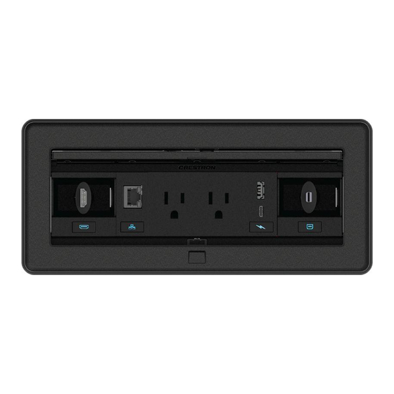
FT2-1200-ELEC Series
1200 Size, Electrical
The Crestron®
FT2-1200-ELEC
installs into a table or other horizontal surface to provide modular
tabletop connectivity. The FT2-1200-ELEC series feature a one-touch lid
that retracts fully and disappears with the tap of a button. When the lid is
retracted, 9 module slots are arranged in one row. The flexible modular
design may also be customized with an assortment of Crestron
accessories. For more information about the accessories, please visit
www.crestron.com/Crestron-FlipTops. To configure your FlipTop, launch
the
FlipTop Configuration
Tool.
The FT2-1200-ELEC Series features a built in electrical power bus, which
enables compatibility with one-touch cable retractors, active connector
plates, and USB rapid charging modules. It also enables backlighting of
the symbol icons on all retractors, connector plates, and USB charging
modules.
FlipTop™ cable management system
In the Box
1
FT2-1200-ELEC, 1200 Size, Electrical
Additional Items
3
Bars, Locking, with Screws (P/N 4528906)
1
Cable, DC Power Splitter (P/N 2050094)
1
Holder, Power Supply (P/N 2048887)
1
Power Cord, 5 ft 10 in. (1.78 m) (P/N 2042043)
1
Power Pack, 24 VDC, 2.5 A, 100-240 VAC (P/N 2045873)
1
Template, Cutout (P/N 4527491)
FT2-1200-ELEC-AL Only
1
Bezel, FT2-1200, Alloy (P/N 4528342)
FT2-1200-ELEC-B Only
1
Bezel, FT2-1200, Black (P/N 4528341)
Quick Start
1
Advertisement

Related Manuals for Crestron FT2-1200-ELEC Series


Summary of Contents for Crestron FT2-1200-ELEC Series
- Page 1 FlipTop Configuration Tool. Cable, DC Power Splitter (P/N 2050094) The FT2-1200-ELEC Series features a built in electrical power bus, which Holder, Power Supply (P/N 2048887) enables compatibility with one-touch cable retractors, active connector Power Cord, 5 ft 10 in. (1.78 m) (P/N 2042043) plates, and USB rapid charging modules.
- Page 2 Quick Start FT2-1200-ELEC Series 1200 Size, Electrical Secure the FlipTop Assembly To prepare the FT2-1200 assembly and secure it to the table surface: Mount the FlipTop Assembly 1. Locate the included DC power splitter cable. A mounting hole is required for an FT2-1200-ELEC installation. Use the included template to cut a new mounting hole for new installations.
-
Page 3: Connect The Network
Custom programming can trigger the retractors after five minutes of no video detected. Connect the FlipTop assembly to a Crestron control system or DMPS3 via the 3-pin connector using standard Cresnet cable. The red power lead is not connected and should be terminated. - Page 4 Quick Start FT2-1200-ELEC Series 1200 Size, Electrical Connect and Place the Power Supply To connect the power supply to the power bus: 1. Underneath the FT2-1200 assembly, connect the power supply to the The FT2-1200 assembly ships with one 24 VDC power supply that is used bottom of the power bus.
-
Page 5: Install The Modules
FlipTop. Installation procedures for most modules are available in separate product documentation. For more information, refer to the specific product manual located at www.crestron.com/manuals. The following sections provide best practices and installation procedures for pass-through cable modules and blank plate modules. - Page 6 Quick Start FT2-1200-ELEC Series 1200 Size, Electrical Installing the Pass-Through Cable Module with 4K 3. Attach the side plate to the module by snapping the plastic clips on the plate into the two slots on the module. Cables NOTE: If the side plate must be removed, use a small, flat object 1.
- Page 7 Quick Start FT2-1200-ELEC Series 1200 Size, Electrical 5. Insert the cable plate into one of the three slots in the pass-through 6. Attach the side plate to the module by snapping the plastic clips on the module. Choose the appropriate slot based on the length of the cable plate into the two slots on the module.
- Page 8 Quick Start FT2-1200-ELEC Series 1200 Size, Electrical Install the Locking Bars 1. Position the locking bars so that the screws attached to the locking bars engage the screw holes in the FT2-1200 assembly. 2. Using a manual torque screwdriver set to its lowest possible setting, hand tighten the locking bar screws until the locking bars are secured to the FT2-1200 assembly.
-
Page 9: Install The Bezel
Quick Start FT2-1200-ELEC Series 1200 Size, Electrical Install the Bezel Operate the FlipTop Assembly Place the bezel onto the FT2-1200 assembly so that the retractable lid fits To operate the FT2-1200 assembly: inside the bezel opening. The bezel is held in place using magnets. - Page 10 Service Providers (CSPs) under a limited nonexclusive, nontransferable Software Development Tools License Agreement. Crestron product operating system software is licensed to Crestron dealers, CSPs, and end-users under a separate End-User License Agreement. Both of these Agreements can be found on the Crestron website at www.crestron.com/legal/software_license_agreement. www.crestron.com/model/6509656 The product warranty can be found at www.crestron.com/warranty.
Need help?
Do you have a question about the FT2-1200-ELEC Series and is the answer not in the manual?
Questions and answers