
Related Manuals for Rosslare AC Series


Summary of Contents for Rosslare AC Series
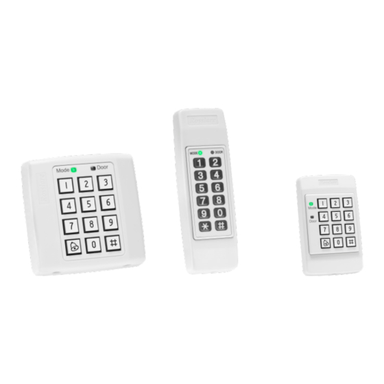
- Page 1 AC-x32 Series Standalone Access Control Units Installation and Programming Manual AC-B32 AC-C32 AC-D32...
- Page 2 ROSSLARE. ROSSLARE reserves the right to revise and change this document at any time, without being obliged to announce such revisions or changes beforehand or after the fact.
-
Page 3: Table Of Contents
Table of Contents Table of Contents Introduction ..............8 Reader/Controller Types............8 Equipment ................8 Additional Equipment .............. 9 Technical Specifications ..........10 Installation ..............12 Mounting ................12 Wiring .................. 14 3.2.1 AC-B32 ..................14 3.2.2 AC-C32 ..................15 3.2.3 AC-D32 .................. - Page 4 Table of Contents BL-D40 External Sounder ............21 Programming ............23 Entering Programming Mode ..........24 Exiting Programming Mode ........... 24 Changing Open Code 1............25 Changing Open Code 2............25 Changing the Programming Code .......... 26 Changing the Normal/Secure Code ........27 Changing the Normal/Bypass Code and Door Chime Settings ..
- Page 5 List of Figures List of Figures Figure 1: AC-B32 – Mounting Holes and Terminal Blocks ........ 12 Figure 2: AC-C32 – Mounting Holes and Terminal Blocks ........ 13 Figure 3: AC-D32 – Mounting Holes and Terminal Blocks ........ 13 Figure 4: AC-B32 – Wiring the Lock Strike Relay and REX ........ 14 Figure 5: AC-B32 –...
- Page 6 List of Tables List of Tables Table 1: Programming Menu ................23 AC-x32 Series Installation and Programming Manual...
- Page 7 ROSSLARE exclusive warranty and liability is limited to the warranty and liability statement provided in an appendix at the end of this document. ...
-
Page 8: Introduction
Introduction Introduction The AC-x32 is a series of indoor standalone controllers. The units accept up to 500 users and allow entry via a personal identification number (PIN) or by presenting a proximity card. Reader/Controller Types The six types of units described in this manual are: Keypad Type PIN Proximity AC-B32 3X4 Standard... -
Page 9: Additional Equipment
Request to Exit (REX) button – Normally Open Type; switch is closed when pressed. BL-D40 External Sounder (optional) – Provides siren, bell, and chime functions to the controller Other Rosslare accessories can be found at Rosslare's website: http://www.rosslaresecurity.com AC-x32 Series Installation and Programming Manual... -
Page 10: Technical Specifications
• Read Range: 90 mm (3.5 in.)* • Modulation: ASK at 125 kHz • Compatible cards: All 26-Bit EM cards Measured using a Rosslare proximity card or equivalent. Range also depends on electrical environment and proximity to metal. AC-x32 Series Installation and Programming Manual... - Page 11 Technical Specifications Environmental Characteristics Operating Temp. Range -31°C to 63°C (-25°F to 145°F ) Operating Humidity Range 0 to 95% (non-condensing) Physical Characteristics Dimensions AC-B32: 92 x 92 x 24 mm (3.6 x 3.6 x 0.9 in.) (Length x Width x Depth) AC-C32: 130 x 42 x 18 mm (5.1 x 1.7 x 0.7 in.) AC-D32: 122 x 75 x 24 mm...
-
Page 12: Installation
Installation Installation Installation of an RFID reader adjacent to metallic surfaces might alter the reader’s specifications. To diminish this interference, use a plastic spacer when mounting the reader. Mounting Before starting, select the location to mount the controller. This location should be at shoulder height and on the same side as the door handle. -
Page 13: Figure 2: Ac-C32 - Mounting Holes And Terminal Blocks
Installation Figure 2: AC-C32 – Mounting Holes and Terminal Blocks Figure 3: AC-D32 – Mounting Holes and Terminal Blocks 5. Wire the controller as shown in Section 3.2. 6. Screw the back plate into the surface. Ensure the screws are the size specified on the installation template. -
Page 14: Wiring
Installation Wiring Typical wiring diagrams for the various units are shown in the following subsections. 3.2.1 AC-B32 Figure 4: AC-B32 – Wiring the Lock Strike Relay and REX Figure 5: AC-B32 – Wiring the BL-D40 External Sounder AC-x32 Series Installation and Programming Manual... -
Page 15: Ac-C32
Installation 3.2.2 AC-C32 Figure 6: AC-C32 – Wiring the Lock Strike Relay and REX Figure 7: AC-C32 – Wiring the BL-D40 External Sounder AC-x32 Series Installation and Programming Manual... -
Page 16: Ac-D32
Installation 3.2.3 AC-D32 Figure 8: AC-D32 – Wiring the Lock Strike Relay and REX Figure 9: AC-D32 – Wiring the BL-D40 External Sounder AC-x32 Series Installation and Programming Manual... -
Page 17: Operation
Operation Operation User Levels The controller accepts up to 500 users and provides entry via the use of proximity cards and/or PIN codes. Each user is provided with two code memory slots: Memory Slot 1 (Primary Code) and Memory Slot 2 (Secondary Code). -
Page 18: Modes Of Operation
Operation Modes of Operation The controllers have three modes of operation: 4.2.1 Normal Mode Mode Door The Mode LED is green Green Normal Mode is the default mode. In Normal mode, the door is locked until a Primary code is presented to the controller. Special codes such as “Open Code”... -
Page 19: Changing The Modes Of Operation
Operation Changing the Modes of Operation 4.3.1 Changing from Normal to Secure Mode The default factory setting for the Normal/Secure Code is 3838. To change from Normal to Secure mode: 1. Enter the 4-digit Normal/Secure code. The Mode LED flashes red. Mode Door 2. -
Page 20: Changing From Normal To Bypass Mode
Operation 4.3.3 Changing from Normal to Bypass Mode By default, there is no Normal/Bypass code. The Normal/Bypass code must first be programmed to use this function (see Section 5.6 to create/modify the Normal/Bypass Code). To change from Normal to By pass mode: 1. -
Page 21: Case And Back Tampers
The BL-D40 External Sounder is compatible with the AC-x32 series of standalone controllers. (For a more up-to-date list of compatible products, check the Rosslare website at www.rosslaresecurity.com.) It is designed to operate indoors and is installed within the premises to be secured. - Page 22 The controller can also program the length of the siren in the BL-D40. The controller communicates with the BL-D40 using a coded proprietary Rosslare communications protocol. This provides a more secure link between the controller and the BL-D40. If the BLD40 receives any unrecognized codes on its communication line, or...
-
Page 23: Programming
Programming Programming Programming is done solely via the unit's keypad driven Programming Menu System. To reach the Programming Menu System, the unit must first be put into Programming mode (see Section 5.1). During the manufacturing process, certain codes and settings are pre- programmed. -
Page 24: Entering Programming Mode
Programming Entering Programming Mode The controller must be in Normal mode to enter the Programming mode. The factory default Programming code is 1234. If a Programming code is not entered within five seconds, the unit returns to Normal mode. To enter Programming mode: 1. -
Page 25: Changing Open Code 1
Programming Changing Open Code 1 Open Code 1 is mainly used as a method to quickly test the Lock Strike Relay during installation. The default factory setting for Open Code 1 is 2580. When the first user is added to the controller, the default Open Code 1 is automatically deleted, and is ready for a new Open Code 1 to be re-entered. -
Page 26: Changing The Programming Code
Programming To change the Open Code 2: Mode Door 1. Enter Programming mode. Green 2. Press 2 to enter Menu 2. Mode Door The Mode LED turns orange. Orange Green 3. Enter the new 4-digit Open Code 2 code. Mode Door Three beeps are emitted. -
Page 27: Changing The Normal/Secure Code
Programming Changing the Normal/Secure Code When the Auxiliary Mode is 1, 2, 3, or 4, the Auxiliary Input takes priority over the Normal/Secure Code. To change the Normal/ Secure code: Mode Door 1. Enter Programming mode. Green 2. Press 4 to enter Menu 4. The Mode LED flashes red. -
Page 28: Setting Fail Safe/Secure Operation, Tamper Siren Time, And Lock Strike Release Time
Programming 3. There are four different ways to program the Normal/Bypass code and door chime: Disable both Bypass Code and the door chime. Enter the code 0000. Disable Bypass Code and enable the door chime. Enter the code 0001. ... -
Page 29: Enrolling Primary And Secondary Codes
Programming Construct the 4-digit code using the following instructions: First Digit For Fail Secure Operation, the first digit should be 0. For Fail Safe Operation the first digit should be 1. Second Digit Siren time in minutes (1-9, 0-disabled) ... -
Page 30: Secondary Codes
Programming 5.9.2 Secondary Codes Secondary codes can only be enrolled to a user slot that already has a Primary Code enrolled, but no Secondary code. Secondary Codes do not have to be unique, meaning that multiple users can all hold the same Secondary code. ... - Page 31 Programming 3. Perform one of the following: a. Enter a 3-digit User Slot number between 001 and 500 to indicate the user to whom you want to enroll a Primary or Secondary code. For example, the User Slot 003 represents User #3. Mode Door If the selected slot has no Primary...
-
Page 32: Enrolling Secondary Codes Using The Code Search Method
Programming 5.9.5 Enrolling Secondary Codes Using the Code Search Method The Code Search feature enables you to quickly enroll a Secondary Code to a user who already has a Primary Code. To enroll secondary codes using the Code Search method: Mode Door 1. -
Page 33: Deleting Primary And Secondary Codes
Programming 5.10 Deleting Primary and Secondary Codes There are two methods to delete Primary and Secondary codes: the Standard Method and the Code Search method. When deleting a user slot, both the Primary code and the Secondary code are erased. It is recommended that a record be kept of added and deleted users so that it is easier to keep track of which user slots are empty and which user slots are not. -
Page 34: Deleting Primary And Secondary Codes Using The Code Search Method
Programming 4. Enter your 4-digit Programming code to confirm the deletion. If the Programming code is valid, three beeps are emitted and the unit returns to Normal mode. If the Programming code is invalid, a long beep is emitted and the unit returns to Normal mode. -
Page 35: Return To Factory Default Settings
Programming 4. Enter the 4-digit PIN code of the Primary Code belonging to the user you want to delete. Mode Door The Mode LED flashes red. Red Orange 5. Enter your Programming code to confirm the deletion. If the Programming code is valid, three beeps are emitted and the unit returns to Normal mode. -
Page 36: Replacing A Lost Programming Code
Programming 5.12 Replacing a Lost Programming Code To be able to replace a lost programming code, the controller must be in Normal mode. Before proceeding, verify that the Mode LED is green. 1. Remove power from the unit. 2. Press the REX button. 3. -
Page 37: Limited Warranty
The full ROSSLARE Limited Warranty Statement is available in the Quick Links section on the ROSSLARE website at www.rosslaresecurity.com. Rosslare considers any use of this product as agreement to the Warranty Terms even if you do not review them. AC-x32 Series Installation and Programming Manual... - Page 38 Tel: +86-755-8610 6842 Fax: +86-755-8610 6101 Rosslare Security Products, Inc. support.cn@rosslaresecurity.com Southlake, TX, USA India Toll Free: +1-866-632-1101 Local: +1-817-305-0006 Rosslare Electronics India Pvt Ltd. Fax: +1-817-305-0069 Tel/Fax: +91-20-40147830 support.na@rosslaresecurity.com Mobile: +91-9975768824 Europe sales.in@rosslaresecurity.com Rosslare Israel Ltd. Rosh HaAyin, Israel...
Need help?
Do you have a question about the AC Series and is the answer not in the manual?
Questions and answers