Table of Contents
Advertisement
Quick Links
P1201-M0 rev 08/07
Hand Pumps
Instruction Manual
MODELS: P1201, P1201S, P2301, P2301M & P4301
SFA Companies
10939 N. Pomona Ave. Kansas City, MO 64153
Tel: 888-332-6419
*
Fax: 816-891-6599
E-mail: sales@bvahydraulics.com
Website: www.bvahydraulics.com
!
This is the safety alert symbol. It is used to alert you to potential personal injury hazards.
Obey all safety messages that follow this symbol to avoid possible injury or death.
Maximum Operating Pressure 10,000 PSI
Models P1201 & P1201S
Models P2301 & P4301
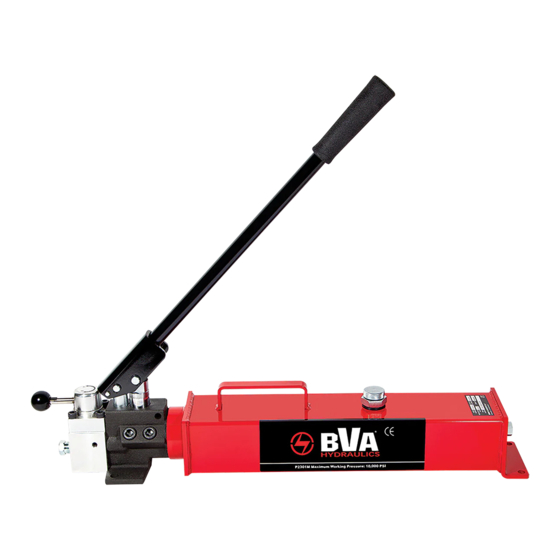
Model P2301M
Printed in Taiwan
Advertisement
Table of Contents

Subscribe to Our Youtube Channel
Related Manuals for BVA Hydraulics P1201


Summary of Contents for BVA Hydraulics P1201
- Page 1 P1201-M0 rev 08/07 Hand Pumps Instruction Manual MODELS: P1201, P1201S, P2301, P2301M & P4301 SFA Companies 10939 N. Pomona Ave. Kansas City, MO 64153 Tel: 888-332-6419 Fax: 816-891-6599 E-mail: sales@bvahydraulics.com Website: www.bvahydraulics.com This is the safety alert symbol. It is used to alert you to potential personal injury hazards.
-
Page 2: Product Description
PRODUCT DESCRIPTION BVA Hydraulic Hand Pumps are engineered to meet most industrial standards for performance and safety. Models P1201, P2301, P2301M and P4301 have a unique two- stage hydraulic circuit which allows quick displacement of hydraulic fluid under no load conditions and easy pumping in loaded conditions. -
Page 3: Specifications
Single- P1201S 0.13 3.74 22 1/4” x 5 3/8” x 6 1/2” 20.0 speed P1201 3.74 22 1/4” x 5 3/8” x 6 3/4” 20.3 10,000 P2301 3.54 24” x 5 3/8” x 6 3/4” 27.5 Two- 0.81... -
Page 4: Before Use
IMPORTANT: The pump’s maximum working pressure is 10,000 PSI. Make sure that all hydraulic equipment such as Figure 4 - Prepare to use Illustration for P1201 & P1201S cylinders, hoses, couplers and etc. used with this pump are rated at 10,000 PSI operating pressure or more. -
Page 5: Operation
OPERATION For models P1201, P1201S, P2301 & P4301: ALWAYS monitor pressure, load or position using A. Close release valve by turning it clockwise. Finger tight suitable equipment. Pressure may be monitored by means of ONLY. Using tools on release valve can damage it and an optional manifold and gauge (contact BVA Hydraulics). -
Page 6: Maintenance
MAINTENANCE 1. Inspect hoses and connections daily. Replace damaged Changing Hydraulic Fluid components immediately with BVA Hydraulics For best results, change fluid once a year. Replacement Parts only. 1. Remove vented filler plug/screw and drain used fluid into 2. Tighten connections as needed. Use pipe thread sealing a sealable container. -
Page 7: Limited Lifetime Warranty
• Damaged components, including but not limited to bent rams, dented or crushed cylinder walls, broken welds or couplers as well as worn out seals, o-rings and springs are the result of misuse and not covered by warranty and BVA Hydraulics will not provide any warranty credit for such damaged components. - Page 8 P1201-M0 convenient reference of location and position in the assembly sequence. rev 08/07 Parts Illustration (refer page 11 for part number) Note: To ensure safe and reliable performance, replace worn or damaged parts with BVA Hydraulics Authorized Replacement Parts only.
- Page 9 Parts List (Model P1201S) Item Part Number Description 677-5-0040-102 E-clip H18-5-1318-104 H18-6-1318-100 H18-6-1602-201 Pin, Piston 667-5-0100-005 C-clip H28-6-1814-100 Piston H28-6-1815-102 Piston Seat Back-up Ring U-cup O-ring H28-6-1813-108 Pump Cylinder Back-up Ring O-ring D05-6-1001-106 A17-6-1216-102 Needle Valve 512-2-0067-010 Compressing Spring A17-5-1603-300 Adjust Nut Special Washer 414-6-1215-509...
- Page 10 P1201-M0 convenient reference of location and position in the assembly sequence. rev 08/07 Parts Illustration (refer page 11 for part number) Note: To ensure safe and reliable performance, replace worn or damaged parts with BVA Hydraulics Authorized Replacement Parts only.
- Page 11 Parts List (Model P1201) Item Part Number Description 677-5-0040-102 E-clip H18-5-1318-104 H18-6-1318-100 H18-6-1602-201 667-5-0100-005 C-clip H18-3-1306-105 Piston Assy. O-ring Back-up Ring Back-up Ring O-ring D05-6-1001-106 A17-6-1216-102 Needle Valve 512-2-0082-117 Compressing Spring A17-5-1603-300 Adjust Nut Special Washer 414-6-1215-509 512-2-0067-010 Compressing Spring...
- Page 12 P1201-M0 convenient reference of location and position in the assembly sequence. rev 08/07 Parts Illustration (refer page 13 for part number) Note: To ensure safe and reliable performance, replace worn or damaged parts with BVA Hydraulics Authorized Replacement Parts only.
- Page 13 Parts List (Models P2301 & P4301) Item Part Number for Model: Description P2301 P4301 677-5-0040-102 E-clip H18-5-1318-104 H18-6-1318-100 H18-6-1602-201 667-5-0100-005 C-clip H18-3-1306-105 Piston Assy. O-ring Back-up Ring Back-up Ring O-ring D05-6-1001-106 A17-6-1216-102 Needle Valve 512-2-0082-117 Compressing Spring A17-5-1603-300 Adjust Nut Special Washer 414-6-1215-509 512-2-0067-010...
- Page 14 P1201-M0 convenient reference of location and position in the assembly sequence. rev 08/07 Parts Illustration (refer page 15 for part number) Note: To ensure safe and reliable performance, replace worn or damaged parts with BVA Hydraulics Authorized Replacement Parts only.
- Page 15 Parts List (Model P2301M) Item Part Number Description Item Part Number Description E05-6-1008-109 Knob Special Washer A67-6-1012-106 Handle Bar 414-6-1215-509 649-1-0050-055 Screw 512-2-0067-010 Compression Spring A67-6-1005-109 Control Valve Cover H28-6-1811-003 Base 601-7-0006-005 Steel Ball 651-7-0063-007 Adapter 512-2-0046-104 Compression Spring H53-6-1808-104 Tube 644-1-0060-071 Socket Bolt...
- Page 16 SFA Companies 10939 N. Pomona Ave. Kansas City, MO 64153 Tel: 888-332-6419 E-mail: sales@bvahydraulics.com...
Need help?
Do you have a question about the P1201 and is the answer not in the manual?
Questions and answers