Advertisement
Installing the Avaya WLAN Indoor Wall Access Point WAP9112
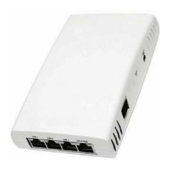
The Avaya WAP 9112 is a 2x2 802.11ac indoor wall access point (AP) with two fixed-band radios: one at 5 GHz and
one at 2.4 GHz. It includes an Ethernet wall switch with four 10/100/1000 ports, one of which may supply power.
Preparation
Run a data uplink cable (Cat5e/Cat6) for the single Gigabit uplink port.
Supply power—typically via IEEE 802.3af/at Power over Ethernet (PoE) on the same cable as the data uplink.
See Figure 2 on the next page for Uplink PoE and Pass-though ports.
The total PoE uplink cable length must be no more than 100 m, including all cable segments. The WAP must be
connected to PoE networks without routing cables to the outside plant.
If you supply 802.3at PoE power to the uplink port, you may use the WAP 9112's LAN4-PoE switch port to
supply 802.3af power and data to another device.
Alternatively, you may supply your own local 48 VDC power adapter meeting these specifications—
Output Power
Nominal Load
Current
Ripple and Noise
Connector
Polarity
Pass-through port—this simply provides an Ethernet pass-through connection (with or without POE) from the
back of the unit to a port on the side of the WAP 9112.
LAN ports—these four switch ports on the bottom of the WAP 9112 allow you to provide Ethernet connectivity
to other devices. LAN4-PoE supplies 802.3af PoE, if a 48 VDC power adapter is used
802.3at PoE power is supplied as described above.
Wall Installation
WAP 9112 Access Points (APs) should be mounted on an inside wall.
1.
Remove the blank wall plate from the wall with a screwdriver.
2.
As shown in
Figure
through the opening in the supplied mounting bracket and secure the
bracket to the wall using the two screw holes previously occupied by
the blank wall plate. Ensure that the "UP" label is at the top, and that
the tab for the locking screw is on the left facing towards you.
+48VDC
0.63A
At 20Mhz, and output parallel with 0.1uF and
10uF capacitors to ground, temperature at 25
at nominal input voltage
Jack Plug 55*2.5*11.5mm
1, feed the Uplink (PoE) and Pass-through cables
C,
°
(Step 5
below), or if
Figure 1
Locking
tab
NN47252-304 Issue 01.01
Advertisement
Table of Contents

Related Manuals for Avaya WAP9112


Summary of Contents for Avaya WAP9112
- Page 1 Installing the Avaya WLAN Indoor Wall Access Point WAP9112 The Avaya WAP 9112 is a 2x2 802.11ac indoor wall access point (AP) with two fixed-band radios: one at 5 GHz and one at 2.4 GHz. It includes an Ethernet wall switch with four 10/100/1000 ports, one of which may supply power.
- Page 2 WAP 9112 Installation Figure 2 Uplink PoE Install Pass-through Locking Screw Locking slot Locking tab Connect the cables as follows. Plug the Uplink-PoE and Pass-through cables into their respective sockets as shown in Figure 2 (A). If the cables are not fitted with RJ45 jacks, they can be connected to the punch down blocks using a dedicated network cable tool according to the sequence of colored wires marked on the back of the AP, as shown in Figure 2...
- Page 3 See the Avaya Support website: http://support.avaya.com for Product or Hosted Service documentation, notices, and articles, or to report a problem with your Avaya Product or Hosted Service. For a list of support telephone numbers and contact addresses, go to the Avaya Support website: http://support.avaya.com (or such successor site as designated by Avaya), scroll to the bottom of the page, and select Contact Avaya Support.
Need help?
Do you have a question about the WAP9112 and is the answer not in the manual?
Questions and answers