Table of Contents
Advertisement
Available languages
Available languages
Quick Links
Advertisement
Table of Contents

Related Manuals for KTM 78112964000


Summary of Contents for KTM 78112964000
- Page 1 HEATING ELEMENT 12.2018 78112964000 3.211.510 Husqvarna Motorcycles GmbH KTM Sportmotorcycle GmbH Stallhofnerstraße 3 Stallhofnerstraße 3 *3211510* A-5230 Mattighofen A-5230 Mattighofen www.husqvarna-motorcycles.com www.ktm.com...
- Page 2 3 DEUTSCH Wir freuen uns, dass Sie sich für dieses Produkt entschieden haben. Unser hochwertiges Qualitätsprodukt ist rennerprobt und wurde speziell für sportliche Herausforderungen entwickelt. Eine korrekte Montage des Produktes ist unerlässlich, um ein Maximum an Sicherheit und Funktionalität gewährleisten zu können. Bitte befolgen Sie daher die Montageanleitung oder wenden Sie sich an Ihren autorisierten Fachhändler.
-
Page 3: Montage
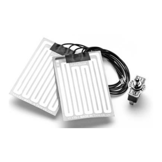
Lieferumfang: 2x Heizelement 1x Schalter 1x Kabelstrang Die Heizelemente sind nicht mit Lock-on Griffen kombinierbar! Bei Lock-on Griffen wird das Gasdrehgriffrohr 790.02.013.100, sowie ein Set Standardgriffe benötigt. Vorarbeiten - Griffgummis / Lock-on Griffe vom Lenker entfernen. - Lenker gründlich reinigen und entfetten. - Bei Modellen mit Lock-on Griffen rechts das Gasdrehgriffrohr (nicht im Lieferumfang) montieren. - Page 4 - Schließen Sie nun diese beiden Kabel (1) am mittleren Stecker (2) des Schalters an. 12 Volt Widerstand - Schließen Sie nun die beiden Kabel mit den Flachsteckhülsen (3) des mit- Leitung gelieferten Kabelstranges an den beiden äußeren Stecker (4) des Schalters Schalter HINWEIS: Zur richtigen Montage folgen Sie dem Schaltplan.
-
Page 5: Preliminary Work
Scope of delivery: 2x heating element 1x switch 1x wiring harness The heating elements cannot be combined with lock-on grips. In the case of lock-on grips, a 790.02.013.100 throttle tube and a set of standard grips are required. Preliminary work - Remove the hand grips / lock-on grips from the handlebar. -
Page 6: Final Steps
- Now connect these two cables (1) to the middle connector (2) of the switch. 12 volt Resistance - Now connect the two cables with the spade connectors (3) of the supplied line wiring harness to the two outer connectors (4) of the switch. Switch NOTE: To mount the equipment properly, adhere to the circuit diagram. - Page 7 Materiale fornito: N. 2 elementi riscaldanti N. 1 interruttore N. 1 cablaggio Gli elementi riscaldanti non sono combinabili con manopole autobloccanti! Con le manopole autobloccanti è necessario disporre del tubo della manopola dell'acceleratore 790.02.013.100, nonché di un set di mano- pole standard.
- Page 8 - Collegare quindi i due cavi (1) al connettore centrale (2) dell'interruttore. - Infine, collegare i due cavi con le spine piatte femmina (3) del fascio di Alimentazione Resistenza cavi fornito in dotazione ai due connettori esterni (4) dell'interruttore. da 12 Volt Interruttore NOTA: Per un montaggio corretto osservare lo schema elettrico.
- Page 9 Contenu de la livraison : 2x elément de réchauffage 1x bouton 1x faisceau de câbles Les éléments de réchauffage ne peuvent pas être combinés avec les poignées lock-on ! Le tube de gaz 790.02.013.100 ainsi qu’un jeu de poignées standard sont nécessaires pour les poignées lock-on.
-
Page 10: Montage Final
- Branchez maintenant les deux câbles (1) à la fiche du milieu (2) du bou- ton. 12 V Câble Résistance - Branchez maintenant les deux câbles avec les cosses Faston(3) du fais- ceau de câbles fourni aux deux connecteurs extérieurs (4) du bouton. Bouton REMARQUE : Pour un montage correct, suivez le schéma de câblage. -
Page 11: Montaje
Volumen de suministro: 2x Elemento de calefacción 1x Interruptor 1x cableado Los elementos de calefacción no pueden combinarse con puños lock-on. En caso de contar con puños lock-on se necesita la caña del puño de gas 790.02.013.100 y un juego de puños estándar. Trabajos previos - Retirar los puños de goma/puños lock-on del manillar. -
Page 12: Montaje Final
- Acto seguido, conectar estos dos cables (1) al conector central (2) del inter- ruptor. Línea de Resistencia - Finalmente, conectar los dos cables a los conectores planos (3) del mazo de 12 voltios cables suministrado y a los dos conectores exteriores (4) del interruptor. Interruptor NOTA: Para realizar el montaje correctamente, actuar de acuerdo con el esquema...
Need help?
Do you have a question about the 78112964000 and is the answer not in the manual?
Questions and answers