Table of Contents
Advertisement
Quick Links
Advertisement
Table of Contents

Subscribe to Our Youtube Channel
Related Manuals for Aerotech LaserTurn 5-ASR


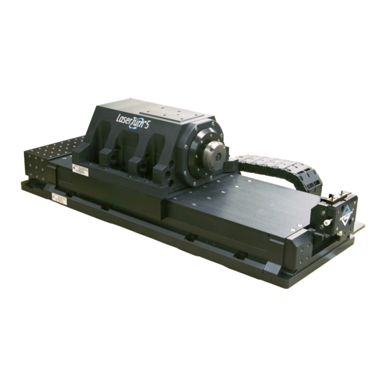
Summary of Contents for Aerotech LaserTurn 5-ASR
-
Page 1: Laserturn®5-Asr Hardware Manual
® LaserTurn 5-ASR Hardware Manual Revision: 1.04.00... - Page 2 This manual contains proprietary information and may not be reproduced, disclosed, or used in whole or in part without the express written permission of Aerotech, Inc. Product names mentioned herein are used for identification purposes only and may be trademarks of their respective companies.
-
Page 3: Table Of Contents
4.3.1. Piston Seal Change Procedure 4.3.2. Ringseal O-Ring Replacement 4.3.3. Wet Cut Rotary Union Seal Replacement 4.4. Wet Cut Rotary Union Removal 4.5. Linear Hardcover Removal 4.6. Troubleshooting Appendix A: Warranty and Field Service Appendix B: Revision History Index www.aerotech.com... -
Page 4: List Of Figures
Cross-Section View of Wet Cut Rotary Union Figure 4-6: Carriage Cover Removal Figure 4-7: Seal Assembly Removal Figure 4-8: Wet Cut Rotary Union Shaft Inspection Figure 4-9: Wet Cut Rotary Union Figure 4-10: Wet Cut Rotary Union Removal Figure 4-11: Linear Hardcover Removal www.aerotech.com... -
Page 5: List Of Tables
25-Pin Feedback Connector Pinouts (Linear Axis) Table 3-6: 25-Pin D Feedback Mating Connector Table 3-7: Feedback Specifications Table 3-8: Rotary Axis Motor Specifications (BM250) Table 3-9: Rotary Axis Motor Specifications, -WCUT (BM250) Table 3-10: Linear Axis Motor Specifications (BLM-264-A) Table 4-1: Recommended Lubricants www.aerotech.com... -
Page 6: Safety Procedures And Warnings
Read this manual in its entirety before installing, operating, or servicing this product. If you do not understand the information contained herein, contact an Aerotech representative before proceeding. Strictly adhere to the statements given in this section and other handling, use, and operational information given throughout the manual to avoid injury to you and damage to the equipment. -
Page 7: Eu Declaration Of Incorporation
® LaserTurn 5-ASR Hardware Manual Table of Contents EU Declaration of Incorporation Manufacturer: Aerotech, Inc. 101 Zeta Drive Pittsburgh, PA 15238-2811 herewith declares that the product: ® LaserTurn 5-ASR Stage is intended to be incorporated into machinery to constitute machinery covered by the Directive 2006/42/EC as amended;... - Page 8 ® Table of Contents LaserTurn 5-ASR Hardware Manual This page intentionally left blank. www.aerotech.com...
-
Page 9: Chapter 1: Overview
Overview Chapter 1: Overview N O T E : Aerotech continually improves its product offerings; listed options may be superseded at any time. All drawings and illustrations are for reference only and were complete and accurate as of this manual’s release. Refer to www.aerotech.com for the most up-to-date information. -
Page 10: Environmental Specifications
Extreme temperature changes could cause a decrease in performance or permanent damage to the stage. Aerotech stages are designed for and built in a 20°C (68°F) environment. Any deviation from standard operating temperature will affect stage accuracy. The severity of temperature effects on all stage specifications depends on many different environmental conditions, including how the stage is mounted. -
Page 11: Basic Specifications
1. Maximum speed is based on stage capability. Actual speed may be limited by system data rate, resolution, or amplifier selection. 2. Maximum loads are mutually exclusive. Loading limits are due to the collet chuck mechanism. Contact Aerotech directly if part load requirement exceeds specifications. - Page 12 ® Overview LaserTurn 5-ASR Hardware Manual This page intentionally left blank. Chapter 1 www.aerotech.com...
-
Page 13: Chapter 2: Installation
Allowing it to stabilize to room temperature will ensure that all of the alignments, preloads, and tolerances are the same as they were when tested at Aerotech. Use compressed nitrogen or clean, dry, oil- less air to remove any dust or debris that has collected during shipping. -
Page 14: Figure 2-1: Laserturn®5-Asr Shipping Clamps
® Installation LaserTurn 5-ASR Hardware Manual ® Figure 2-1: LaserTurn 5-ASR Shipping Clamps ® Figure 2-2: LaserTurn 5-ASR Lifting Points Chapter 2 www.aerotech.com... -
Page 15: Dimensions
Installation 2.2. Dimensions N O T E : Aerotech continually improves its product offerings; listed options may be superseded at any time. All drawings and illustrations are for reference only and were complete and accurate as of this manual’s release. Refer to www.aerotech.com for the most up-to-date information. -
Page 16: Figure 2-4: Laserturn®5-Asr Dimensions (Part Two)
® Installation LaserTurn 5-ASR Hardware Manual ® Figure 2-4: LaserTurn 5-ASR Dimensions (part two) Chapter 2 www.aerotech.com... -
Page 17: Securing The Stage To The Mounting Surface
W A R N I N G : Do not attempt to move the carriage (or table top) of the LaserTurn 5-ASR until the lifting and shipping brackets have been removed. Moving the carriage with the lifting and ® shipping brackets installed can cause permanent damage to the LaserTurn 5-ASR. www.aerotech.com Chapter 2... -
Page 18: Figure 2-5: Laserturn®5-Asr Stage Showing Mounting Holes (Top View)
® Installation LaserTurn 5-ASR Hardware Manual ® Figure 2-5: LaserTurn 5-ASR Stage Showing Mounting Holes (Top View) Figure 2-6: Tooling Platform Hardware Chapter 2 www.aerotech.com... -
Page 19: Air Requirements
Water or cutting fluid must be filtered to 5 microns or better. A fluid filter must be installed upstream of the rotary union between the pump outlet and the rotary union inlet. www.aerotech.com Chapter 2... -
Page 20: Attaching The Payload To The Stage
Once air is supplied, material of the appropriate size can be placed in the collet. All collets supplied by Aerotech are clearly labeled with their clamping size range and collet style. Be sure to use only the correct size material in the collet. If an incorrect material size is clamped, the accuracy of the collet could be compromised. -
Page 21: Load Capability
To prevent damage or performance degradation of the stage, the unsupported length and weight of the attached pressure vessel is limited. N O T E : Aerotech recommends the following limitations on the size and weight of an unsupported pressure vessel: Length past end of rotary union (L): <250 mm... -
Page 22: Changing The Workholding Devices
5-ASR stages may be equipped with ER16 style collets. It is important that only the collets designed for a particular collet holder are used. Contact the factory for more details. N O T E : Aerotech recommends using only electro-polished collets manufactured to DIN6499 specifications. -
Page 23: Figure 2-8: Inserting The Collet Into The Collet Nut
® LaserTurn 5-ASR Hardware Manual Installation Figure 2-8: Inserting the Collet into the Collet Nut www.aerotech.com Chapter 2... -
Page 24: Figure 2-9: Installing The Collet And Collet Nut
® Installation LaserTurn 5-ASR Hardware Manual Figure 2-9: Installing the Collet and Collet Nut Chapter 2 www.aerotech.com... -
Page 25: Gripper Installation (-Ft2)
N O T E : Do not exceed 87 psi to the gripper on the open or closing cycle. N O T E : Refer to the pneumatics layout drawing included with the documentation for assembly instructions. www.aerotech.com Chapter 2... -
Page 26: Alignment Gripper Installation (-Ft3 And -Ft6)
N O T E : Do not exceed 87 psi to the gripper on the open or closing cycle. N O T E : Refer to the pneumatics layout drawing included with the documentation for assembly instructions. Chapter 2 www.aerotech.com... -
Page 27: Figure 2-11: Alignment Gripper
® LaserTurn 5-ASR Hardware Manual Installation Figure 2-11: Alignment Gripper www.aerotech.com Chapter 2... -
Page 28: Gripper Jaw Interface
® Installation LaserTurn 5-ASR Hardware Manual 2.11. Gripper Jaw Interface Figure 2-12 shows the dimensions of the gripper jaw interface without the gripper jaws. Figure 2-12: Gripper Jaw Interface Dimensions Chapter 2 www.aerotech.com... -
Page 29: Chapter 3: Electrical Specifications And Installation
5-ASR Hardware Manual Electrical Specifications and Installation Chapter 3: Electrical Specifications and Installation W A R N I N G : Electrical installation must be performed by properly qualified personnel. Aerotech motion control systems are adjusted at the factory for optimum performance. When the ® LaserTurn 5-ASR is part of a complete Aerotech motion control system, setup usually involves connecting ®... -
Page 30: Motor And Feedback Connectors
N O T E : Refer to the other documentation accompanying your Aerotech equipment. Call your Aerotech representative if there are any questions on system configuration. N O T E : If using standard Aerotech motors and cables, motor and encoder connection adjustments are not required. -
Page 31: Table 3-1: 4-Pin Hpd Motor Connector Pinouts (For Rotary And Linear Axes)
Motor Phase C Reserved Reserved Reserved Reserved Reserved Frame ground (motor protective ground) Table 3-2: 4-Pin D Motor Mating Connector Mating Connector Aerotech P/N Third Party P/N Backshell ECK00656 Amphenol #17E-1726-2 Sockets [QTY. 4] ECK00659 ITT Cannon #DM53744-6 Connector ECK00657 ITT Cannon #DBM9W4SA197 www.aerotech.com... -
Page 32: Table 3-3: 25-Pin D Feedback Connector Pinouts (Rotary Axis)
Common ground (internally connected to Pin 20) Reserved Reserved Reserved Reserved Case Signal shield connection (to case) Table 3-4: 25-Pin D Feedback Mating Connector Mating Connector Aerotech P/N Third Party P/N Backshell ECK00656 Amphenol #17E-1726-2 Connector ECK00300 FCI DB25S064TLF Chapter 3 www.aerotech.com... -
Page 33: Table 3-5: 25-Pin Feedback Connector Pinouts (Linear Axis)
Reserved Signal indicating maximum travel produced by negative/CCW stage direction Reserved Case Signal shield connection (to case) Table 3-6: 25-Pin D Feedback Mating Connector Mating Connector Aerotech P/N Third Party P/N Backshell ECK00656 Amphenol #17E-1726-2 Connector ECK00300 FCI DB25S064TLF www.aerotech.com... -
Page 34: Motor And Feedback Wiring
All motor and controller manufacturers have their own designations for motor phases A/B/C and Hall signals A/B/C (refer to Section 3.5. for motor phasing). Shielded cables are required for the motor and feedback connections. Figure 3-1: Motor and Feedback Wiring (Rotary Axis) Chapter 3 www.aerotech.com... -
Page 35: Figure 3-2: Motor And Feedback Wiring (Linear Axis)
® LaserTurn 5-ASR Hardware Manual Electrical Specifications and Installation Figure 3-2: Motor and Feedback Wiring (Linear Axis) www.aerotech.com Chapter 3... -
Page 36: Motor And Feedback Specifications
Requires external pull-up to +5 V (10 kΩ recommended) Notes: ® If the LaserTurn 5-ASR is driven beyond the electrical limit, it will encounter a mechanical stop. Impacting the mechanical stop could cause damage to the stage even at low speeds. Chapter 3 www.aerotech.com... -
Page 37: Table 3-8: Rotary Axis Motor Specifications (Bm250)
5. Torque constant and motor constant specified at stall 6. Maximum winding temperature is 130 °C 7. Ambient operating temperature range 0 °C - 25 °C; consult Aerotech for performance in elevated ambient temperatures 8. All Aerotech amplifiers are rated A ;... -
Page 38: Table 3-9: Rotary Axis Motor Specifications, -Wcut (Bm250)
5. Torque constant and motor constant specified at stall 6. Maximum winding temperature is 130 °C 7. Ambient operating temperature range 0 °C - 25 °C; consult Aerotech for performance in elevated ambient temperatures 8. All Aerotech amplifiers are rated A ;... -
Page 39: Table 3-10: Linear Axis Motor Specifications (Blm-264-A)
5. All performance and electrical specifications ±10% 6. Maximum winding temperature is 125°C. 7. Ambient operating temperature range 0 °C - 25 °C; consult Aerotech for performance in elevated ambient temperatures 8. All Aerotech amplifiers are rated Apk; use force constant in N·m/Apk when sizing. -
Page 40: Limits, Marker, And Machine Direction
5-ASR Hardware Manual 3.4. Limits, Marker, and Machine Direction Aerotech stages are configured to have positive and negative "machine" directions. The machine direction defines the phasing of the feedback and motor signals and is dictated by the stage wiring (refer to Section 3.5. -
Page 41: Motor And Feedback Phasing
® LaserTurn 5-ASR Hardware Manual Electrical Specifications and Installation 3.5. Motor and Feedback Phasing Motor phase voltage is measured relative to the virtual wye common point. Figure 3-4: Hall Phasing www.aerotech.com Chapter 3... -
Page 42: Figure 3-5: Analog Encoder Phasing Reference Diagram
® Electrical Specifications and Installation LaserTurn 5-ASR Hardware Manual Figure 3-5: Analog Encoder Phasing Reference Diagram Chapter 3 www.aerotech.com... -
Page 43: Chapter 4: Maintenance
(whichever comes first). For stages operating under conditions involving excessive debris, the stage should be cleaned every six months. For high-speed applications (those near max speed at a duty cycle of 50%), frequent maintenance with standard lubricants is required. www.aerotech.com Chapter 4... -
Page 44: Cleaning And Lubrication
For more information about how to clean and lubricate the linear bearings, refer to Section 4.2.2. Linear Lubrication and Cleaning Process. For more information about how to lubricate the wet cut rotary union seals, refer to Section 4.3.3. Wet Cut Rotary Union Seal Replacement. Chapter 4 www.aerotech.com... -
Page 45: Collet & Collet Chuck Lubrication And Cleaning
If the wear marks are large, or excessive polishing is required to remove these marks, the collet chuck and collet may need to be replaced. Contact Aerotech Technical Support for more information. Wear and fretting can be prevented with proper lubrication and maintenance intervals. -
Page 46: Linear Lubrication And Cleaning Process
Step 8: Repeat steps 3 through 7 for any areas covered by the original table position. Step 9: Refasten the hardcover. Step 10: Restore power to the stage and drive the stage table back to its original position to redistribute lubricants. Figure 4-1: Linear Bearing Grease Nipple Chapter 4 www.aerotech.com... -
Page 47: Seal Replacement
4.3.2. Ringseal O-Ring Replacement During the lifetime of the stage, it may be necessary to change the ringseal o-rings. Contact Aerotech to obtain proper replacement seals. Depending on the size, the ringseal may be one or two pieces. The ringseal screws into the center of the shaft from the front of the stage. -
Page 48: Figure 4-3: Typical Ringseal
4-4). A long pick or thin screwdriver will be necessary to remove the o-ring and replace it. Contact Aerotech for the appropriate o-ring size and type. Step 6: Wrap the ringseal threads with Teflon thread sealing tape [PTFE tape] in preparation for installation. -
Page 49: Wet Cut Rotary Union Seal Replacement
5-ASR Hardware Manual Maintenance 4.3.3. Wet Cut Rotary Union Seal Replacement The rotary seal in the wet cut rotary union requires periodic replacement. Contact Aerotech for obtaining appropriate replacement seals. Figure 4-5 shows a cross section of the rotary union assembly. -
Page 50: Figure 4-6: Carriage Cover Removal
Step 2: Remove the six seal assembly screws from the rear end of the rotary union (see Figure 4-6). Figure 4-7: Seal Assembly Removal Step 3: Carefully pull the seal assembly off of the stage. 4.3.3 shows an exploded view of the seal assembly. Chapter 4 www.aerotech.com... - Page 51 If the shaft and seal retainer sealing surface are undamaged, clean both the shaft and seal assembly surfaces with a lint-free cloth and isopropyl alcohol. If the shaft or sealing surface is scratched (you can feel it with your fingernail), contact Aerotech customer service.
-
Page 52: Figure 4-8: Wet Cut Rotary Union Shaft Inspection
Step 9: Press the seal assembly back over the rotary union shaft. Use care so that damage does not occur to the newly installed seal. Step 10: Tighten the seal assembly screws and reattach the cover and fitting. Step 11: Restore power to the stage. Chapter 4 www.aerotech.com... -
Page 53: Wet Cut Rotary Union Removal
Step 2: Remove the rear carriage cover and top carriage cover that is on the backside of the carriage. See Section 4.3.3. for the removal procedure. Step 3: Remove the shoulder bolts and bushings (see Figure 4-10). www.aerotech.com Chapter 4... -
Page 54: Figure 4-10: Wet Cut Rotary Union Removal
Step 5: Install a new rotary union assembly by attaching it to the rear of the LaserTurn 5-ASR shaft. Tighten to 13.5 N·m [10 ft-lbs]. Tighten the shoulder bolts and bushings. Step 6: Reattach all covers. Step 7: Restore power to the stage. Chapter 4 www.aerotech.com... -
Page 55: Linear Hardcover Removal
Step 3: Remove [QTY-8] M4 flat head socket screws from the center of the cover. Step 4: Remove [QTY-4] M5 flat head socket screws from the cover near the front endplate. Step 5: Lift the hardcover straight up to remove it. Step 6: Repeat these steps to remove the rear hardcover. www.aerotech.com Chapter 4... -
Page 56: Troubleshooting
Insufficient air pressure supplied to the stage. Make sure there are no blockages in the supply line and the pressure is high enough (refer to Section 2.4.). The collet has not been lubricated properly or the lubrication needs to be replenished (refer to Section 4.2.1.). Chapter 4 www.aerotech.com... -
Page 57: Appendix A: Warranty And Field Service
Aerotech makes no warranty that its products are fit for the use or purpose to which they may be put by the buyer, whether or not such use or purpose has been disclosed to Aerotech in specifications or drawings previously or subsequently provided, or whether or not Aerotech’s... - Page 58 Aerotech's approval. On-site Warranty Repair If an Aerotech product cannot be made functional by telephone assistance or by sending and having the customer install replacement parts, and cannot be returned to the Aerotech service center for repair, and if Aerotech determines the problem could be warranty-related, then the following policy applies:...
-
Page 59: Appendix B: Revision History
Section 1.3. Added pressure vessel limitations: Section 2.7. Changes for wet cut rotary union seal replacement: Section 4.3.3. Added wet cut rotary union removal section: Section 4.4. Changed page numbering from section based to absolute 1.00.00 New manual www.aerotech.com Appendix B... - Page 60 ® Revision History LaserTurn 5-ASR Hardware Manual This page intentionally left blank. Appendix B www.aerotech.com...
-
Page 61: Index
(air) cleaning Limit Switch Specifications collet/collet chuck linear linear cleaning mounting surface lubrication solvents spar cover removal Cleaning linear motion guide Collet Type lubrication collet/collet chuck linear tooling platforms cleaning load capability lubrication rotary union compressed air www.aerotech.com Index... - Page 62 Straightness Pitch Support pressure vessel length/weight limits Protection Rating Technical Support temperature and accuracy Repeatability Thermistor Specifications requirements Travel ringseal o-ring replacement Vibration rotary Rotary Motor Specifications 37-39 Warranty and Field Service Wet Cut Fluid Requirements Index www.aerotech.com...
- Page 63 ® LaserTurn 5-ASR Hardware Manual Index wet cut rotary union removal wet cut rotary union seal replacement www.aerotech.com Index...
- Page 64 ® Index LaserTurn 5-ASR Hardware Manual This page intentionally left blank. Index www.aerotech.com...
Need help?
Do you have a question about the LaserTurn 5-ASR and is the answer not in the manual?
Questions and answers