Table of Contents
Advertisement
Quick Links
Advertisement
Table of Contents

Related Manuals for Fermax DUOX CITYLINE Series


Summary of Contents for Fermax DUOX CITYLINE Series
- Page 1 DUOX SYSTEM TECHNICAL BOOK SECTION I...
- Page 2 DUOX technical book - Section I Code 970122I-1 V02_18 This technical document has been edited by FERMAX ELECTRÓNICA S.A.U. for informational purposes, and the company reserves the right to modify any of the technical specifi cations of the products referred to herein at any time without prior notice.
- Page 3 INDEX 1. INTRODUCTION 1.1 DUOX: EASE OF INSTALLATION 1.2 COMPONENTS OF A DUOX SYSTEM 1.2.1 OUTDOOR PANEL 1.2.2 AUDIO GUARD UNIT 1.2.3 POWER SUPPLY SET 1.2.4 LINE ADAPTER 1.2.5 REGENERATORS 1.2.6 APARTMENT TERMINALS: MONITORS AND TELEPHONES 1.3 PRINCIPAL TECHNICAL SPECIFICATIONS OF THE DUOX SYSTEM 1.4 OPERATING PRINCIPLES OF THE DUOX SYSTEM 1.5 RECEIVING CALLS 1.5.1 MAKING CALLS BASED ON THE CONFIGURATION OF THE OUTDOOR PANEL...
- Page 4 4. POWER SUPPLY SET: POWER SUPPLY + DUOX FILTER 5. DUOX LINE ADAPTER 5.1 DEVICES WHICH INCLUDE A LINE ADAPTER 5.2. WHERE TO INSTALL A LINE ADAPTER AND HOW TO CONFIGURE IT 6. DUOX REGENERATOR 6.1 DUOX 1S REGENERATOR (REF. 3256) 6.2 DUOX 2S REGENERATOR (REF.
- Page 5 9. DUOX INSTALLATIONS 9.1 PRIOR CONSIDERATIONS REGARDING WIRING AND DUOX CONSUMPTION 9.2 BASIC VIDEO INSTALLATIONS (Monitors) AND MIXED INSTALLATIONS (Monitors + Telephones) 9.2.1 EXAMPLE OF A DUOX BASIC INSTALLATION. 1 RISER 9.2.2 EXAMPLE OF A DUOX BASIC INSTALLATION. 2 RISERS 9.2.3 EXAMPLE OF A DUOX BASIC INSTALLATION.
- Page 6 1. INTRODUCTION DUOX is the fi rst completely digital video door communication system to be based on 2 non-polarised wires. These specifi cations make it an extremely versatile and scalable system which is highly recommended in both new-build and replacement facilities. In the latter case, the DUOX system has a wide range of scope for application as a result of its fl...
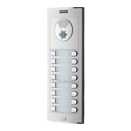
- Page 7 1.2.1 OUTDOOR PANEL These are available in all of the FERMAX styles: Cityline, Skyline and Marine. Depending on their function (the way in which they make the call) and the intrinsic specifi cations of the model, the outdoor panels may be: Pushbutton, Direct or Digital.
- Page 8 1.2.3 POWER SUPPLY SET The power supply cannot be connected directly to the Power supply set bus, given the DUOX system features, as the power supply and the data travel along the same wires. The power supplies must always be accompanied by the DUOX fi...
- Page 9 1.3 PRINCIPAL TECHNICAL SPECIFICATIONS OF THE DUOX SYSTEM • A simplifi ed installation system in two non-polar wires, which require neither fl oor distributors nor outdoor panel switchers. This leads to a considerable reduction in installation time. • The signal transmission (audio, video and data) is completely digital, allowing it to maximise its capacity and robustness to noise and interference.
- Page 10 • Auto-start. The apartment terminals can be auto-started with the outdoor panel as long as the system is not busy. The monitors have a specifi c button for this function, whereas in the case of telephones, auto-start takes place when the headset is picked up or when audio communication is established (headset-free model: hands-free).
- Page 11 Pushbutton outdoor panels: In the pushbutton panels, each pushbutton corresponds to a specifi c “call code/call direction”. This means that the call to the apartment is placed by pressing the corresponding call button. Keypad panels (Direct): The call to the apartment is placed by entering the “call code/ call direction”...
- Page 12 It is also possible to establish communication with the outdoor panel without a previous call using the auto switch-on function which is available in audio and video terminals, (see section 7. Apartment Terminals). During the communication interval, it is possible to release the door using the pushbutton that has been enabled for this purpose in the apartment terminal.
- Page 13 • Outdoor panel confi gured as General Entrance General Entrance, telephone range BBSSNN (000001 to 999999). Example: Making a call from an outdoor panel in the General Entrance to Apartment 2 Block 4. When placing the call, the code to enter is: The call code generated by the outdoor panel: Notes: - If a code with an unexpectedly short length is entered, this is fi...
- Page 20 The amplifi er manages all of the functions of an installation (calling, communication in both directions, door release, programming and so on). These are available in all of the FERMAX styles: Cityline, Skyline and Marine. Depending on their function (the way in which they make the call) and the intrinsic specifi cations of the model, the outdoor panels may be: Pushbuttons, Direct or Digital.
- Page 21 2.1.1 VIDEO AMPLIFIER FOR CITYLINE AND MARINE OUTDOOR PANELS WITH PUSHBUTTONS a) SETTINGS CN9: TAMPER connection 1a) Outdoor panel settings JP1: Camera LEDs LEDS ON. switched on when the camera is activated. LEDS OFF. always switched off. JP2: Line adapter Integrated in the amplifi...
- Page 22 5a) Technical specifi cations of the amplifi er Power supply 18 Vdc Standby consumption 165mA Maximum active audio consumption 480mA Audio power in the apartment-outdoor panel direction Audio power in the outdoor panel-apartment direction 0.15 W Operating temperature [-25º , +55ºC] / [-13º, 131ºF] Volume adjustable in both directions Video Resolution...
- Page 23 Note: Voice-assisted confi guration is for all of the outdoor panels with PUSHBUTTONS regardless of the aesthetic design: VERSION ALIMENTACION POWER SUPPLY FERMAX ELECTRONICA, SAU AV TRES CRUCES, 133 18 Vdc - Cityline outdoor panels 46017 VALENCIA - SPAIN - Marine outdoor panels - Skyline outdoor panels 1.
- Page 24 18Vdc + GND VERSION ALIMENTACION POWER SUPPLY FERMAX ELECTRONICA, SAU AV TRES CRUCES, 133 18 Vdc 46017 VALENCIA - SPAIN Pre-wiring for Marine kit panels with 1 and 2 pushbuttons with 8-pushbutton call extension module All of the Marine outdoor panels require the installation of the call extension module, regardless of the number of pushbuttons.
- Page 25 16 CALL EXTENSION PACK EXIT 18Vdc + GND 5 6 7 9 10 14 15 VERSION ALIMENTACION POWER SUPPLY FERMAX ELECTRONICA, SAU AV TRES CRUCES, 133 18 Vdc 46017 VALENCIA - SPAIN ARRIBA ARRIBA ARRIBA ARRIBA ARRIBA ARRIBA Connection of several call extension modules (more than 16 pushbuttons)
- Page 26 ADAPTOR REF. 2008 EXIT 18Vdc + GND VERSION ALIMENTACION POWER SUPPLY FERMAX ELECTRONICA, SAU AV TRES CRUCES, 133 18 Vdc 46017 VALENCIA - SPAIN ARRIBA ARRIBA ARRIBA Connection of several call extension modules (more than 8 pushbuttons) PREVIOUS - CN1...
- Page 27 5 6 7 9 10 14 15 VERSION ALIMENTACION POWER SUPPLY FERMAX ELECTRONICA, SAU AV TRES CRUCES, 133 18 Vdc 46017 VALENCIA - SPAIN Connection of several call extension modules (more than 16 pushbuttons) PACK EXTENSION 16 LLAMADAS PACK EXTENSION 16 LLAMADAS REF.2441...
- Page 28 EXIT REF. 2008 18Vdc + GND VERSION ALIMENTACION POWER SUPPLY FERMAX ELECTRONICA, SAU AV TRES CRUCES, 133 18 Vdc 46017 VALENCIA - SPAIN Connection of several call extension modules (more than 8 pushbuttons) NEXT - CN2 PREVIOUS - CN1 PREVIOUS - CN1 REF.
- Page 29 2.1.2 VIDEO AMPLIFIER FOR SKYLINE, DIRECT AND DIGITAL OUTDOOR PANELS a) SETTINGS 1a) Outdoor panel settings CN9: TAMPER connection JP1: Camera LEDs LEDS ON. switched on when the camera is activated. LEDS OFF. always switched off. JP2: Line adapter Integrated in the amplifi er for potential use. SW1 button CN1 (6 pins) Connection of modular pushbuttons, keypad and display.
- Page 30 3a) Outdoor panel coding* Whenever there is more than one outdoor panel, it will be necessary to program the number of outdoor panels. 4a) Camera focus / Lock release activation time* This adjusts the camera image or adjusts the door opening time. *Note: Consult the relevant sub-section for the type of panel in question: - Pushbutton panel: 2b) Voice-assisted confi...
- Page 31 b) CONFIGURATION The DUOX amplifi er includes “Restore” and “Change Value” functions which enable users to restore/ change the parameters that have been programmed. SKYLINE PUSHBUTTON PANEL 1b) Reset of the mapping of the call code of the pushbuttons 2b) Voice-assisted confi guration in pushbutton panels Note: See chapter 2.1.1 VIDEO AMPLIFIER FOR CITYLINE AND MARINE PANELS WITH PUSHBUTTONS, sub-section b) CONFIGURATION.
-
Page 32: Enter Programming Mode
Confi guration of parameters Enter the two digits from the position, a “beep” will sound, then enter the chosen value (1, 2, 3 or 4 digits depending on the parameter). If the value is correct, a confi rmation tone will sound (beep- beep) and the new value will be saved. -
Page 33: Access Control
2. CONFIGURATION: This enables the setting of the parameters of the outdoor panel. Use the numeric keypad to select the desired confi guration option. 2. CONFIGURATION 1. SYSTEM 2. CODES 1. DOOR OPENING TIME Lock release activation time. 3. ACCESS CONTROL Activation of the lock release 4. - Page 34 LANGUAGE SW1 PROG LEDS LINE ADAPTOR EXIT 18Vdc + GND CT VERSION ALIMENTACION POWER SUPPLY FERMAX ELECTRONICA, SAU AV TRES CRUCES, 133 18 Vdc 46017 VALENCIA - SPAIN INPUT MÓDULO PULSADOR PUSH-BUTTON MODULE MODULE BOUTON-POUSSOIR TASTEMODUL OUTPUT INPUT MÓDULO PULSADOR...
- Page 35 LANGUAGE SW1 PROG LEDS LINE ADAPTOR EXIT 18Vdc + GND CT VERSION ALIMENTACION POWER SUPPLY FERMAX ELECTRONICA, SAU AV TRES CRUCES, 133 18 Vdc 46017 VALENCIA - SPAIN INPUT MÓDULO PULSADOR PUSH-BUTTON MODULE MODULE BOUTON-POUSSOIR TASTEMODUL OUTPUT INPUT MÓDULO PULSADOR...
- Page 36 Nº LANGUAGE SW1 PROG LEDS LINE ADAPTOR EXIT 18Vdc + GND CT VERSION ALIMENTACION POWER SUPPLY FERMAX ELECTRONICA, SAU AV TRES CRUCES, 133 18 Vdc 46017 VALENCIA - SPAIN ENTRADA/INPUT ARRIVÉE/EINTRITT MÓDULO TECLADO KEYPAD MODULE MODULE CLAVIER TASTATURMODUL SALIDA/OUTPUT SORTIE/AUSGANG...
- Page 37 Nº LANGUAGE SW1 PROG LEDS LINE ADAPTOR EXIT 18Vdc + GND CT VERSION ALIMENTACION POWER SUPPLY FERMAX ELECTRONICA, SAU AV TRES CRUCES, 133 18 Vdc 46017 VALENCIA - SPAIN ENTRADA/INPUT ARRIVÉE/EINTRITT MÓDULO TECLADO KEYPAD MODULE MODULE CLAVIER TASTATURMODUL SALIDA/OUTPUT SORTIE/AUSGANG...
- Page 38 Nº LANGUAGE SW1 PROG LEDS LINE ADAPTOR EXIT 18Vdc + GND CT VERSION ALIMENTACION POWER SUPPLY FERMAX ELECTRONICA, SAU AV TRES CRUCES, 133 18 Vdc 46017 VALENCIA - SPAIN ENTRADA/INPUT ARRIVÉE/EINTRITT MÓDULO TECLADO KEYPAD MODULE MODULE CLAVIER TASTATURMODUL SALIDA/OUTPUT SORTIE/AUSGANG...
- Page 39 2.1.3 AUDIO AMPLIFIER FOR CITYLINE AND MARINE OUTDOOR PANELS WITH PUSHBUTTONS a) SETTINGS 1a) Outdoor panel settings CN9: TAMPER connection SW1 button DL2: Status Led Intermittent slow blinking. Inverse or Sequential Programming (mapping). Shut down. Standby CN1 (5 pins) Connection of the call extension module. Language selection 1 of the “door open”...
- Page 40 5a) Technical specifi cations of the amplifi er Power supply 18 Vdc Standby consumption 94mA Active audio consumption 550 mA Audio power in the apartment-outdoor panel direction Audio power in the outdoor panel-apartment direction 0,15 W Operating temperature [-10º , +60ºC] / [-14º, 140ºF] Volume adjustable in both directions 6a) Outdoor panel amplifi...
- Page 41 EXIT 18Vdc Note: Voice-assisted confi guration is for all of the outdoor panels with PUSHBUTTONS regardless of the aesthetic design: VERSION FERMAX ELECTRONICA, SAU AV TRES CRUCES, 133 46017 VALENCIA - SPAIN - Cityline outdoor panels - Marine outdoor panels - Skyline outdoor panels 1.
- Page 42 CN9 TAMPER EXIT 18Vdc VERSION FERMAX ELECTRONICA, SAU AV TRES CRUCES, 133 46017 VALENCIA - SPAIN Pre-wiring for Marine kit panels with 1 and 2 pushbuttons with 8-pushbutton call extension module All of the Marine outdoor panels require the installation of the call extension module, regardless of the number of pushbuttons.
- Page 43 CN9 TAMPER REF.2441 16 CALL EXTENSION PACK EXIT 18Vdc 5 6 7 9 10 14 15 VERSION FERMAX ELECTRONICA, SAU AV TRES CRUCES, 133 46017 VALENCIA - SPAIN ARRIBA ARRIBA ARRIBA ARRIBA ARRIBA ARRIBA Connection of several call extension modules (more than 16 pushbuttons)
- Page 44 IDIOMA LANGUAGE SW1 PROG CN9 TAMPER REF. 2008 EXIT 18Vdc VERSION FERMAX ELECTRONICA, SAU AV TRES CRUCES, 133 46017 VALENCIA - SPAIN ARRIBA ARRIBA ARRIBA Connection of several call extension modules (more than 8 pushbuttons) PREVIOUS - CN1 NEXT - CN2 PREVIOUS - CN1 REF.
- Page 45 EXIT 18Vdc 5 6 7 9 10 14 15 VERSION FERMAX ELECTRONICA, SAU AV TRES CRUCES, 133 46017 VALENCIA - SPAIN Connection of several call extension modules (more than 16 pushbuttons) PACK EXTENSION 16 LLAMADAS PACK EXTENSION 16 LLAMADAS REF.2441 16 EXTENSION CALL PACK REF.2441...
- Page 46 LANGUAGE SW1 PROG CN9 TAMPER REF. 2008 EXIT 18Vdc VERSION FERMAX ELECTRONICA, SAU AV TRES CRUCES, 133 46017 VALENCIA - SPAIN Connection of several call extension modules (more than 8 pushbuttons) PREVIOUS - CN1 NEXT - CN2 PREVIOUS - CN1 REF.
- Page 47 2.1.4 AUDIO AMPLIFIER FOR SKYLINE, DIRECT AND DIGITAL OUTDOOR PANELS. a) SETTINGS 1a) Outdoor panel settings CN9: TAMPER connection SW1 button DL2: Status Led Intermittent slow blinking. Inverse or Sequential Programming (mapping of pushbutton panels). Shut down. Standby. CN1 (6 pins) Connection of modular pushbuttons, keypad and display.
- Page 48 3a) Outdoor panel coding* Whenever there is more than one outdoor panel, it will be necessary to program the number of outdoor panels. 4a ) Lock release activation time* Adjusts the door opening time. *Note: Consult the relevant sub-section for the type of panel in question: - Pushbutton panel: 2b) Voice-assisted confi...
- Page 49 b) CONFIGURATION The DUOX amplifi er includes “Restore” and “Change Value” functions which enable users to restore/ change the parameters that have been programmed. SKYLINE PUSHBUTTON PANEL 1b) Reset of the mapping of the call code of the pushbuttons 2b) Voice-assisted confi guration in pushbutton panels Note: See chapter 2.1.3 AUDIO AMPLIFIER FOR CITYLINE AND MARINE PANELS WITH PUSHBUTTONS, sub-section b) CONFIGURATION.
-
Page 50: Enter Programming Mode
Confi guration of parameters Enter the two digits from the position, a “beep” will sound, then enter the chosen value (1, 2, 3 or 4 digits depending on the parameter). If the value is correct, a confi rmation tone will sound (beep- beep) and the new value will be saved. - Page 51 2. CONFIGURATION: This enables the setting of the parameters of the outdoor panel. Use the numeric keypad to select the desired confi guration option. 2. CONFIGURATION 1. SYSTEM 2. CODES 1. DOOR OPENING TIME Lock release activation time. 3. ACCESS CONTROL Activation of the lock release 4.
- Page 52 See detail. TYPE Nº Nº IDIOMA LANGUAGE SW1 PROG CN9 TAMPER EXIT 18Vdc VERSION FERMAX ELECTRONICA, SAU AV TRES CRUCES, 133 46017 VALENCIA - SPAIN INPUT MÓDULO PULSADOR PUSH-BUTTON MODULE MODULE BOUTON-POUSSOIR TASTEMODUL OUTPUT INPUT MÓDULO PULSADOR...
- Page 53 SKYLINE MOD./ OUT TYPE Nº Nº IDIOMA LANGUAGE SW1 PROG CN9 TAMPER EXIT 18Vdc VERSION FERMAX ELECTRONICA, SAU AV TRES CRUCES, 133 46017 VALENCIA - SPAIN INPUT MÓDULO PULSADOR PUSH-BUTTON MODULE MODULE BOUTON-POUSSOIR TASTEMODUL OUTPUT INPUT MÓDULO PULSADOR PUSH-BUTTON MODULE...
- Page 54 SKYLINE MOD./ OUT TYPE Nº Nº IDIOMA LANGUAGE SW1 PROG CN9 TAMPER EXIT 18Vdc VERSION FERMAX ELECTRONICA, SAU AV TRES CRUCES, 133 46017 VALENCIA - SPAIN ENTRADA/INPUT ARRIVÉE/EINTRITT MÓDULO TECLADO KEYPAD MODULE MODULE CLAVIER TASTATURMODUL SALIDA/OUTPUT SORTIE/AUSGANG Pre-wiring for DIGITAL Skyline outdoor panel...
- Page 55 SKYLINE MOD./ OUT TYPE Nº Nº IDIOMA LANGUAGE SW1 PROG CN9 TAMPER EXIT 18Vdc VERSION FERMAX ELECTRONICA, SAU AV TRES CRUCES, 133 46017 VALENCIA - SPAIN ENTRADA/INPUT ARRIVÉE/EINTRITT MÓDULO TECLADO KEYPAD MODULE MODULE CLAVIER TASTATURMODUL SALIDA/OUTPUT SORTIE/AUSGANG Pre-wiring for DIGITAL City outdoor panel...
- Page 56 SKYLINE MOD./ OUT TYPE Nº Nº IDIOMA LANGUAGE SW1 PROG CN9 TAMPER EXIT 18Vdc VERSION FERMAX ELECTRONICA, SAU AV TRES CRUCES, 133 46017 VALENCIA - SPAIN ENTRADA/INPUT ARRIVÉE/EINTRITT MÓDULO TECLADO KEYPAD MODULE MODULE CLAVIER TASTATURMODUL SALIDA/OUTPUT SORTIE/AUSGANG Pre-wiring for DIGITAL Marine outdoor panel...
- Page 57 2.2 ADVANCED PROGRAMMING 2.2.1 MAPPING IN PUSHBUTTON PANELS The call code generated by a pushbutton of a pushbutton panel is determined by: - Integrated pushbuttons in the “amplifi er” of Cityline 1- or 2-line outdoor panels. - The connection to the “call extension module”: in Cityline outdoor panels with more than 2 pushbuttons and •...
- Page 58 VIDEO Amplifi er INVERSE PROGRAMMING. 2 operators are required. This mode enables the assignment of non-consecutive call codes (addresses). The steps to be taken are as follows: 1. The outdoor panel should fi rst be confi gured as the master outdoor panel (see note on previous page). 2.
-
Page 59: Sequential Programming
SEQUENTIAL PROGRAMMING. Only 1 operator is required. This mode enables the sequential assignment of call codes (directions) in the order desired. The steps to be taken are as follows: 1. The outdoor panel should fi rst be confi gured as the master outdoor panel (see note on previous page). 2. - Page 60 AUDIO Amplifi er INVERSE PROGRAMMING. 2 operators are required. This mode enables the assignment of non-consecutive call codes (addresses). The steps to be taken are as follows: 1. The outdoor panel should fi rst be confi gured as the master outdoor panel (see note on previous page). 2.
- Page 61 SEQUENTIAL PROGRAMMING. Only 1 operator is required. This mode enables the sequential assignment of call codes (directions) in the order desired. The steps to be taken are as follows: 1. The outdoor panel should fi rst be confi gured as the master outdoor panel (see note on previous page). 2.
- Page 62 Mapping can be effectuated from the outdoor panel (keypad + display) or using the extra display software. The Display Plus software is a PC-based application which serves to exchange data with the FERMAX EXTRA DISPLAY unit. This exchange of data makes it possible to perform different operations with the display, meaning that...
-
Page 63: Add Users
b) ENABLE ALPHANUMERIC KEYPAD (in order to be able to write user names) 3. DISPLAY: Enables the performance of settings relating to information from the display. Use the numeric keypad to select the desired confi guration option. 3. SETTINGS. 3. DISPLAY T h i s o p t i o n e n a b l e s t h e 1. - Page 64 d) ENABLE MAPPED CALLING 2. CONFIGURATION: This enables the setting of the parameters of the outdoor panels. Use the numeric keypad to select the desired confi guration option. 4. CALLING. This option makes it possible to configure the manner in 2.
- Page 65 3. DUOX AUDIO GUARD UNIT The DUOX system can be complemented with one or more GUARD UNITS (in the general entrance and/or in internal blocks) which can be wall-mounted or desk-mounted. The central unit of the guard unit acts as a “fi lter” between residents of a building and visitors.
-
Page 66: Operation
2. OPERATION 12.06.2016 10:58 2.1 SCREENS AND ICONS COMMUNICATION Communication Date Hour Unit MISSED CALLS 01/02 17:10 010003 01/02 11:25 010002 01/02 09:37 020001 08:45 040008 01/02 Open door OPEN DOOR North South East West Call volume CALL VOLUME PARAMETERS Settings SETTINGS (ADMINISTRATOR MENU) -
Page 67: Led Signalling
2.2 LED SIGNALLING The guard unit includes an LED: Switched on: Guard unit with power supply in standby mode (screen shut down). Shut down: Guard unit with screen switched on or without power supply. Blinking: Missed calls. 3. CONNECTION TERMINALS, TECHNICAL SPECIFICATIONS AND DEFAULT VALUES B B A +12V B +12V... - Page 68 4. POWER SUPPLY SET: POWER SUPPLY + DUOX FILTER The DUOX system has a power supply with a voltage of 18Vdc. The power supply that should be used is: Ref. 4830 Power supply 18Vdc/3.5A. The power supply cannot be connected directly to the bus, given the DUOX System features, as the power supply and the data travel along the same wires.
- Page 69 5. DUOX LINE ADAPTER With the DUOX system it is necessary to adapt the transmission line. Line adapter ref. 3255 can be used for this purpose. DUOX LINE ADAPTOR There are also other devices that include a line adapter in their structure. REF: 3255 This adapter balances impedances in the transmission line.
-
Page 70: Video Amplifier
VIDEO AMPLIFIER Line adapter integrated to the output bus, with confi gurable adaptation (“C” or “no adaptation”) using jumper JP2. The default confi guration is “no adaptation” (OFF). Note: DUOX audio amplifi ers do not have an integrated line adapter. VEO MONITOR: Includes a JP1 jumper: Line adaptation bridge, which enables confi... - Page 71 5.2.WHERE TO INSTALL A LINE ADAPTER AND HOW TO CONFIGURE IT VIDEO INSTALLATIONS Generally speaking, when working with video installations we can state that adapters are always installed at the beginning and at the end of the riser, but the place in which the adapters should be situated will depend slight on the number of risers and on whether the installation is in cascade format or whether it involves several terminals per derivation point.
- Page 72 One riser More than one riser ref. 3255 ref. 3255 ref. 3255 ref. 3255 ref. 3255 PREV BUS 18 Vdc IN PREV BUS 18 Vdc IN DUOX POWER DUOX POWER SUPPLY ADAPTER MODULE SUPPLY ADAPTER MODULE MADE IN SPAIN MADE IN SPAIN REF.
- Page 73 AUDIO-ONLY INSTALLATIONS Generally speaking, when dealing with audio installations we can state that the adapters are always installed at the end of the riser. a) In cascade installations: - One riser: place a line adapter at the last terminal. - More than one riser: place a line adapter at the last terminal of each riser. - All adapters are confi...
- Page 74 One riser More than one riser ref. 3255 ref. 3255 ref. 3255 18 Vdc IN PREV BUS 18 Vdc IN PREV BUS DUOX POWER DUOX POWER SUPPLY ADAPTER MODULE MADE IN SPAIN SUPPLY ADAPTER MODULE MADE IN SPAIN REF. 3244 REF.
- Page 75 6. DUOX REGENERATOR This element is capable of completely regenerating the DUOX signal. As it works in both directions, it does this both in the input-output direction and in the output-input direction. As well as regenerating the signal, it also electrically isolates the sections of the installation to which it is connected. The main function and purpose of a regenerator is to increase distances, risers and terminals in an installation.
- Page 76 The INPUT/OUTPUT terminals can be connected interchangeably in an installation (regeneration happens in both directions). However, only the INPUT terminal has an incorporated line adapter (confi gurable using JP1), which means that the orientation of the regenerator should be determined by the installer, in order to benefi...
- Page 77 B B: BUS INPUT connector DUOX Bus TERM A MADE IN SPAIN TERM C REF. 3256 TERM OUTPUT B B: BUS OUTPUT connector Regenerator DUOX 1S DUOX 1W REGENERATOR DUOX Bus JP1: Integrated line adapter (to the input: BUS INPUT connector) •...
- Page 78 Diagram ref. 3255 ref. 3255 ref. 3255 ref. 3255 ref. 3255 ref. 3255 PWR DATA PWR DATA SW1: DOWNLINK POWER OUTPUT regenerator B1 B2 DERIVADOR TRONCALES DUOX 18 Vdc DUOX RISERS SPLITTER REF: 3253 SW1 OFF SW1 ON TERM C TERM A NO TERM INPUT...
- Page 79 Regenerator DUOX 2S DUOX 2W REGENERATOR REF: 3253 12 5 Connectors +18V, - : 18 Vdc input power supply B B: Terminals connecting the bus of the input riser. B B: Duplicate terminals connecting the bus of the input riser Facilitates connectivity in parallel.
- Page 80 Technical Characteristics: Power supply 18 Vdc Consumption 130 mA Operating temperature [-5º , +40ºC] / [23º, 104ºF] Dimensions DIN 10: 175 (H) x 90 (V) x 60 (P) mm Minimum data signal (without rippling) 1 Vp The maximum direct current load during the start is 1 A. 6.3 DUOX 1S MULTI-CHANNEL REGENERATOR (REF.
- Page 81 Diagram 1...
- Page 82 6.4 COMPARISON BETWEEN REGENERATORS The main differences that can be noted between the different regenerators are: - Size and format. - Inputs / Outputs. - Power supply. - Primary use. Regenerator Regenerator Multi-channel regenerator Device 1 Output 2 Outputs 1 Output Specifi...
- Page 83 7.1 VEO XS MONITOR CONTROL BUTTONS / LEDS Digital menu for settings and confi guration of internal parameters. (If the monitor has been programmed). In conversation, push to open the door. In stand-by mode, call to the concierge (if applicable). Auxiliary function (check with your installer).
-
Page 84: Monitor Programming
Cascade Distribution: 2 monitors per fl oor +A F1 +A F1 +A F1 +A F1 Distribution: 4 monitors per fl oor +A F1 +A F1 +A F1 +A F1 MONITOR PROGRAMMING Notes: - Before programming the monitor, the outdoor panel should be set as the master outdoor panel. - Confi... -
Page 85: Audio Settings
PROGRAMMINGFROM THE MONITOR (only one person is required to complete the programming process) Select the icon and confi rm with PROGRAMMING MENU Each time that is pressed, the number increases (starting from 1) and Nº: the arrow is used for scrolling. ENTER NUMBER The white cursor indicates the entry position of the digit. -
Page 86: Time And Date Settings
This feature is deactivated by default in all monitors, although can be activated at your own responsibility. Furthermore, the legislation may force to place a sign next to door stations, indicating that monitors can capture images. You can download it at https://www.fermax.com/intl/en/corporate/utilities.html. Push to activate/... - Page 87 7.2 VEO MONITOR CONTROL BUTTONS / LEDS Digital menu for settings and confi guration of internal parameters. (If the monitor has been programmed). In conversation, push to open the door. In stand-by mode, call to the concierge (if applicable). Auxiliary function (check with your installer). In standby mode, press and the screen will display the possibility of performing auto switch-on with different outdoor panels.
- Page 88 Cascade Distribution: 2 monitors per fl oor +A F1 +A F1 +A F1 +A F1 Distribution: 4 monitors per fl oor +A F1 +A F1 +A F1 +A F1 MONITOR PROGRAMMING Notes: - Before programming the monitor, the outdoor panel should be set as the master outdoor panel. - Confi...
- Page 89 PROGRAMMINGFROM THE MONITOR (only one person is required to complete the programming process) Select the icon and confi rm with PROGRAMMING MENU Each time that is pressed, the number increases (starting from 1) and Nº: the arrow is used for scrolling. ENTER NUMBER The white cursor indicates the entry position of the digit.
-
Page 90: Date And Time Settings
This feature is deactivated by default in all monitors, although can be activated at your own responsibility. Furthermore, the legislation may force to place a sign next to door stations, indicating that monitors can capture images. You can download it at https://www.fermax.com/intl/en/corporate/utilities.html. Push to activate/... - Page 91 7.3 LOFT BASIC PLUS TELEPHONE CONTROL BUTTONS Lock release button / Call to the concierge: · While in conversation with the outdoor panel, pushing this button will activate the lock release. · With the telephone hanging up (in standby mode), pressing this button will make a call to the concierge (if applicable).
-
Page 92: Telephone Programming
TELEPHONE PROGRAMMING Notes: - Before programming the telephone, the outdoor panel should be set as the master outdoor panel. - Confi guration as master outdoor panel. Press button SW1 3 times in quick succession. Once 2 seconds have elapsed, a confi rmation tone will sound and the master outdoor panel will be activated. Once the programming of the monitors is complete, it is advisable to deactivate the MASTER outdoor panel by pressing button SW1 3 consecutive times. - Page 93 1. Selection of call ring tone for outdoor panel: With the telephone hung up and on standby mode, press the programming button of the telephone (a “beep” will sound) and without releasing this button, press the lock release button. The current melody will be heard. Release the programming button. Each time the lock release button is pressed again, the next melody will sound.
- Page 94 Cascade Distribution. 2 telephones per fl oor B B T B B T B B T B B T Distribution. 4 telephones per fl oor B B T B B T B B T B B T TELEPHONE PROGRAMMING Notes: - Before programming the telephone, the outdoor panel should be set as the master outdoor panel.
- Page 95 1. With the telephone connected and hung up, press the programming button until a “beep” sounds. On releasing the programming button, the “enter programming mode” will sound (long beep). As an additional option, the telephone handset can be picked up to establish communication with the outdoor panel and inform the operator of which apartment it is found in.
- Page 96 7.5 iLOFT TELEPHONE CONTROL BUTTONS / LEDS Lock release button / Call to the concierge: · While in conversation with the outdoor panel (audio activated), pushing this button will activate the lock release. - On receiving the call (non-active audio). If audio communication is not established, there are 30 seconds in which to complete the release process.
- Page 97 Cascade Distribution. 2 telephones per fl oor +A F1 +A F1 +A F1 +A F1 Distribution. 4 telephones per fl oor +A F1 +A F1 +A F1 +A F1 TELEPHONE PROGRAMMING Notes: - Before programming the telephone, the outdoor panel should be set as the master outdoor panel. - Confi...
- Page 98 BEEP press call to apartment button ¸ 5" enter apartment call code < 2.5 minutes 2. Press the F1 button and the 3. Press the call code/button from the outdoor button simultaneously for 5” until panel to the apartment. A confi rmation tone a “BEEP”...
- Page 99 TECHNICAL SPECIFICATIONS Power supply 18 Vdc Standby consumption + LED 18 mA Maximum consumption 210 mA Maximum conversation time 90 seconds 6-digit address 000001...999999 Operating temperature [-5º , +40ºC] / [23º, 104ºF] Dimensions 146 x 90 x 20mm (Height x Width x Depth) Choice of call melodies Number of conversation channels (audio-only installation): 2 per bus Conversation modes...
- Page 100 The relay has several confi gurable operating modes: 1- RX Mode. The relay activates its output when it receives the confi gured programmed command. The usual functions normally include: - Activation of the relay when effectuating the release. - Activation of the relay when generating a call from the outdoor panel to the apartment. - Activation of the relay when a call to the concierge is received.
- Page 101 9. DUOX INSTALLATIONS 9.1 PRIOR CONSIDERATIONS REGARDING WIRING AND DUOX CONSUMPTION DUOX is characterised by its level of fl exibility in terms of the use of different cable types. In replacement works, it functions with existing wiring from previous door entry and video door entry installations. Some of the cables supported by DUOX include: •...
- Page 102 9.2 BASIC VIDEO INSTALLATIONS (Monitors) AND MIXED INSTALLATIONS (Monitors + Telephones) The term “Basic DUOX Installation” makes reference to installations that can be set up without regenerators. It is characterised by: • Including the following devices: - Outdoor panel - Power supply set - Monitors and Telephones.
- Page 103 9.2.2 EXAMPLE OF A DUOX BASIC INSTALLATION. 2 RISERS TABLE: Maximum distance from the outdoor panel to the fi rst fork: CASCADE 2 Terminals x Storey 4 Terminals x Storey 6 Terminals x Storey 2 Risers 30 metres 30 metres 30 metres ref.
- Page 104 9.2.4 EXAMPLE OF A DUOX BASIC INSTALLATION. 4 RISERS TABLE: Maximum distance from the outdoor panel to the fi rst fork: CASCADE 2 Terminals x Storey 4 Terminals x Storey 6 Terminals x Storey 4 Risers 15 metres ref. 3255 PREV BUS 18 Vdc IN DUOX POWER...
-
Page 105: Extended Installation
ref. 3255 ref. 3255 ref. 3255 ref. 3255 18 Vdc IN PREV BUS DUOX POWER MADE IN SPAIN SUPPLY ADAPTER MODULE REF. 3244 18 Vdc INPUT Ref. 3244 18Vdc/2A OUTPUT 18Vdc/2A PWR BUS PWR BUS 9.4 EXTENDED INSTALLATION An “Extended Installation” refers to any installation that exceeds the technical specifi cations indicated in a Basic Installation. - Page 106 Example 1: Regenerator WITHOUT a power supply set in the outdoor panel to the storeys (apartments) PWR DATA PWR DATA SW1: DOWNLINK POWER OUTPUT B1 B2 regenerator DERIVADOR TRONCALES DUOX DUOX RISERS SPLITTER 18 Vdc REF: 3253 SW1 OFF SW1 ON TERM C TERM A NO TERM...
- Page 107 - Dividing an extended installation into several basic installations. See Example. Extended Installation Building Building General Entrance TERM A TERM A TERM C MADE IN SPAIN TERM C MADE IN SPAIN TERM OUTPUT REF. 3256 TERM OUTPUT REF. 3256 REGENERADOR DUOX 1S REGENERADOR DUOX 1S 1W DUOX REGENERATOR 1W DUOX REGENERATOR...
- Page 108 Avd. Tres Cruces, 133 46017 Valencia Spain...
Need help?
Do you have a question about the DUOX CITYLINE Series and is the answer not in the manual?
Questions and answers