Table of Contents
Advertisement
SERIAL RANGE: 19274001 - ________
PRODUCT MANUAL
Model Numbers & Serial Numbers
Manuals
Country Clipper Operators Manual
Country Clipper Parts Manual
Kawasaki Engine Owner Manuals
Kohler Engine Owner Manuals
Warranty
Country Clipper Warranty
Kawasaki Engine Warranty
Kohler Engine Warranty
Hydro-Gear Warranty
Battery Warranty
Additional Information
Country Clipper Product Specifications
Notes/Service Records
P-13434 (04/20)
Advertisement
Table of Contents

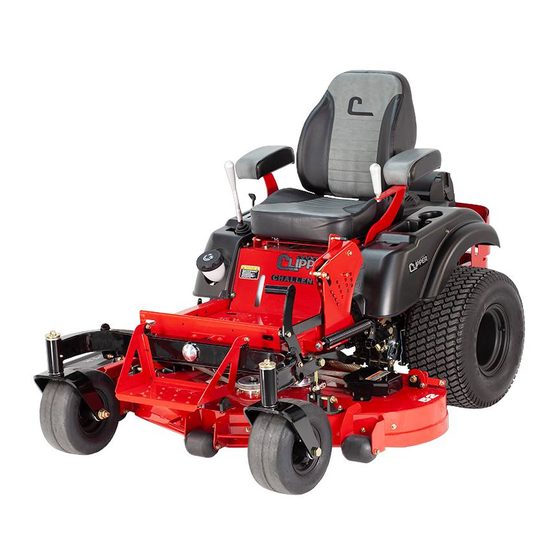
Related Manuals for Country Clipper Challenger D505


Summary of Contents for Country Clipper Challenger D505
- Page 1 SERIAL RANGE: 19274001 - ________ PRODUCT MANUAL Model Numbers & Serial Numbers Manuals Country Clipper Operators Manual Country Clipper Parts Manual Kawasaki Engine Owner Manuals Kohler Engine Owner Manuals Warranty Country Clipper Warranty Kawasaki Engine Warranty Kohler Engine Warranty Hydro-Gear Warranty...
- Page 2 SERIAL RANGE: 19274001 - ________ Congratulations for buying a Country Clipper product. Your Country Clipper Zero Turn Radius Riding Mower was designed and built to provide long and trouble free service. Keep in mind that it, like any other mechanical device, can...
-
Page 3: Table Of Contents
Country Clipper Safety Instructions and Operation TABLE OF CONTENTS SAFETY ............................ 3 ACCIDENT PATTERNS TO AVOID ......................3 SAFETY INSTRUCTIONS AND RECOMMENDATIONS ..............3 SAFETY INTERLOCK SYSTEM ......................4 START UP AND OPERATION ....................5 CHECKLIST BEFORE OPERATION ...................... 5 CONTROL LOCATIONS JOYSTICK MODELS ................... -
Page 4: Safety
CONTACT WITH THE ROTATING BLADE -- This BEGINNING OPERATORS SHOULD LEARN HOW accident usually happens when the operator is clearing TO STEER the Country Clipper Zero Turn Radius the discharge chute of grass, (especially when the Mower before attempting to mow. Start with slow... -
Page 5: Safety Interlock System
SAFETY INTERLOCK SYSTEM 19. KEEP ALL NUTS, BOLTS, AND SCREWS TIGHT to be sure equipment is in safe working condition, Your Country Clipper Zero Turn Radius Mower is especially blade mounting bolts. equipped with switches interlocked for your safety. 20. MOWER SHOULD BE STOPPED AND INSPECTED... -
Page 6: Start Up And Operation
Country Clipper Safety Instructions and Operation START UP AND OPERATION CONTROL LOCATIONS CHECKLIST BEFORE OPERATION JOYSTICK MODELS 1. Make sure fuel tank is full. Use regular unleaded Choke Blade Clutch Switch gasoline (see engine owner’s manual for more details). WARNING HANDLE GASOLINE WITH CARE -- IT IS HIGHLY FLAMMABLE. -
Page 7: Operation Joystick Models
CAUTION IMPORTANT: AVOID HILLS AND SLOPES. USE EXTREME Until the operator is familiar with the Country Clipper CAUTION WHEN MOWING UP OR DOWN SLOPES. Zero Turn Radius Mower, he/she should follow these NEVER MOW ACROSS THE FACE OF A SLOPE. IF recommendations: 1) Disengage the mower blades. -
Page 8: Control Locations Twinstick Models
Ignition 8. RELEASE PARKING BRAKE. Push brake lever down to release. IMPORTANT: Twinstick Control Until the operator is familiar with the Country Clipper Throttle Lever (RH) Zero Turn Radius Mower, he/she should follow these recommendations: 1) Disengage the mower blades. -
Page 9: Operation Free Wheel
Country Clipper Safety Instructions and Operation 10. BRAKING: To brake mower, gently move the OPERATION Twinstick Control Levers in the direction opposite to FREE WHEEL travel. NOTE: If the parking brake is engaged with 1. TO FREE WHEEL: the Twinstick Control Lever(s) in the “IN” position the engine will stop. -
Page 10: Mowing Recommendations
Country Clipper Safety Instructions and Operation CAUTION MOWER TRANSPORT NEVER OPERATE MOWER WITHOUT DISCHARGE RECOMMENDATIONS CHUTE IN PLACE. 1. SECURING THE DECK IN TRANSPORT MOWING RECOMMENDATIONS POSITION: A. Move the Transport Latch Release Handle 1. Keep mower blades sharp. forward to the LOCK position. -
Page 11: Maintenance
Country Clipper Safety Instructions and Operation MAINTENANCE CAUTION BEFORE PERFORMING ANY MAINTENANCE, TURN OFF ENGINE REMOVE KEY AND DISCONNECT SPARK PLUGS. USE EXTREME CARE WHEN WORKING ON MACHINERY. DO NOT WEAR WATCHES OR JEWELRY. DO NOT WEAR LOOSE FITTING CLOTHES, AND OBSERVE ALL COMMON SAFETY PRACTICES WITH TOOLS. -
Page 12: Maintenance Instructions
CAUTION engine operating and maintenance instructions furnished by the engine manufacturer and included STOP ENGINE, REMOVE IGNITION KEY AND in your Country Clipper Zero Turn Radius Mower SPARK PLUGS FOR SAFETY. information packet. A. Remove bolt and blade washer mounting NOTE: Air intake screen must be kept clean. - Page 13 Country Clipper Safety Instructions and Operation D. While holding the Joystick Control Lever firmly in the 7. PARKING BRAKE ADJUSTMENT: full speed forward position shorten the linkage to the A. Move Parking Brake Lever to the “OFF” right side transmission by rotating the coupling nut position.
- Page 14 Country Clipper Safety Instructions and Operation SETTING NEUTRAL: JOYSTICK CONTROL LEVER SENSITIVITY ADJUSTMENT: If, with the Joystick Control Lever in the DOWN To change the sideways turning response, adjust as (“Neutral”) or start position and the engine follows: running the mower moves or travels, it is A.
-
Page 15: Setting The Forward Tracking
Country Clipper Safety Instructions and Operation TWINSTICK ADJUSTMENT SETTING THE OPERATOR HANDLES: A. There are three positional adjustments for the 1. SETTING NEUTRAL: operator hands. The length or height of the A. Each twin lever control is linked directly to the handles has two available positions. -
Page 16: Hydrostatic Transmission
Country Clipper Safety Instructions and Operation C. Open the by-pass valve (Set to “Free Wheel”). Stop the machine and shut off the engine. See pg.10 On the wheel that needs adjusted, turn the D. Remove the oil filter (Drains Fluid). -
Page 17: Procedure For Raising And Lowering The Deck For Servicing
Country Clipper Safety Instructions and Operation D. Flip up front step (if equipped). PROCEDURE FOR RAISING AND E. Release the deck belt tension by carefully LOWERING THE DECK FOR SERVICING rotating the Deck Belt Tension Lever on the 1. RAISING THE DECK TO THE SERVICING deck. - Page 18 Country Clipper Safety Instructions and Operation MOWER SHOWN IN OPERATING POSITION. Joystick Control Lever Grease Zerk Deck Belt Tension Lever Front Step Cut Height Foot Pedal Deck Lift Handle MOWER SHOWN IN SERVICING POSITION. Cut Height Foot Pedal Flip up...
-
Page 19: Leveling The Deck
4. Measure from the ground to the front blade tip of each outside blade. These measurements should be within 1/8” of each other. (NOTE: To simplify this measuring, an optional Blade Measuring Tool, part number 629-374A is available from your local “Country Clipper dealer). Front Deck Height... -
Page 20: Trouble Shooting Check List
Country Clipper Safety Instructions and Operation TROUBLE SHOOTING CHECK LIST ENGINE WON’T TURN OVER: Mower blades engaged --------------------------------------------------------------------------------- disengage blades Drive not in neutral -------------------------------------------------------- move Control Lever(s) to neutral position Blown fuse --------------------------------------------------------------------------------------------------------- replace fuse Dead battery ----------------------------------------------------------------------------------------------- charge or replace... -
Page 21: Trouble Shooting Check List Con't
Country Clipper Safety Instructions and Operation TROUBLE SHOOTING CHECK LIST CON’T 11. TRANSMISSION LOSES POWER OR TRANSMISSIONS OVER HEATS: Transmission damage -----------------------------------------------------------------------------------------consult dealer 12. MOWER TRANSMISSION DOES NOT ENGAGE RIGHT AND/OR LEFT HAND: Transmission Free Wheel engaged--------------------------------------------------------------disengage Free Wheel Loose or damage Control Linkage --------------------------------------------------------------------------consult dealer Low Transmission oil -------------------------------------------------------------------------------------------consult dealer 13. - Page 22 Repair Parts SERIAL RANGE: 19274001 - ________ P-13434...
- Page 23 WIRE HARNESS & RELATED PARTS – JOYSTICK WIRE HARNESS & RELATED PARTS – TWIN LEVER WIRE HARNESS SCHEMATIC – JOYSTICK WIRE HARNESS SCHEMATIC – TWIN LEVER Country Clipper Division Shivvers Manufacturing Inc. 613 W English St. Corydon, IA 50060-0467 Ph. 641-872-2544 Fax. 641-872-1593 P-13434...
- Page 24 Country Clipper Repair Parts 48" DECK ASSEMBLY {722F-002A} SPINDLE ASS’Y FIXED IDLER (SEE PG 5) ASS’Y, FRONT (SEE PG 8) BELT TENSION DOUBLE IDLER ASS’Y LEVER (SEE PG 6) (SEE PG 7) FIXED IDLER ASS’Y, REAR (SEE PG 8) CHUTE ASS’Y...
- Page 25 Country Clipper Repair Parts 52" DECK ASSEMBLY {722E-002A} BELT TENSION FIXED IDLER DOUBLE IDLER ASS’Y LEVER ASS’Y, FRONT (SEE PG 6) (SEE PG 7) (SEE PG 8) SPINDLE ASS’Y (SEE PG 5) FIXED IDLER ASS’Y, REAR (SEE PG 8) CHUTE ASS’Y...
- Page 26 Country Clipper Repair Parts 60" DECK ASSEMBLY {722D-002A} SPINDLE ASS’Y DOUBLE IDLER ASS’Y (SEE PG 5) BELT TENSION (SEE PG 6) FIXED IDLER LEVER ASS’Y, FRONT (SEE PG 7) (SEE PG 8) FIXED IDLER ASS’Y, REAR (SEE PG 8) CHUTE ASS’Y...
- Page 27 Country Clipper Repair Parts DISCHARGE CHUTE ASS’Y & RELATED PARTS PART OF ITEM #2 ITEM # PART # DESCRIPTION 643-110P CHUTE HINGE 643-135A OUTLET STIFFENER W/DECALS, SMALL F-1009-02 WASHER, FLAT F-2063 NUT, 5/16-18, NYLOC, FLANGED, YZ F-2066 BOLT, CARRIAGE, 5/16-18 X 1", YZ, GR5 F-2148 FHCS, 5/16-18 X 1", YZ, GR5...
- Page 28 Country Clipper Repair Parts DECK SPINDLE ASSEMBLY {D-4020} TORQUE TO 75 FT/LBS USE ITEM #4 - 60" DECK BLADE PART NUMBERS #5 - 48" DECK #6 - 52" DECK 48" DECK H-2882 HIGH LIFT W/O FUSION (STANDARD) H-2659 LOW LIFT H-2665 GATOR 52"...
- Page 29 Country Clipper Repair Parts DOUBLE IDLER DRIVE BELT IDLER DECK BELT TENSION LEVER (SEE PG 7) ITEM # PART # DESCRIPTION 620-201P WASHER, BEARING CAP 660-039P MOUNT, DOUBLE IDLER 660-081P EXTENSION, SPRING 660-107P BELT KEEPER, A BELT 668-021P SPACER, BELT GUARD 714-183P BELT GUARD, 54’’...
- Page 30 Country Clipper Repair Parts BELT TENSION LEVER ORIENTATION FOR 52" DECK USE ITEM #1 - 48" DECK #5 - 52" DECK #6 - 60" DECK ITEM # PART # DESCRIPTION 660-031P BELT TIGHTENER ARM 660-038P SPACER, 3/8" WIDE 660-184P HANDLE, BELT TENSIONER...
- Page 31 Country Clipper Repair Parts FIXED IDLER ASSEMBLIES REAR FRONT USE ITEM #2 - 48" & 52" DECKS #3 - 60" DECKS DECK DECK DECK ITEM # PART # DESCRIPTION 620-201P WASHER, BEARING CAP 660-112P BELT KEEPER 660-114P BELT KEEPER, SINGLE END...
- Page 32 Country Clipper Repair Parts DECK LIFT ASSEMBLY & RELATED PARTS ONLY PARTIALLY TIGHTEN UNTIL COMPLETE ASS’Y 17 9 IS INSTALLED (PAGES 9-11) ITEM # PART # DESCRIPTION ITEM # PART # DESCRIPTION 720-010P CLAMP EXTENSION F-1966 NUT, THIN, 1/2-13, NYLOC, YZ...
- Page 33 Country Clipper Repair Parts DECK LIFT ASSEMBLY & RELATED PARTS (CON’T) TIGHTEN BOLT AND FIRST NUT TO WELDMENT, THEN INSTALL SPRING, WASHER, AND SECOND NUT (DO NOT OVERTIGHTEN) FULLY TIGHTEN THEN BACK OFF 1/2 TO 1 TURN 720-099A (ITEM #4)
- Page 34 Country Clipper Repair Parts CUT HEIGHT ASSEMBLY & RELATED PARTS CUT HEIGHT SUB-ASSEMBLY (SEE DETAIL) INSIDE VIEW OF CUT HEIGHT SUB-ASSEMBLY, SHOWING DECALS 18 12 HOOK SPRING (WITH HOOK ON TOP) IN BOTTOM HOLE - 48" DECK TOP HOLE - 52" & 60" DECKS...
- Page 35 Country Clipper Repair Parts PIVOTING FRONT AXLE & FLOOR PAN TORQUE TO 250 FT/LBS GREASE GREASE TORQUE TO 25 FT/LBS MAX ENSURE AXLE MOVES FREELY ITEM # PART # DESCRIPTION 606-303P WASHER, 10GA GALVANIZED 720-052W WLDT, PIVOT SHAFT 720-077W WLDT, FRONT AXLE...
- Page 36 Country Clipper Repair Parts TIRES & FRONT STEP TORQUE TO 75 FT/LBS TORQUE TO 75 FT/LBS USE ITEM #13 - 52" & 60" DECKS #14 - 48" DECKS GREASE ITEM # PART # DESCRIPTION 659-092P WHEEL BACKING PLATE 663-134P STEP, EXTENDED...
- Page 37 Country Clipper Repair Parts FRONT PANEL ASS’Y & RELATED PARTS TWIN LEVER MODELS ONLY USE ITEM #4 - XLT JOYSTICK #5 - XLT TWIN LEVER #7 - CHALLENGER JOYSTICK #8 - CHALLENGER TWIN LEVER TWIN LEVER MODELS ONLY USE ITEM...
- Page 38 Country Clipper Repair Parts FRONT PANEL ASS’Y ROUTE WIRE HARNESS & RELATED PARTS (CON’T) E-6600 (JOYSTICK) E-6649 (TWIN LEVER) UNDER FLANGE AND SECURE TWIN LEVER ASS’Y WITH E-5842 (SEE PG 23) JOYSTICK ASS’Y (SEE PG 20) FUEL TANK ASS’Y (SEE PG 18) FRONT PANEL ASS’Y...
- Page 39 Country Clipper Repair Parts P-13434...
- Page 40 Country Clipper Repair Parts BRAKE ASSEMBLY BRAKE HANDLE ASSEMBLY (SEE PG 14) ITEM # PART # DESCRIPTION 659-159P BRAKE LINK E-6692 PLUNGER SWITCH, RAIL MOUNT F-1009-01 FLAT WASHER, 1/4", YZ F-1492 RUE RING, 5/16 F-2063 NUT, 5/16-18, NYLOC, FLANGED, YZ F-2122 FHCS, 5/16-18 X 1-1/4", YZ, GR5, FULL THD...
- Page 41 Country Clipper Repair Parts FUEL TANK ASSEMBLY KOHLER - 23" KAWASAKI - 32" KOHLER - 44" KAWASAKI - 46" FOR USE WITH XLT MODELS FOR USE WITH CHALLENGER MODELS CHALLENGER ONLY XLT ONLY CHALLENGER ONLY ITEM # PART # DESCRIPTION...
- Page 42 Country Clipper Repair Parts JOYSTICK CONTROL & RELATED PARTS PART OF # 6 INSTALL AFTER BOLTS ITEM # PART # DESCRIPTION (ITEM # 17) ARE SECURED 625-100P TUBE, PIVOT, JOYSTICK TO PANEL 625-107P BUSHING, .375 ROD END 625-116P BUSHING, .375 ROD END, SHORT...
- Page 43 Country Clipper Repair Parts JOYSTICK ASSEMBLY {625-171A} PART OF #8 PART OF #8 SEE DETAIL YOKE, SWIVEL, ASS’Y (625-169A) ITEM # PART # DESCRIPTION ITEM # PART # DESCRIPTION 625-096P YOKE, SWIVEL, JOYSTICK F-1005-01 NUT, 1/4-20 w/NYLOC, YZ 625-099P TUBE, GUIDE, CONTROL ROD...
- Page 44 Country Clipper Repair Parts JOYSTICK ASSEMBLY MOUNTING & RELATED PARTS JOYSTICK ASS’Y (SEE PG 20) FRONT PANEL ASS’Y (SEE PG 14) CONNECT TO TRANSMISSION ITEM # PART # DESCRIPTION 625-107P BUSHING, .375 ROD END 714-084A ASSEMBLY, PIVOT PLATE F-1019-01 WASHER, LOCK, 1/4, YZ F-1521 WASHER, 1/2"...
- Page 45 Country Clipper Repair Parts TWIN LEVER CONTROL & RELATED PARTS FRONT PANEL ASS’Y (SEE PG 14) BRAKE ASS’Y (SEE PG 17) TRANSMISSION (SEE PG 26) ITEM # PART # DESCRIPTION 625-116P BUSHING, .375 ROD END, SHORT 659-375W WLDT, DUAL LEVER...
- Page 46 Country Clipper Repair Parts TWIN LEVER ASSEMBLY {721-086A - RIGHT SIDE} USE ITEM #2 - RIGHT HAND {721-087A - LEFT SIDE} #3 - LEFT HAND (RIGHT HAND SHOWN, LEFT HAND OPPOSITE) USE ITEM #10 - RIGHT HAND #11 - LEFT HAND...
- Page 47 Country Clipper Repair Parts CONTROL PANEL 714-248A - KAWASAKI 714-024A - KOHLER PART OF #2 PART OF #1 USE ITEM #10 - KAWASAKI ENGINE #11 - KOHLER ENGINE ITEM # PART # DESCRIPTION 714-031A CONTROL PLATE W/ DECAL E-5873 KEY ASSEMBLY, 3 POSITION...
- Page 48 Country Clipper Repair Parts FENDER ASSEMBLY & RELATED PARTS ITEMS MARKED "*" USED ON CHALLENGER MODELS ONLY REMOVE KNOCKOUTS ON PLASTIC FENDERS SECURE TO FRAME FOR TWIN LEVER MODELS ON XLT MODELS (BOTH FENDERS) FOR CHALLENGER JOYSTICK MODELS (RIGHT HAND FENDER ONLY)
- Page 49 Country Clipper Repair Parts TRANSMISSION ASSEMBLY & RELATED PARTS USE ITEM (LOOKING AT BOTTOM) #8 - XLT #10 - CHALLENGER USE ITEM #7 - XLT #9 - CHALLENGER USE ITEM #29 - JOYSTICK #33 - TWIN LEVER 28 13 12 20...
- Page 50 Country Clipper Repair Parts TRANSMISSION ASSEMBLY & RELATED PARTS CONT’ ROUTE HOSE THROUGH MOTOR MOUNT ITEM # PART # DESCRIPTION ITEM # PART # DESCRIPTION 721-029P PLT, TANK MOUNT H-3033 HYDRO TANK ASSEMBLY F-2132 NUT, 1/4-20 NYLOC, FLANGED, YZ H-3084 HOSE, 1/2"...
- Page 51 Country Clipper Repair Parts SEAT BASE CHALLENGER ONLY & RELATED PARTS SECURE SPRING EXTENSION CABLE (ITEM #8) ITEM # PART # DESCRIPTION 721-013P PLT, SEAT MOUNT, LOW F-1009-03 WASHER, FLAT, 3/8, YZ F-2063 NUT, 5/16-18, NYLOC, FLANGED, YZ F-2129 FHCS, 5/16-18 X 1-1/2", YZ, GR5 F-2141 FHCS, 3/8-16 X 1", YZ, GR5...
- Page 52 Country Clipper Repair Parts SEAT BASE & RELATED PARTS (CON’T) USE ITEM #15 - CHALLENGER #16 - XLT CHALLENGER ONLY JOYSTICK MODELS ONLY USE ITEM #9 - CHALLENGER #11 - XLT CHALLENGER ONLY USE ITEM #2 - TWIN LEVER #3 - JOYSTICK...
- Page 53 Country Clipper Repair Parts ENGINES USE ITEM USE ITEM #8 - XLT #7 - XLT #9 - CHALLENGER #8 - CHALLENGER GROUND GROUND APPLY TEFLON TAPE APPLY LIGHT COAT OF NEVERSIEZE APPLY LIGHT COAT OF NEVERSIEZE KOHLER KAWASAKI XLT - 26 HP KT745...
- Page 54 Country Clipper Repair Parts ENGINE & CLUTCH MOUNTING & RELATED PARTS TORQUE SPEC = 55-60 FT/LBS (LOOKING AT BOTTOM) ROUTE CLUTCH PIGTAIL & SECURE USE ITEM #9 - KAWASAKI TORQUE SPEC = 32 FT/LBS #13 - KOHLER TORQUE SPEC = 42 FT/LBS...
- Page 55 Country Clipper Repair Parts P-13434...
- Page 56 Country Clipper Repair Parts P-13434...
- Page 57 Country Clipper Repair Parts P-13434...
- Page 58 Country Clipper Repair Parts P-13434...
- Page 59 Kawasaki Engine Owner Manual General-purpose Engine...
- Page 60 Kawasaki Engine Owner Manual SAFETY AWARENESS CAUTION Whenever you see the symbols shown below, This caution symbol identifies special in- heed their instructions! Always follow safe operat- structions or procedures which, if not strictly ing and maintenance practices. observed, could result in damage to, or de- struction of equipment.
- Page 61 Kawasaki Engine Owner Manual EMISSION CONTROL INFORMATION Fuel Information THIS ENGINE IS CERTIFIED TO OPERATE ON UNLEADED REGULAR GRADE GASOLINE ONLY. A minimum of 87 octane of the antiknock index is recommended. The antiknock index is posted on service station pumps in the U.S.A. Emission Control Information To protect the environment in which we all live, Kawasaki has incorporated an exhaust emission control sys- tem in compliance with applicable regulations of the United States Environmental Protection Agency and the...
- Page 62 Kawasaki Engine Owner Manual Tampering with Emission Control System Prohibited Federal law and California State law prohibit the following acts or the causing thereof: (1) the removal or rendering inoperative by any person other than for purposes of maintenance, repair, or replacement, of any device or element of design incorporated into any new engine for the purposes of emission control prior to its sale or delivery to the ultimate purchaser or while it is in use, or (2) the use of the engine after such device or element of design has been removed or rendered inoperative by any person.
- Page 63 Kawasaki Engine Owner Manual TABLE OF CONTENTS GENERAL INFORMATION......Choke Cable Installation, Adjustment ... Label Location ..........Engine Speed Adjustment ......Parts Location ..........MAINTENANCE ..........Tune-up Specifications ........Periodic Maintenance Chart ......Engine Oil Capacity........Oil Level Check ..........FUEL AND OIL RECOMMENDATIONS ..
- Page 64 Kawasaki Engine Owner Manual GENERAL INFORMATION Parts Location G. Fuel Pump H. Fuel Filter I. Electric Starter J. Voltage Regulator A. Air Cleaner B. Air Inlet Guard C. Oil Drain Plug D. Oil Filter E. Spark Plugs/Spark Plug Caps F. Oil Gauge K.
- Page 65 Kawasaki Engine Owner Manual FUEL AND OIL RECOMMENDATIONS GENERAL INFORMATION Tune-up Specifications Engine Oil Capacity ITEM Specifications Engine Oil Capacity 1.8 L (1.9 US·qt) Ignition Timing Unadjustable FS651V [when oil filter is not removed] Spark Plugs: NGK BPR4ES FS691V 2.1 L (2.2 US·qt) 2.0 L (2.1 US·qt) 0.75 mm (0.030 in) FS730V...
- Page 66 Kawasaki Engine Owner Manual FUEL AND OIL RECOMMENDATIONS 13 15 Engine Oil The following engine oils are recommended. Oil Viscosity Choose the viscosity according to the temperature as follows: -20ºC -10ºC 0ºC 10ºC 20ºC 30ºC 40ºC SAE40 SAE30 SAE20W-50 SAE5W-20SAE10W-40 SAE10W-30 SAE5W-20 -4ºF...
- Page 67 Kawasaki Engine Owner Manual PREPARATION STARTING CAUTION The engine is shipped without engine oil. STARTING STARTING STARTING NOTE Starting the Engine WARNING Before starting the engine, disconnect all possible external loads. Exhaust gases contain carbon monoxide, a Open the fuel valve (A) on the equipment. colorless, odorless, poisonous gas.
- Page 68 Kawasaki Engine Owner Manual STARTING OPERATING STARTING CAUTION Whenever you start engine, make sure warn- ing lamp is not illuminated after engine starts. If warning lamp comes on, stop engine immediately and check oil level (If equipped). After starting the engine, gradually return the choke lever to the fully open position.
- Page 69 Kawasaki Engine Owner Manual STOPPING 19 STOPPING Emergency Stop Stopping the Engine Immediately turn the engine switch or the switch Close the fuel valve on the equipment. WARNING For Control Panel Switch Type, move the throttle Always remove Engine Key from switch lever on the equipment to its low speed end.
- Page 70 Kawasaki Engine Owner Manual ADJUSTMENT 21 23 Engine Speed Adjustment NOTE formed by an authorized Kawasaki engine dealer MAINTENANCE MAINTENANCE MAINTENANCE Maintenance, replacement, or repair of the emission control devices and systems may be performed by any nonroad engine repair establishment or individual. Periodic Maintenance Chart WARNING Always remove the spark plug caps from spark plugs when servicing the engine to prevent acci-...
- Page 71 Kawasaki Engine Owner Manual MAINTENANCE INTERVAL MAINTENANCE Every Every Every Every Every Every Every Daily 25 hr. 50 hr. 100 hr. 200 hr. 250 hr. 300 hr. 500 hr. Clean air cleaner foam element. Check inspection ports and clean. Clean air cleaner paper element. Clean dust and dirt from cylinder Tighten nuts and screws.
- Page 72 Kawasaki Engine Owner Manual MAINTENANCE MAINTENANCE Oil Change Change oil after first 8 hours of operation.There- Change oil every 100 hours. after change oil every 100 hours. Run the engine to warm oil. Run the engine to warm oil. Be sure the engine (equipment) is level. Be sure the engine (equipment) is level.
- Page 73 Kawasaki Engine Owner Manual MAINTENANCE MAINTENANCE Paper Element Air Cleaner Service Clean the paper element (B) every 100 hours. Clean the paper element by tapping gently to re- move dust. If very dirty, replace the paper element CAUTION with a new one. To prevent excessive engine wear, do not run Replace with a new paper element yearly or 200 the engine with the air cleaner removed.
- Page 74 Kawasaki Engine Owner Manual MAINTENANCE MAINTENANCE The fuel filter can not be disassembled. If the fuel Fuel Filter and Fuel Pump Service filter gets clogged, replace it with a new one. The fuel pump can not be disassembled. If the fuel pump fails, replace it with a new one.
- Page 75 Kawasaki Engine Owner Manual MAINTENANCE 31 33 CAUTION Bend the engine shroud (regulator side) [A] only within the shown range [B] (70°). [B] = 70° STORAGE STORAGE Install the sediment bowl and open the fuel valve. Fuel System Draining To remove the fuel from the carburetor, run the engine to use up the fuel in the carburetor.
- Page 76 Kawasaki Engine Owner Manual STORAGE A. Spark Plug Hole TROUBLESHOOTING GUIDE TROUBLESHOOTING GUIDE If the engine malfunctions, carefully examine the symptoms and the operating conditions, and use the table below as a guide to troubleshooting. Symptom Probably Cause Remedy Insufficient Faulty pistons, cylinders, piston rings, start or output is compression...
- Page 77 Kawasaki Engine Owner Manual TROUBLESHOOTING GUIDE Symptom Probably Cause Remedy No spark or Faulty spark plugs Replace spark plugs weak spark Faulty ignition coil position (See M) Low output Engine Clogged air cleaner Clean overheats Air inlet screen or cooling air path clogged with dirt Insufficient engine oil Replenish or change oil...
- Page 78 Kawasaki Engine Owner Manual SPECIFICATIONS SPECIFICATIONS FS651V, FS691V, FS730V Type Air-cooled, 4-stroke OHV, V-twin cylinder, gasoline engine Bore × Stroke 78 × 76 mm (3.07 × 2.99 in.) Displacement 726 mL (44.3 cu.in) Ignition System Solid-state ignition Direction of Rotation Counterclockwise facing the PTO Shaft Starting System Electric starter...
- Page 79 Kohler Engine Owner Manual...
- Page 80 Kohler Engine Owner Manual...
- Page 81 Kohler Engine Owner Manual...
- Page 83 Clipper dealer to be defective in material, workmanship, or both, and operated and maintained as shown by Country Clipper's instructions and manuals for a period of 5 years of Residential use* from the date of original purchase. The first two years will include parts and labor. The third year will be parts only. The fourth and fifth year will be parts only on the mower deck weldment and frame weldment due to structural defect.
- Page 84 Country Clipper. The servicing dealer will require a proof of purchase if the product has not been registered.
- Page 85 General Conditions Country Clipper may change the design of its products from time to time. Nothing contained in this Warranty shall be construed as obligating Country Clipper to incorporate said design changes into previously manufactured products, nor shall said changes be construed as an admission that previous designs were defective.
- Page 86 Kawasaki Warranty KAWASAKI LIMITED WARRANTY FOUR-CYCLE ENGINE Kawasaki Motors Corp., U.S.A., P.O. Box 888285, Grand Rapids, MI 49588-8285 (hereinafter “Kawasaki”) warrants to the initial purchaser of each new Kawasaki four-cycle engine purchased in any of the following regions: North, Central or South America, Caribbean, Australia, New Zealand, and all territories of the United States of America (collectively, the "Purchase Area") that it will repair or replace, free of charge, any engine parts found to be defective, under normal use and proper maintenance, for a period of thirty-six (36) months, subject to the following conditions, exclusions, obligations and limitations.
- Page 87 Kawasaki Warranty...
- Page 88 Kawasaki Warranty...
- Page 89 Kohler Warranty - Challenger LIMITED WARRANTY, CONFIDANT Kohler Co. warrants to the original retail consumer that each new engine will be free from manufacturing defects in materials or workmanship for the applicable coverage period as set forth below, beginning on date of purchase; provided the engine is operated and maintained in accordance with Kohler Co.’s instructions and manuals.
- Page 90 Kohler Warranty - Challenger B) CALIFORNIA AND FEDERAL EXHAUST AND EVAPORATIVE EMISSIONS CONTROL WARRANTY STATEMENT YOUR WARRANTY RIGHTS AND OBLIGATIONS The California Air Resources Board, US Environmental Protection Agency (“US EPA”) and Kohler Co. are pleased to explain the exhaust and evaporative emissions control systems warranty on your 2018-2020 Small Off-Road Engine (“SORE”) and engine powered equipment as applicable.
- Page 91 Kohler Warranty - Challenger PARTS COVERED BY WARRANTY Listed below are the parts (if equipped) covered by the Federal and California Emission Control Systems Warranty. Some parts listed below may require scheduled maintenance and are warranted up to the first scheduled replacement point for that part.
- Page 92 All Models Warranty Policies and Procedures BLN-50225_P18 Revision March, 2019...
- Page 93 HydroGear Warranty Hydro-Gear Warranty Policies and Procedures ® Limited Warranty BLN-50225_P18 March, 2019 Hydro-Gear Limited Partnership (hereinafter referred to as "Hydro-Gear") warrants to the original equipment manufacturer (OEM), authorized distributor, or authorized servicing dealer purchasing a Hydro-Gear product or replacement parts (such purchaser is hereinafter referred to as "Buyer") that the product or replacement parts will be free from defects in material and workmanship at the time of shipment from Hydro-Gear, and will conform to such drawings and specifica- tions as are applicable to the product or replacement parts under Hydro-Gear's sales agreement with Buyer.
- Page 94 HydroGear Warranty All Models Hydro-Gear Warranty Policies and Procedures ® Warranty Periods BLN-50225_P18 March, 2019 Note: Proof of purchase must be available if requested to assist in determining commencement of the warranty period. If proof of purchase is not available, the Hydro-Gear Serial Number will determine the commencement of the warranty period.
- Page 95 HydroGear Warranty Warranty Claims Procedure A. Claims submitted to Hydro-Gear will require a Hydro-Gear, OEM, Outdoor Power Equipment Institute (OPEI) or equivalent claim form from the servicing dealer. Dealer claims must provide all pertinent information typical on OPEI claim forms, i.e.., owner's name, servicing dealer, Hydro-Gear Serial Numbers, symptoms, repair date, and type of use, etc.
- Page 96 Interstate Batteries’ Limited Warranty (effective on batteries purchased May 1, 2012, or later) This limited warranty applies unless you return your battery within 30 days of purchase. Important: Keep this Limited Warranty and sales receipt in glove compartment. READ CAREFULLY: This limited warranty contains mandatory and binding individual arbitration and class-action waiver provisions, and other provisions that limit your legal rights.
- Page 97 SPECIFICATIONS CHALLENGER – Joystick Steering MODEL 2552KOJ-D505 2560KOJ-D505 2452KAJ-D505 2460KAJ-D505 Engine 25 H.P. Kohler ZT740 (747cc) 24 H.P. Kawasaki FS730 (726cc) Hydrostatic Hydrogear ZT-3400 w/RTN Spring Transmissions Steering Control Single Joystick Fuel Capacity 7 Gallons Tires, Rear 22x11-10 Tires, Front 13X6.5-6 Turning Radius Zero-Turn...
- Page 98 NOTES / SERVICE RECORDS: DATE SERVICE WORK COMPLETED...
- Page 99 NOTES / SERVICE RECORDS: DATE SERVICE WORK COMPLETED...
- Page 100 PRODUCT MANUAL Country Clipper Division Shivvers Manufacturing, Inc. 613 W. English St. Corydon, IA 50060-0467 Ph. 641-872-2544 Fax. 641-872-1593 P-13434 (04/20)
Need help?
Do you have a question about the Challenger D505 and is the answer not in the manual?
Questions and answers
Oil type for older Jazee One Country Clipper
The recommended oil type for the Country Clipper Jazee One is SAE 20W-50 engine oil.
This answer is automatically generated