Table of Contents
Advertisement
Safety Instructions & Operators Manual
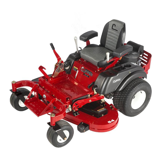
Congratulations for buying a Country Clipper product. Your Country Clipper Zero Turn Radius Riding Mower was
designed and built to provide long and trouble free service. Keep in mind that it, like any other mechanical device, can
be potentially dangerous if used improperly, and hazard control and accident prevention are dependent upon the
awareness, concern, prudence, and proper training of personnel involved in the operation, transport, maintenance, and
storage of the equipment. Study this manual and pay special attention to the important Safety Precautions on pages 3-
5. Following these instructions will help you continue to enjoy the trouble-free performance expected of the Country
Clipper product.
P-13378
Advertisement
Table of Contents

Related Manuals for Country Clipper XLT C300


Summary of Contents for Country Clipper XLT C300
- Page 1 Safety Instructions & Operators Manual Congratulations for buying a Country Clipper product. Your Country Clipper Zero Turn Radius Riding Mower was designed and built to provide long and trouble free service. Keep in mind that it, like any other mechanical device, can...
-
Page 2: Table Of Contents
TABLE OF CONTENTS MODEL NUMBER’S & SERIAL NUMBER’S ..............2 SAFETY ............................ 3 ACCIDENT PATTERNS TO AVOID ......................3 SAFETY INSTRUCTIONS AND RECOMMENDATIONS ..............3 SAFETY INTERLOCK SYSTEM ......................4 START UP AND OPERATION ....................5 CHECKLIST BEFORE OPERATION ...................... 5 CONTROL LOCATIONS JOYSTICK MODELS ................... -
Page 3: Model Number's & Serial Number's
MODEL NUMBER’S & SERIAL NUMBER’S Date of Purchase: ____________________________________________ Mower Model Number: ____________________________________________ Mower Serial Number: ____________________________________________ Engine Spec Number: ____________________________________________ Hydro Serial Number (RH): ____________________________________________ Hydro Serial Number (LH): ____________________________________________... -
Page 4: Safety
5. BEGINNING OPERATORS SHOULD LEARN waiting for the blades to completely stop. HOW TO STEER the Country Clipper Zero Turn II. PROPELLED OBJECTS -- Sticks, rocks, wires, Radius Mower before attempting to mow. Start... -
Page 5: Safety Interlock System
SAFETY INTERLOCK SYSTEM 20. MOWER SHOULD BE STOPPED AND Your Country Clipper Zero Turn Radius Mower is INSPECTED FOR DAMAGE after striking a foreign equipped with switches interlocked for your safety. object and the damage should be repaired before restarting and operating the equipment. -
Page 6: Start Up And Operation
CONTROL LOCATIONS START UP AND OPERATION JOYSTICK MODELS CHECKLIST BEFORE OPERATION Choke Blade Clutch Switch 1. Make sure fuel tank is full. Use regular unleaded gasoline (see engine owner’s manual for more details). WARNING HANDLE GASOLINE WITH CARE -- IT IS HIGHLY FLAMMABLE. -
Page 7: Operation Joystick Models
SLOPE; DRIVE FORWARD WHEN DESCENDING. IMPORTANT: 13. TO STOP: Until the operator is familiar with the Country Clipper Zero Turn Radius Mower, he/she should follow these A. Move Joystick Control Lever to neutral position recommendations: 1) Disengage the mower blades. -
Page 8: Operation Twinstick Models
Twinstick Control IMPORTANT: Throttle Lever (RH) Until the operator is familiar with the Country Clipper Zero Turn Radius Mower, he/she should follow these Cut Height recommendations: 1) Disengage the mower blades. Adjust. Lever 2) Go very slowly until thoroughly familiar with the machine. -
Page 9: Operation Free Wheel
10. BRAKING: To brake mower, gently move the OPERATION Steering Control Levers in the direction opposite to FREE WHEEL travel. NOTE: If the parking brake is engaged with 1. TO FREE WHEEL: the Steering Control Lever(s) in the “IN” position the engine will stop. -
Page 10: Mowing Recommendations
MOWER TRANSPORT MOWING RECOMMENDATIONS RECOMMENDATIONS 1. Keep mower blades sharp. 1. SECURING THE DECK FOR TRANSPORT: 2. Make sure deck and discharge are clean. A. Place the deck in the highest cut setting. It is CAUTION recommended that the Cut Height Lever be allowed to rest against the Cut Height Stop Pin. -
Page 11: Maintenance
MAINTENANCE CAUTION BEFORE PERFORMING ANY MAINTENANCE, TURN OFF ENGINE REMOVE KEY AND DISCONNECT SPARK PLUGS. USE EXTREME CARE WHEN WORKING ON MACHINERY. DO NOT WEAR WATCHES OR JEWELRY. DO NOT WEAR LOOSE FITTING CLOTHES, AND OBSERVE ALL COMMON SAFETY PRACTICES WITH TOOLS. MAINTENANCE SCHEDULE Maintenance Service Interval Maintenance Procedure... -
Page 12: Maintenance Instructions
STOP ENGINE, REMOVE IGNITION KEY AND in your Country Clipper Zero Turn Radius Mower SPARK PLUGS FOR SAFETY. information packet. A. Remove bolt and blade washer mounting blade NOTE: Air intake screen must be kept clean. - Page 13 7. PARKING BRAKE ADJUSTMENT: D. While holding the Joystick Control Lever firmly in the full speed forward position shorten the linkage A. Move Parking Brake Lever to the “OFF” to the right side transmission by rotating the position. coupling nut until the transmission control plate just B.
- Page 14 2. SETTING NEUTRAL: 3. JOYSTICK CONTROL LEVER SENSITIVITY ADJUSTMENT: If, with the Joystick Control Lever in the DOWN To change the sideways turning response, adjust (“Neutral”) or start position and the engine as follows: running the mower moves or travels, it is necessary to adjust neutral.
- Page 15 TWINSTICK ADJUSTMENT 2. SETTING THE OPERATOR HANDLES: A. There are three positional adjustments for the 1. SETTING NEUTRAL: operator hands. The length or height of the A. Each twin lever control is linked directly to the handles has two available positions. Mount the transmission control plate via an adjustable handles in the upper set of holes or the lower length ball joint rod-end linkage.
-
Page 16: Hydrostatic Transmission
G. After all the oil is drained out, replace the filter (use part # H-2567 when ordering from Country Clipper).Wipe off the filter base surface, apply a film of new oil to the gasket of the new filter and hand tighten ¾ to one full... -
Page 17: Procedure For Raising And Lowering The Deck For Servicing
D. Lift the nose of the deck until the deck is fully PROCEDURE FOR RAISING AND upright. Lifting the deck can be made easier if LOWERING THE DECK FOR SERVICING another person puts downward pressure on 1. RAISING THE DECK TO THE SERVICING the rear of the mower. - Page 18 MOWER SHOWN IN OPERATING POSITION. Joystick Control Lever Cut Height Lever Grease Zerk Deck Belt Tension Lever Front Step Deck Lift Handle MOWER SHOWN IN SERVICING POSITION. Cut Height Lever Flip up front Step Front Caster Wheels positioned Forward. Deck raised to service position Engine to Deck Belt Removed from Clutch...
-
Page 19: Leveling The Deck
4. Measure from the ground to the front blade tip of each outside blade. These measurements should be within 1/8” of each other. (NOTE: To simplify this measuring, an optional Blade Measuring Tool, part number 629-374A is available from your local “Country Clipper dealer) Clamp Plate... -
Page 20: Trouble Shooting Check List
TROUBLE SHOOTING CHECK LIST 1. ENGINE WON’T TURN OVER: Mower blades engaged --------------------------------------------------------------------------------- disengage blades Drive not in neutral -------------------------------------------------------- move Control Lever(s) to neutral position Blown fuse --------------------------------------------------------------------------------------------------------- replace fuse Dead battery ----------------------------------------------------------------------------------------------- charge or replace Solenoid --------------------------------------------------------------------------------------------------------- consult dealer Ignition switch -------------------------------------------------------------------------------------------------- consult dealer Starter ------------------------------------------------------------------------------------------------------------ consult dealer 2. -
Page 21: Belt Routings
TROUBLE SHOOTING CHECK LIST CON’T 11. TRANSMISSION LOSES POWER OR TRANSMISSIONS OVER HEATS: Transmission damage -----------------------------------------------------------------------------------------consult dealer 12. MOWER TRANSMISSION DOES NOT ENGAGE RIGHT AND/OR LEFT HAND: Transmission Free Wheel engaged--------------------------------------------------------------disengage Free Wheel Loose or damage Control Linkage --------------------------------------------------------------------------consult dealer Low Transmission oil -------------------------------------------------------------------------------------------consult dealer 13. -
Page 22: Notes / Service Records
NOTES / SERVICE RECORDS: DATE SERVICE WORK COMPLETED... -
Page 23: Notes / Service Records
NOTES / SERVICE RECORDS: DATE SERVICE WORK COMPLETED... - Page 24 Safety Instructions & Operators Manual Country Clipper Division Shivvers Manufacturing Inc. 613 W. English St. Corydon, IA 50060-0467 Ph. 641-872-2544 Fax. 641-872-1593 P-13378...
Need help?
Do you have a question about the XLT C300 and is the answer not in the manual?
Questions and answers
Where do I purchase replacement blades for my mower model 2q660KOJ-C300