Table of Contents
Advertisement
Quick Links
Advertisement
Table of Contents

Related Manuals for Kobold DFT Series


Summary of Contents for Kobold DFT Series
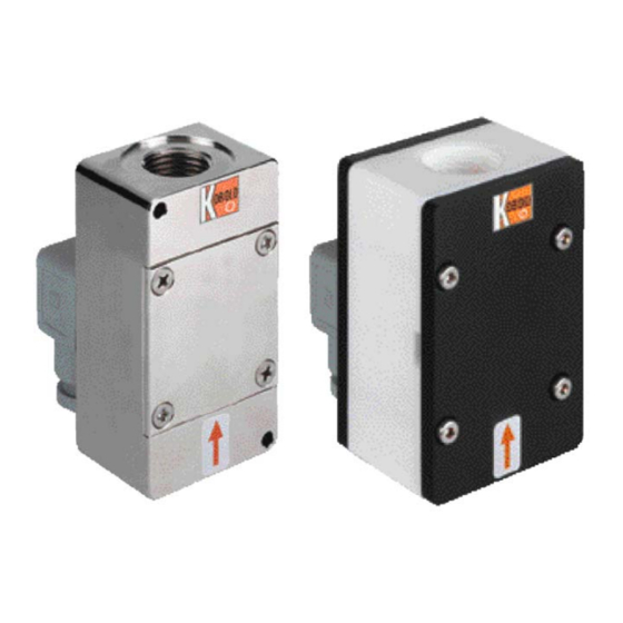
- Page 1 Operating Instructions Rotating Vane Flow Meter Model: DFT...
-
Page 2: Table Of Contents
Order Codes ....................13 Dimensions ....................14 EU Declaration of Conformance ..............16 Manufactured and sold by: Kobold Messring GmbH Nordring 22-24 D-65719 Hofheim Tel.: +49(0)6192-2990 Fax: +49(0)6192-23398 E-Mail: info.de@kobold.com Internet: www.kobold.com page 2 DFT K02/0316... -
Page 3: Note
2. Note Please read these operating instructions before unpacking and putting the unit into operation. Follow the instructions precisely as described herein. The devices are only to be used, maintained and serviced by persons familiar with these operating instructions and in accordance with local regulations applying to Health &... -
Page 4: Operating Principle
KOBOLD flow meters/monitors work with this proven principle and offer many benefits. The heart of the new KOBOLD vane is an embedded ring magnet; it is hermetically sealed from the flow medium. It transfers, in a non-contacting manner, the rotary motion of the vane to a Hall sensor attached to the case (in order to save space). -
Page 5: Electrical Connection
7. Electrical Connection 7.1 General Caution! Make sure that the voltage values of your system correspond with the voltage values of the measuring unit. Make sure that the supply wires are de-energized. Connect the power supply and the evaluation oft the output signal to the pins of the plug described below. -
Page 6: Ma-Electronics (Dft
7.4 MA-Electronics (DFT-...M..) Cable connection Wire no. 1 = power supply (-)~ Wire no. 2 = power supply (+)~ Wire no. 3 = anlaogue output (+) 7.5 WM-Electronics (DFT-...W..) off state or in alarm condition Cable connection Wire no: 1= power supply (-) Wire no. -
Page 7: Dft-K/E/G (Only With Cable Connection)
7.6 DFT-K/E/G (only with cable connection) Wire DFT-K DFT-E DFT-G number +24 V +24 V +24 V 4-20 mA 4-20 mA 4-20 mA d.c. *) d.c. *) Ctrl 1 *) d.c. *) Reset TM *) Ctrl 2 *) relay S1 N/O relay S1 N/O relay S1 N/O relay S1 COM... -
Page 8: Wm Electronic (Dft
8.2 WM Electronic (DFT-...W..) The device is delivered ready for use. The electronics have been calibrated and fine tuned to the sensor. The calibrating screws ("Zero" and "Range"), next to the scale button, must not be adjusted by the customer. Adjustment by the customer means that a re-calibration is necessary (and this is chargeable). -
Page 9: K/E/G-Electronic
Setting the limit value Loosen the 4 screws on the transparent electronics cover and remove it. The limit value is set using the value setter. Turn the value setter to the desired limit value on the scale to the reference line to the left of the scale on the font plate. -
Page 10: Technical Information
10. Technical Information Sensor Measuring accuracy: 2.5 % f. s. 5 % f. s. (DFT-...0000) Medium temperature: -20 to +80 °C Ambient temperature: -20 to +80 °C Max. operating pressure: 5 bar (PTFE housing) 16 bar (brass housing) Max. pressure loss: see table Protection type: IP 65... - Page 11 Analogue output (L electronics) Power supply: 24 V ±20 % Output: 0-20 mA or 4-20 mA, 3-wire or 2-wire (2-wire 4-20 mA only) Max. load: 500 Ohm. Electrical connection: connector DIN 43 650 Analogue output (MA electronics) Power supply: 24 V +15% / -10 % 24/115/230 V ±20 %...
-
Page 12: Maintenance
Counter-Electronics “E” Display: 2 x 8-digit LCD module, illuminated, total, part and flow quantity; units of measurement selectable Quantity meter: 8-digit Power supply: 24 V ±20 % Current consumption: approx. 100 mA Electrical connection: 10-pole cable connection Analogue output: 0(4)…20 mA selectable Load: 0…500 Ω... -
Page 13: Order Codes
12. Order Codes Order Details (Example: DFT-1101 G2 F400) Measuring range Model Connection [L/min] female thread Brass housing PTFE housing Brass housing PTFE housing ceramic axle ceramic axle sapphire axle sapphire axle 0.1 - 0.5 ..G2.. = G 1/4 DFT-1101.. DFT-1301.. -
Page 14: Dimensions
13. Dimensions page 14 DFT K02/0316... - Page 15 DFT with MA/WM/K electronics (E/G electronics) DFT K02/0316 page 15...
-
Page 16: Eu Declaration Of Conformance
14. EU Declaration of Conformance We, KOBOLD Messring GmbH, Hofheim-Ts, Germany, declare under our sole responsibility that the product: Rotating Vane Flow Meter Model: DFT to which this declaration relates is in conformity with the standards noted below: EN 61000-6-4:2011...
Need help?
Do you have a question about the DFT Series and is the answer not in the manual?
Questions and answers