Advertisement
Quick Links
April, 2002
KI
1330 Bellevue Street
P.O. Box 8100
Green Bay, Wisconsin 54308-8100
www.ki.com
TEL (920) 468-8100
FAX (920) 468-0280
Assembly Instructions
All Terrain
®
Mobile Furniture
Fixed-Height and Pin-Height Adjustable Tables with Eight-Screw Base Attachment
ATSW45/, ATSW57/,
ATSW63/, ATSW69
ATCC2754/, ATCC3054/
Note:
Postition longer
legs toward front
of table edge.
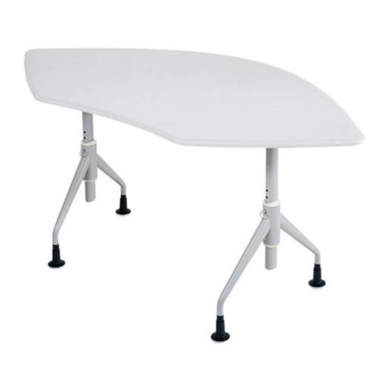
ATRC3042/, ATRC3048/, ATRC3060
ATDU50/
ATEL2745/, ATEL3658/
Assemble units as described herein only. To do otherwise may result in instability. All screws, nuts and bolts must be tightened and
checked periodically after assembly.
injury.
Illustrations and specifications are based on current product information at the time of this printing.
ATRC2448/, ATRC2460/, ATRC2742/,
ATRC2748/, ATRC2760/
ATDU46/
Note:
Postition longer
legs toward front
of table edge.
ATCC2448/, ATCC2748/
ATSL2745/, ATSL3658/
Failure to assemble properly, or to secure parts may result in assembly failure and
Tools Required:
#2 Phillips screwdriver
3
/
" open end wrench
4
(for tables with casters)
Hardware Included:
(8)
1
/
-20 x
3
/
" Phillips pan-head screws
4
4
with nylon patch
4 total of one of the following:
locking casters (46.5147)
non-locking casters (46.5146)
glides (10.3000.BLWH)
1. To avoid scratching the tabletop, place
it face down on a soft protective
material. Refer to the top and base
packaging labels to identify the table
model number. Identify applicable
table illustration:
2. Unpackage appropriate table base
and refer to the illustration above for
proper base/leg orientation. Set the
base in place on the underside of the
worksurface aligning attachment
holes with threaded inserts in the
worksurface tops as shown.
Note:
Front of tables are at the top
of illustration.
Advertisement

Related Manuals for KI All Terrain ATSW45


Summary of Contents for KI All Terrain ATSW45
- Page 1 1330 Bellevue Street P.O. Box 8100 Hardware Included: Green Bay, Wisconsin 54308-8100 -20 x " Phillips pan-head screws www.ki.com with nylon patch 4 total of one of the following: ATSW45/, ATSW57/, ATRC2448/, ATRC2460/, ATRC2742/, TEL (920) 468-8100 locking casters (46.5147)
- Page 2 (Figure 4). Figure 2 Figure 3 6. Carefully turn the table upright. Check that the table is flat and level. Adjust the glide heights to make minor adjustments. Part Number 13.7126 Figure 4 © KI 2002 Litho in USA Code KI-61331/KP402...