Advertisement
These spiral cutterheads are designed to replace
the straight knife cutterheads from most Grizzly 6"
and 8" jointers.
The total procedure of changing the cutterheads
and setting up the jointer takes approximately
one hour. The job consists of removing the old
cutterhead, installing and shimming the new spi-
ral cutterhead, and readjusting the outfeed table
even with the knife edges at TDC (top dead cen-
ter). Call Technical Support at (570) 546-9663 if
you need help.
Recommended Tools:
Wrench 8 x 14mm ............................................. 1
Precision Straightedge (Figure 1) ..................... 1
Feeler Gauge Set
Pair of Heavy Leather Gloves ........................... 1
G9644—12" Precision Straightedge
H2675—16" Precision Straightedge
Is your straightedge really straight? These grade
00 heavy-duty stainless steel straightedges are
manufactured to DIN874 standards for profes-
sional results in set-up and inspection work.
Figure 1. Precision straightedges.
WARNING: NO PORTION OF THIS MANUAL MAY BE REPRODUCED IN ANY SHAPE
OR FORM WITHOUT THE WRITTEN APPROVAL OF GRIZZLY INDUSTRIAL, INC.
COPYRIGHT © JUNE, 2005 BY GRIZZLY INDUSTRIAL, INC.
#TR7277 PRINTED IN TAIWAN
6" & 8" SPIRAL
CUTTERHEADS
MODEL H7590/H7591
INSTRUCTION SHEET
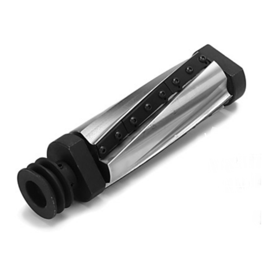
Inventory:
Cutterhead ......................................................... 1
Bearing Block Studs .......................................... 2
Alignment Tools ................................................. 2
T-Handle Hex Wrench 4mm .............................. 1
Flat Washers
⁄
" ................................................ 2
3
8
Hex Nuts
⁄
"-24 ................................................. 2
3
8
Figure 2. Spiral cutterhead inventory.
Installation:
1.
Disconnect/unplug jointer from power!
2.
Remove the jointer fence and cutterhead
guard.
3.
Remove the V-belts from the pulleys.
4.
Lower both beds to make enough room for
the cutterhead to come out, as shown in
Figure 3.
Note: When lowering, make sure that the
fence support does not come in contact with
the cutterhead pulley.
Advertisement
Table of Contents

Subscribe to Our Youtube Channel
Related Manuals for Grizzly H7590


Summary of Contents for Grizzly H7590
- Page 1 Figure 1. Precision straightedges. COPYRIGHT © JUNE, 2005 BY GRIZZLY INDUSTRIAL, INC. WARNING: NO PORTION OF THIS MANUAL MAY BE REPRODUCED IN ANY SHAPE OR FORM WITHOUT THE WRITTEN APPROVAL OF GRIZZLY INDUSTRIAL, INC. #TR7277 PRINTED IN TAIWAN...
- Page 2 Bearing Block Bearing Block Stud Figure 3. Jointer disassembly Steps 1– 4. Figure 5. Cutterhead removed. Install the included bearing block studs into Remove the nut on the bearing block stud, as the spiral cutterhead bearing blocks, and shown in Figure 4, and repeat on the other install the cutterhead (Figure 6).
- Page 3 ������������ ������������� Figure 9. Setting outfeed table height with a straightedge. Figure 7. Checking cutterhead parallelism with a 14. Install the cutterhead guard back over the straightedge (repeat at both ends of cutterhead). cutterhead, making sure that the spring ten- sion in the guard is properly set so the guard 10.
- Page 4 H7590 Parts Breakdown and List �� � ��� ��� � �� � �� � �� � �� �� � � � � PART # DESCRIPTION PART # DESCRIPTION PH7590001 6" SPIRAL CUTTERHEAD PSBS12M BUTTON HD CAP SCR M6-1 X 14...
Need help?
Do you have a question about the H7590 and is the answer not in the manual?
Questions and answers