Grizzly EXTREME G1033X Owner's Manual
20 5hp spiral cutterhead planer
Hide thumbs
Also See for EXTREME G1033X:
- Owner's manual (76 pages) ,
- Parts list (9 pages) ,
- Manual (10 pages)
Table of Contents
Advertisement
Quick Links
MODEL G1033X
20" 5HP SPIRAL CUTTERHEAD
PLANER
OWNER'S MANUAL
Copyright © FEBrUAry, 2006 By grizzly indUstriAl, inC., rEvisEd April, 2010 (tr)
WARNING: NO PORTION Of THIS MANUAL MAy bE REPRODUCED IN ANy SHAPE
OR fORM WITHOUT THE WRITTEN APPROvAL Of GRIzzLy INDUSTRIAL, INC.
For modEls mAnUFACtUrEd sinCE 4/10 #Bl7969 printEd in ChinA
Download from Www.Somanuals.com. All Manuals Search And Download.
Advertisement
Table of Contents

Related Manuals for Grizzly EXTREME G1033X


Summary of Contents for Grizzly EXTREME G1033X
- Page 1 20" 5HP SPIRAL CUTTERHEAD PLANER OWNER'S MANUAL Copyright © FEBrUAry, 2006 By grizzly indUstriAl, inC., rEvisEd April, 2010 (tr) WARNING: NO PORTION Of THIS MANUAL MAy bE REPRODUCED IN ANy SHAPE OR fORM WITHOUT THE WRITTEN APPROvAL Of GRIzzLy INDUSTRIAL, INC.
- Page 2 This manual provides critical safety instructions on the proper setup, operation, maintenance and service of this machine/equipment. Failure to read, understand and follow the instructions given in this manual may result in serious personal injury, including amputation, electrocution or death. The owner of this machine/equipment is solely responsible for its safe use.
-
Page 3: Table Of Contents
Table of Contents INTRODUCTION ..........2 SECTION 5: ACCESSORIES ......22 manual Accuracy ........... 2 SECTION 6: MAINTENANCE ......24 Contact info............ 2 schedule ............24 identification ........... 3 Cleaning ............24 machine data sheet ........4 v-Belts ............24 SECTION 1: SAfETy ........ -
Page 4: Introduction
Your Machine For your convenience, we post all available man- uals and manual updates for free on our website at www.grizzly.com. Any updates to your model of machine will be reflected in these documents as soon as they are complete. -
Page 5: Identification
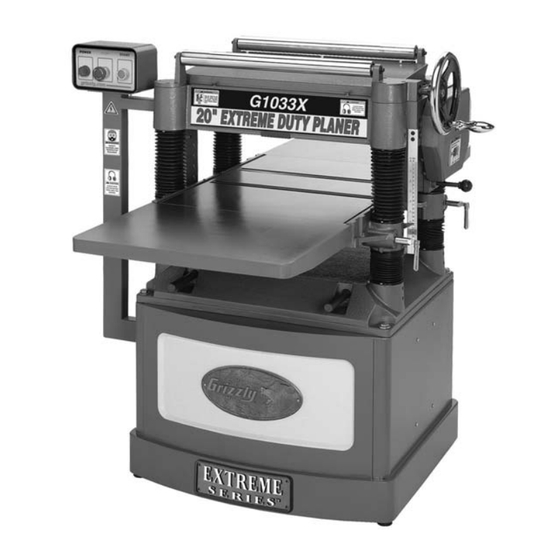
Identification figure 1. g1033X identification. A. Control Box and panel b. return rollers C. table height handwheel D. gearbox E. table height scale speed Control Knob G. table locks H. lifting Bar Extension Wing dust hood K. v-Belt Cover motor and magnetic switch Access panel model g1033X (mfg. -
Page 6: Machine Data Sheet
Machine Data Sheet MACHINE DATA SHEET Customer Service #: (570) 546-9663 · To Order Call: (800) 523-4777 · Fax #: (800) 438-5901 MODEL G1033X 20" 5 HP SPIRAL CUTTERHEAD PLANER Product Dimensions: Weight................................875 lbs. Length/Width/Height..........................56 x 39 x 41 in. Foot Print (Length/Width).......................... - Page 7 Cutterhead Info Cutterhead Type............................Spiral Cutterhead Dia............................3-1/4 in. No. Of Cutter Spirals............................4 No. Of Indexable Cutters..........................96 Cutter Insert Type..................... 30 deg. Indexable Carbide Cutter Insert Size Length......................... 15 mm Cutter Insert Size Width........................... 15 mm Cutter Insert Size Thickness........................2.5 mm Table Info Table Movement............................
-
Page 8: Section 1: Safety
SECTION 1: SAfETy For Your Own Safety, Read Instruction Manual Before Operating this Machine The purpose of safety symbols is to attract your attention to possible hazardous conditions. This manual uses a series of symbols and signal words intended to convey the level of importance of the safety messages. - Page 9 safety instructions for machinery 7. Only allOw trained and prOp- 16. remOve chucK Keys Or adJustinG erly supervised persOnnel tO tOOls. Make a habit of never leaving Operate machinery. Make sure chuckkeysorotheradjustmenttoolsin/on operationinstructionsaresafeandclearly themachine—especiallynearspindles! understood. 17. damaGed machinery.Checkforbind- 8.
-
Page 10: Additional Safety For Planers
Additional Safety for Planers INSTRUCTION MANUAL: this machine CUTTING LIMITATIONS: the planer may presents significant safety hazards to kick out a workpiece at the operator or be untrained users. read/understand this entire damaged if pushed beyond these limits: manual before starting the planer. •... -
Page 11: Section 2: Circuit Requirements
SECTION 2: CIRCUIT REQUIREMENTS 220v Single-Phase Power Connection Device the type of plug required to connect your machine to power depends on the type of service you cur- rently have or plan to install. We recommend using the plug shown in figure 2. Serious personal injury could occur if you connect the machine to the power source L6-30 LOCKING... -
Page 12: Section 3: Set Up
SECTION 3: SET UP Items Needed for Set Up This machine presents serious injury hazards to untrained users. Read through this entire manu- the following items are needed to complete the al to become familiar with set up process, but are not included with your the controls and opera- machine: tions before starting the... -
Page 13: Inventory
Inventory After all the parts have been removed from the crate, you should have the following items: box Inventory (figure 3) A. planer Unit ..........1 b. dust hood ..........1 C. table Extension Wings ....... 2 D. handwheel ..........1 figure 3. -
Page 14: Hardware Recognition Chart
Hardware Recognition Chart -12- model g1033X (mfg. since 4/10) Download from Www.Somanuals.com. All Manuals Search And Download. -
Page 15: Cleanup
Cleanup Gasoline and petroleum products have low flash The unpainted surfaces of your machine are points and can explode coated with a heavy-duty rust preventative that or cause fire if used to prevents corrosion during shipment and storage. clean machinery. Avo i d u sing t h e s e p r o du c t s This rust preventative has been your machine's to cl e a n m ac hin e r y. -
Page 16: Site Considerations
Site Considerations Weight Load Physical Environment Refer to the Machine Data Sheet for the weight The physical environment where your machine of your machine. Make sure that the surface upon is operated is important for safe operation and which the machine is placed will bear the weight the longevity of its components. -
Page 17: Moving & Placing Planer
Moving & Placing Extension Wings Planer Components and Hardware Needed: table Extension Wings ........2 hex Bolts m8-1.25 x 25 ........6 set screws m8-1.25 x 20 ........6 The Model G1033X is a To attach the table extension wings: heavy machine. -
Page 18: Handwheel
Handwheel Dust Hood Components and Hardware Needed: Components and Hardware Needed: handwheel............1 dust hood ............1 handwheel Bushing .......... 1 Flange Bolts m6-1 x 12 ........6 handwheel handle ..........1 hex nut m12-1.75 ..........1 Flat Washer 12mm ..........1 Key 4 x 4 x 10 ............ -
Page 19: Gearbox Oil Level
Gearbox Oil Level Connecting to Power now is the time to connect your planer to the Before starting your machine for the first time, power source. make sure you have read CIRCUIT make sure the gearbox has oil. the proper oil REQUIREMENTS on Page 9, before doing so. -
Page 20: Tighten V-Belts
Tighten v-belts Recommended Adjustments the final step in the set up process must be done after approximately 16 hours of operation. during For your convenience, the adjustments listed this first 16 hours, the v-belts will stretch and seat below have been performed at the factory and into the pulley grooves. -
Page 21: Section 4: Operations
Regardless of the con- adjust the table height as necessary to take tent in this section, Grizzly Industrial will a lighter or heavier pass, depending on your not be held liable for accidents caused by needs. -
Page 22: Operation Tips
Operation Tips feed Speed • inspect lumber for defects, warping, cup- the infeed and outfeed rollers power the stock ping, twisting, and for foreign objects (nails, through the planer while keeping boards flat and providing a consistent rate of movement. staples, imbedded gravel, etc,). -
Page 23: Bed Rollers
bed Rollers To adjust the bed rollers: lower the table to give yourself at least 4" of working room below the cutterhead. Adjustment Height Range ..0.002"–0.020" loosen the locking set screws (figure 14) Tools Needed: above the roller adjusters (4 total). hex Wrench 3mm .......... -
Page 24: Section 5: Accessories
SECTION 5: ACCESSORIES G1738—Rotacator™ Precision Planer Tool H9816—Power Twist v-belt - 3/8" x 60" ® the rotacator is a dial indicator on a magnetic smooth running with less vibration and noise base and is designed for quickly and accurate- than solid belts. the power twist v-belts can ®... - Page 25 T20446—Ear Plugs 200 Pair - 31db A must have if you or employees operate for hours at a time. H4978 T20446 H4979 figure 22. grizzly dial Calipers. ® figure 20. hearing protection assortment. -23- model g1033X (mfg. since 4/10) Download from Www.Somanuals.com. All Manuals Search And Download.
-
Page 26: Section 6: Maintenance
SECTION 6: MAINTENANCE v-belts Always disconnect power to the machine before v-belt removal and replacement is simply a mat- performing maintenance. ter of loosening the v-belts, rolling them off of failure to do this may the pulleys, replacing them with new belts, then result in serious person- retensioning them. -
Page 27: Lubrication
Fill vibration, which will increase when the machine is put under load. Bearings are standard sizes and can be replaced through grizzly. drain proper lubrication of other planer components are figure 24. gearbox oil drain/fill locations. -
Page 28: Section 7: Service
SECTION 7: SERvICE review the troubleshooting and procedures in this section to fix your machine if a problem develops. if you need replacement parts or you are unsure of your repair skills, then feel free to call our technical support at (570) 546-9663. - Page 29 Cutting symptom possible Cause possible solution 1. lower the bed rollers (Page 20). Excessive snipe (gouge in the end of 1. one or both of the bed rollers are set the board that is uneven with the rest of too high. the cut).
-
Page 30: Rotating/Changing Carbide Cutters
Rotating/Changing To rotate or change a carbide cutter: Carbide Cutters 1. disConnECt thE plAnEr From thE poWEr soUrCE! 2. remove any sawdust from the head of the Tools Needed: carbide cutter torx screw. t-handle Wrench w/t-25 torx driver ....1 3. -
Page 31: Chain Tension
Chain Tension re-tighten the two locking bolts. Check chain lubrication. refer to SECTION 6: MAINTENANCE on Page 23 for further Tools Needed: details. phillips screwdriver #2 ........1 Wrench or socket 14mm ........1 Table Parallelism the chain drive transfers movement from the handwheel to elevate the table. - Page 32 how the table sits in relation to the head casting NOTICE from front-to-back is also important (see figure 29). Because the feed rollers, pressure bar, and When making adjustments, tighten fasten- chip breaker will be adjusted off the table position, ers after each step to ensure the accuracy the tolerances on the front-to-back positioning are of your tests.
-
Page 33: Internal Component Heights
Internal Component repeat Steps 4–6 with each sprocket that needs to be adjusted until the table-to- Heights cutterhead clearance is within 0.016" from one side to the other. make sure the chain is properly fitted on the Distance below Cutter Edge at *bDC sprockets, and tighten the idler sprocket and infeed roller .......... - Page 34 make sure the cutters are set correctly. infeed roller lower the table at least 4" below the head casting and lock the table in place. remove the dust port, top cover, and belt cover. nuts Using your rotacator, find BdC of any carbide insert edge by slowly rocking the cutterhead outfeed pulley back and forth, and set the rotacator...
- Page 35 To adjust the height of the infeed and outfeed remove the dust port, top cover, and belt rollers, chip breaker and pressure bar using cover. wood blocks and a feeler gauge: Adjust the table and use the feeler gauge until Build the wood blocks by cutting a strAight you have a 0.040"...
-
Page 36: Spring Tension
Spring Tension Chip Deflector Positioning Tools Needed: hex Wrench 6mm ..........1 Chip Deflector Gap Setting if planer Used w/dust Collector ...... ⁄ roller spring tension must be adjusted so that if planer Used w/o dust Collector ....⁄ feed roller pressure is uniform. roller spring ten- sion will vary, depending on the type of wood you Tools Needed: plane. -
Page 37: Scale Calibration
Scale Calibration Anti-Kickback fingers the model g1033X provides an anti-kickback Tools Needed: system as a safety feature. the anti-kickback phillips head screwdriver #2 ......1 fingers hang from a rod suspended across the Calipers ............. 1 cutterhead casting. the anti-kickback fingers should be inspected regularly. -
Page 38: Pulley Alignment
Pulley Alignment loosen the fasteners that hold the motor to the brackets shown in figure 42 just enough to allow the motor to be repositioned. Tools Needed: straightedge ............1 Wrench 14mm ............2 phillips screwdriver #2 ........1 proper pulley alignment (see figure 41) prevents premature belt wear. -
Page 39: Electrical Components
Electrical Components Control Panel Motor Junction box Magnetic Switch -37- model g1033X (mfg. since 4/10) Download from Www.Somanuals.com. All Manuals Search And Download. -
Page 40: Wiring Diagram
COLOR KEY Control Box BLACK WHITE GREEN Ground START STOP POWER BLUE BROWN MAGNETIC SWITCH View this page in color at www.grizzly.com. R/1/L1 S/3/L2 T/5/L3 15/13 MA-30 220V U/2/T1 V/4/T2 W/6/T3 14/16 The motor wiring shown here is RA-30 current at the time of printing, but it... -
Page 41: Headstock Parts Breakdown
Headstock Parts breakdown -39- model g1033X (mfg. since 4/10) Download from Www.Somanuals.com. All Manuals Search And Download. - Page 42 Headstock Parts List REF PART # DESCRIPTION PART # DESCRIPTION P1033X001 ROUND KNOB 5/16-18 P1033X035 EXTENSION SPRING 8.5 X 14 P1033X002 V-BELT COVER P1033X036 HANGER PVM59 V-BELT M59 3L590 P1033X038 LEFT BACKING PLATE P1033X004 STUD PSS13M SET SCREW M10-1.5 X 12 PB09M HEX BOLT M8-1.25 X 20 PSS14M...
- Page 43 REF PART # DESCRIPTION REF PART # DESCRIPTION P1033X064 SHAFT 15.875 X 710 91-7 PW03M FLAT WASHER 6MM P1033X065 CHIP BREAKER P1033X093 OIL PLUG P1033X066 SPROCKET P1033X094 OIL SEAL 28 X 40 X 8 PR03M EXT RETAINING RING 12MM P1033X095 GEAR BOX PEC05M E-CLIP 15MM...
- Page 44 Table Parts breakdown -42- model g1033X (mfg. since 4/10) Download from Www.Somanuals.com. All Manuals Search And Download.
- Page 45 Table Parts List REF PART # DESCRIPTION REF PART # DESCRIPTION PW01M FLAT WASHER 8MM PR05M EXT RETAINING RING 15MM PSS13M SET SCREW M10-1.5 X 12 P6202ZZ BEARING 6202ZZ PR03M EXT RETAINING RING 12MM PR21M INT RETAINING RING 35MM P1033X107 EXTENSION WING P1033X146 SPROCKET...
-
Page 46: Stand/Motor Parts Breakdown
Stand/Motor Parts breakdown 169V2-7 169V2-2 169V2-3 169V2-4 169V2-6 169V2-5 169V2-8 169V2-1 169V2 39-1 39-2 39-4 39-3 -44- model g1033X (mfg. since 4/10) Download from Www.Somanuals.com. All Manuals Search And Download. - Page 47 CABINET STAND P1033X229 NYLOCK HEX BOLT M8-1.25 X 20 P1033X123 FRONT COVER PS38M PHLP HD SCR M4-.7 X 10 PN06M HEX NUT M5-.8 G8589 GRIZZLY NAMEPLATE-LARGE P1033X125 STRAIN RELIEF P1033X220 STRAIN RELIEF P1033X126 START SWITCH P1033X221 POWER CORD 10G 3W P1033X127...
-
Page 48: Labels & Cosmetic
MUST maintain the original location and readability of the labels on the machine. If any label is removed or becomes unreadable, REPLACE that label before using the machine again. Contact Grizzly at (800) 523-4777 or www.grizzly.com to order new labels. -46- model g1033X (mfg. - Page 49 Would you recommend Grizzly Industrial to a friend? _____ Yes _____No Would you allow us to use your name as a reference for Grizzly customers in your area? Note: We never use names more than 3 times. _____ Yes _____No 10.
- Page 50 Place Stamp Here GRIZZLY INDUSTRIAL, INC. P.O. BOX 2069 BELLINGHAM, WA 98227-2069 FOLD ALONG DOTTED LINE Send a Grizzly Catalog to a friend: Name_______________________________ Street_______________________________ City______________State______Zip______ TAPE ALONG EDGES--PLEASE DO NOT STAPLE Download from Www.Somanuals.com. All Manuals Search And Download.
-
Page 51: Warranty And Returns
WARRANTY AND RETURNS Grizzly Industrial, Inc. warrants every product it sells for a period of 1 year to the original purchaser from the date of purchase. This warranty does not apply to defects due directly or indirectly to misuse, abuse, negligence, accidents, repairs or alterations or lack of maintenance. - Page 52 Buy Direct and Save with Grizzly – Trusted, Proven and a Great Value! ® ~Since 1983~ Visit Our Website Today For Current Specials! ORDER 24 HOURS A DAY! 1-800-523-4777 Download from Www.Somanuals.com. All Manuals Search And Download.
- Page 53 Free Manuals Download Website h p://myh66.com h p://usermanuals.us h p://www.somanuals.com h p://www.4manuals.cc h p://www.manual-lib.com h p://www.404manual.com h p://www.luxmanual.com h p://aubethermostatmanual.com Golf course search by state h p://golfingnear.com Email search by domain h p://emailbydomain.com Auto manuals search h p://auto.somanuals.com TV manuals search h p://tv.somanuals.com...
Need help?
Do you have a question about the EXTREME G1033X and is the answer not in the manual?
Questions and answers