Table of Contents
Advertisement
Quick Links
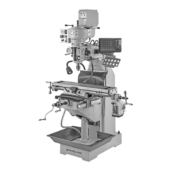
MODEL G0961
8" X 36" VS KNEE MILL
w/POWER FEED & DRO
OWNER'S MANUAL
(For models manufactured since 06/23)
COPYRIGHT © DECEMBER, 2023 BY GRIZZLY INDUSTRIAL, INC.
WARNING: NO PORTION OF THIS MANUAL MAY BE REPRODUCED IN ANY SHAPE
OR FORM WITHOUT THE WRITTEN APPROVAL OF GRIZZLY INDUSTRIAL, INC.
#MNLW22685 PRINTED IN CHINA
V1.12.23
***Keep for Future Reference***
Advertisement
Table of Contents

Related Manuals for Grizzly G0961


Summary of Contents for Grizzly G0961
- Page 1 (For models manufactured since 06/23) COPYRIGHT © DECEMBER, 2023 BY GRIZZLY INDUSTRIAL, INC. WARNING: NO PORTION OF THIS MANUAL MAY BE REPRODUCED IN ANY SHAPE OR FORM WITHOUT THE WRITTEN APPROVAL OF GRIZZLY INDUSTRIAL, INC. #MNLW22685 PRINTED IN CHINA V1.12.23...
- Page 2 This manual provides critical safety instructions on the proper setup, operation, maintenance, and service of this machine/tool. Save this document, refer to it often, and use it to instruct other operators. Failure to read, understand and follow the instructions in this manual may result in fire or serious personal injury—including amputation, electrocution, or death.
-
Page 3: Table Of Contents
Table of Contents INTRODUCTION ..........2 SECTION 5: ACCESSORIES ......36 Contact Info ........... 2 SECTION 6: MAINTENANCE ......37 Manual Accuracy ........... 2 Schedule ............37 Left Front View Identification ......3 Cleaning & Protecting ........37 Right Front View Identification ....... 4 Lubrication ........... -
Page 4: Introduction
Use this machine with respect and caution to decrease the risk of operator injury. If normal safety pre- cautions are overlooked or ignored, seri- ous personal injury may occur. Model G0961 (Mfd. Since 06/23) -
Page 5: Left Front View Identification
(1 of 2) Quill & Spindle Handwheel Coolant Nozzle Work Light Switch (1 of 2) X-Axis Ball Handle X-Axis Ball Handle X-Axis Table Lock (1 of 2) Y-Axis Ball Handle Knee One-Shot Oiler Splash Pan Model G0961 (Mfd. Since 06/23) -
Page 6: Right Front View Identification
V-Belt Access Cover Control Panel 2-Axis Fine Downfeed Handwheel Work Light Coarse Downfeed Lever Power Feed Limit Switch Quill Lock Lever X-Axis Limit Stop (1 of 2) Knee Crank Coolant Return Hose X-Axis Power Feed Model G0961 (Mfd. Since 06/23) -
Page 7: Controls & Components
Quill Lock Lever: Locks quill in vertical position. B. Spindle Speed Digital Readout: Displays spindle RPM. C. Work Light ON/OFF Switch: Turns work light ON and OFF. Light may also be turned ON/OFF using switch on light base. Model G0961 (Mfd. Since 06/23) - Page 8 Z-axis control. Table Figure 5. Ram controls. W. Ram Lock Handles: Secure ram in position. X. Ram Movement Lever: Moves ram forward/ backward along ways. Figure 4. Table controls and components. Model G0961 (Mfd. Since 06/23)
- Page 9 X-Axis Limit Stop (1 of 2): Limits X-axis table travel (one on each end of table). AA. Graduated Dial: Displays X-axis table move- ment in 0.001" increments, with each revolu- tion equaling 0.200" of travel. Model G0961 (Mfd. Since 06/23)
-
Page 10: Machine Data Sheet
MACHINE DATA SHEET Customer Service #: (570) 546-9663 · To Order Call: (800) 523-4777 · Fax #: (800) 438-5901 MODEL G0961 8" X 36" VARIABLE-SPEED KNEE MILL WITH POWER FEED AND DRO Product Dimensions: Weight................................1731 lbs. Width (side-to-side) x Depth (front-to-back) x Height..............56 x 56 x 76-1/2 in. - Page 11 The information contained herein is deemed accurate as of 7/4/2024 and represents our most recent product specifications. Model G0961 PAGE 2 OF 3 Due to our ongoing improvement efforts, this information may not accurately describe items previously purchased. Model G0961 (Mfd. Since 06/23)
-
Page 12: Section 1: Safety
Never operate under the influence of drugs or injury or blindness from flying particles. Everyday alcohol, when tired, or when distracted. eyeglasses are NOT approved safety glasses. -10- Model G0961 (Mfd. Since 06/23) - Page 13 EXPERIENCING DIFFICULTIES. If at any time debris. Make sure they are properly installed, you experience difficulties performing the intend- undamaged, and working correctly BEFORE ed operation, stop using the machine! Contact our operating machine. Technical Support at (570) 546-9663. -11- Model G0961 (Mfd. Since 06/23)
-
Page 14: Additional Safety For Milling Machines
OFF to avoid a possible sudden startup use. This will prevent them from being thrown by once power is restored. the spindle upon startup. -12- Model G0961 (Mfd. Since 06/23) -
Page 15: Section 2: Power Supply
-13- Model G0961 (Mfd. Since 06/23) - Page 16 Do not modify or use an adapter on the plug provided—if it will not fit the outlet, have a qualified electrician install the proper outlet with a verified ground. -14- Model G0961 (Mfd. Since 06/23)
-
Page 17: Section 3: Setup
IMPORTANT: Save all packaging materials until you are completely satisfied with the machine and have resolved any issues between Grizzly or the shipping agent. You MUST have the original pack- aging to file a freight claim. It is also extremely helpful if you need to return your machine later. -
Page 18: Inventory
⁄ "......1 G. Chuck Key ..........1 H. Open-End Wrench 17/19mm ...... 1 Hex Wrench Set 1.5–10mm......1 Drill Chuck Arbor R8-JT3 ......1 K. Splash Pan ..........1 Figure 8. Loose components. -16- Model G0961 (Mfd. Since 06/23) -
Page 19: Cleanup
Figure 9. T23692 Orange Power Degreaser. Repeat Steps 2–3 as necessary until clean, then coat all unpainted surfaces with a quality metal protectant to prevent rust. -17- Model G0961 (Mfd. Since 06/23) -
Page 20: Site Considerations
Only install in an Shadows, glare, or strobe effects that may distract access restricted location. or impede the operator must be eliminated. 30" 79½" Minimum Clearance 56" = Electrical Connection Figure 10. Minimum working clearances. -18- Model G0961 (Mfd. Since 06/23) -
Page 21: Lifting & Placing
(or other lifting equipment) rated for weight of this machine. The Model G0961 requires the use of lifting equipment such as a forklift, engine hoist, or boom crane. DO NOT attempt to lift or move the machine without the necessary assistance from Figure 12. -
Page 22: Leveling
Figure 14. Example of a precision level methodology specified by the code. (Model H2683 shown). Lag Screw Flat Washer Machine Base Lag Shield Anchor Concrete Drilled Hole Figure 15. Popular method for anchoring machinery to a concrete floor. -20- Model G0961 (Mfd. Since 06/23) -
Page 23: Assembly
Figure 16. Ball handles and knee crank with flat washers and acorn nuts. installed. Note: Tighten acorn nuts until they are snug. Overtightening could increase wear on mov- ing parts. -21- Model G0961 (Mfd. Since 06/23) -
Page 24: Joining Drill Chuck & Arbor
Attempt to separate drill chuck and arbor by ing power cord plug into matching receptacle. hand —if they separate, repeat Steps 3–4. Move master power switch to ON position. Digital readout on control panel will illuminate. -22- Model G0961 (Mfd. Since 06/23) - Page 25 Operating coolant pump on this mill without correct amount of coolant in reservoir could damage it and void the warranty. ALWAYS make sure there is the correct amount of coolant in reservoir before using pump. -23- Model G0961 (Mfd. Since 06/23)
-
Page 26: Spindle Break-In
Configure V-belts on pulleys for position 2 (see Spindle Speed on Page 31). Connect machine to power. Press spindle start button, then slowly rotate spindle speed dial until readout reads 100. Run spindle at this speed for 10 minutes. -24- Model G0961 (Mfd. Since 06/23) -
Page 27: Inspections & Adjustments
11. Turn machine OFF. must be properly tensioned after this period to ensure proper power transmission and Congratulations! Spindle break-in is now complete. avoid reducing life of belts. Refer to Spindle Speed on Page 31. -25- Model G0961 (Mfd. Since 06/23) -
Page 28: Section 4: Operations
Read books/magazines or get formal training before beginning any proj- ects. Regardless of the content in this sec- tion, Grizzly Industrial will not be held liable for accidents caused by lack of training. -26- Model G0961 (Mfd. Since 06/23) - Page 29 The limit stops come into contact with the 0.001" 0.200" limit switch and stop power feed motion. 0.001" 0.100" Limit Stops Graduated Rings Limit Switch Figure 22. Locations of limit switch and stops. Figure 20. Locations of graduated rings. -27- Model G0961 (Mfd. Since 06/23)
- Page 30 OFF, rotate speed dial all the way coun- RAPID terclockwise, and move directional lever to SWITCH neutral (middle) position to avoid unexpected Direction table movement when next using power feed. Lever Speed Dial POWER Switch Figure 23. Power feed controls. -28- Model G0961 (Mfd. Since 06/23)
-
Page 31: Head Tilt
Refer to Tramming Spindle section on Page 46 for detailed instructions. Acorn Nut (1 of 4) Angle Scale Figure 24. Head tilting controls. -29- Model G0961 (Mfd. Since 06/23) -
Page 32: Ram Movement
Tighten (4) lock bolts that secure ram on tur- ret before resuming operation. Movement Lever Figure 26. Ram movement controls. Always lock ram firmly in place after moving it. Unexpected movement of ram and head during operations could damage cutter or workpiece. -30- Model G0961 (Mfd. Since 06/23) -
Page 33: Spindle Speed
Cutting speed, typically defined in feet per minute Setting Spindle Speed Range (FPM), is the speed at which the edge of a tool The Model G0961 has two spindle speed ranges: moves across the material surface. 100–750 RPM and 400–2800 RPM. Setting the... -
Page 34: Spindle Downfeed
Figure 31. Spindle speed chart. Position V-belts on pulleys for desired spindle speed range. Push adjustment lever backward with moder- ate force to tension V-belts, tighten hex nut loosened in Step 2, then install V-belt access cover. -32- Model G0961 (Mfd. Since 06/23) - Page 35 This level of control allows Turn mill ON and perform cutting pass. the spindle height to be locked in place with the quill lock when milling a flat surface across the face of a workpiece. -33- Model G0961 (Mfd. Since 06/23)
-
Page 36: Spindle Brake
Cutting tools are sharp and can easily cause laceration injuries. Use heavy leather gloves or shop rags to protect your hands when handling cutting tools. -34- Model G0961 (Mfd. Since 06/23) - Page 37 Support tool with one hand and fully unthread drawbar from tool. Figure 37. Drawbar loaded in spindle. Tighten drawbar an additional ⁄ turn. overtighten drawbar. Note: Overtightening makes tool removal difficult and may damage arbor and threads. -35- Model G0961 (Mfd. Since 06/23)
-
Page 38: Section 5: Accessories
Installing unapproved accessories may cause machine to malfunction, resulting in serious personal injury or machine damage. To reduce this risk, only install accessories recommended for this machine by Grizzly. NOTICE Refer to our website or latest catalog for additional recommended accessories. -
Page 39: Section 6: Maintenance
Keep unpainted cast-iron surfaces rust-free with Daily, Before Connecting to Power regular applications of products like SLIPIT (see ® Figure 41 and the Grizzly catalog or website). • Move master power switch to the OFF posi- tion and press Emergency Stop button to G5562—SLIPIT 1 Qt. -
Page 40: Lubrication
(see Figure 43). Use mineral spirits and shop rags to clean the ways, then use a clean shop rag to apply a thin coat of lubricant to the ways. -38- Model G0961 (Mfd. Since 06/23) - Page 41 If movement is not smooth, repeat Steps 2–7 Remove acorn nut, flat washer, ball handle, until it is. and compression spring from power unit end of X-axis leadscrew (see Figure 45). -39- Model G0961 (Mfd. Since 06/23)
-
Page 42: Checking/Adding Coolant
Coolant Type ..H9240 or Water-Soluble Equiv Coolant Amount ....... 5.25 Gallons Check/Add Frequency ......3 Months Running coolant pump without adequate coolant in reservoir may permanently damage coolant pump, which will not be covered by warranty. -40- Model G0961 (Mfd. Since 06/23) - Page 43 New Coolant .......Approx. 5.25 Gallons Clean away debris and grime from coolant Disposable Shop Rags ...... As Needed drain screens on base of mill, then pour cool- ant through right-hand screen to fill reservoir (see Figure 48). -41- Model G0961 (Mfd. Since 06/23)
-
Page 44: Machine Storage
Cover and place machine in a dry area that is out of direct sunlight and away from haz- ardous fumes, paint, solvents, or gas. Fumes and sunlight can bleach or discolor paint and plastic parts. -42- Model G0961 (Mfd. Since 06/23) -
Page 45: Section 7: Service
5. Chuck or cutter at fault. 5. Replace unbalanced chuck; replace/resharpen cutter; use correct feed rate. 6. Motor bearings at fault. 6. Test by rotating shaft; rotational grinding/loose shaft requires bearing replacement. -43- Model G0961 (Mfd. Since 06/23) - Page 46 5. Fully retract spindle and lower headstock. This beginning of operation. increases rigidity. Cutting results 1. Spindle not exactly 90° to table. 1. Tram spindle (Page 46). not square. 2. Table travel inconsistent. 2. Adjust gibs (Page 49). -44- Model G0961 (Mfd. Since 06/23)
- Page 47 4. Tare/Zero/Reset DRO at beginning point. 5. Sensors at fault. 5. Test/replace sensors as necessary. 6. Spacing between sensor and scale incorrect. 6. Adjust spacing between sensor and scale. 7. DRO at fault. 7. Replace DRO. -45- Model G0961 (Mfd. Since 06/23)
-
Page 48: Tramming Spindle
Figure 51. Dial test indicator mounted. Dial Test Indicator (with at least 0.0005" resolution) ....1 Indicator Holder (mounted on the quill/spindle) ....1 Precision Parallel Block (at least 9" in length) ........1 -46- Model G0961 (Mfd. Since 06/23) - Page 49 Repeat Steps 6–7 until Remember to tighten all tilt lock bolts after you are satisfied with spindle axis align- adjusting head. ment along table X-axis. -47- Model G0961 (Mfd. Since 06/23)
-
Page 50: Adjusting Leadscrew Backlash
Bearing Housing Adjustment Plate Figure 54. Location of X-axis leadscrew nut cap screws and adjustment plate. When satisfied with adjustment, tighten (2) cap screws. Figure 56. Y-axis bearing housing. -48- Model G0961 (Mfd. Since 06/23) -
Page 51: Adjusting Gibs
Loosen (1) gib adjustment screw, then tighten opposite screw the same amount to move gib. Use ball handles/crank to move table/knee until you feel a slight drag in path of move- ment. Repeat Steps 3–4 as necessary. -49- Model G0961 (Mfd. Since 06/23) - Page 52 Adjustment Screw ment. Repeat Steps 3–4 as necessary. Figure 59. Y-axis gib and adjustment screw. Z-Axis Gib & Adjustment Screw Figure 60. Z-axis gib and adjustment screw. -50- Model G0961 (Mfd. Since 06/23)
-
Page 53: Section 8: Wiring
Technical Support at (570) 546-9663. The photos and diagrams included in this section are best viewed in color. You can view these pages in color at www.grizzly.com. -51- Model G0961 (Mfd. Since 06/23) -
Page 54: Wiring Overview
Y-Axis Scale (Page 56) Control Box (Page 58) (Page 54) Speed Sensor Work Light (Page 57) (Page 58) Coolant Pump (Page 57) Neutral 110 VAC 5-15 Plug Ground READ ELECTRICAL SAFETY -52- Model G0961 (Mfd. Since 06/23) ON PAGE 51! -
Page 55: Control Box Wiring
JFD11C-20A To Power Cord To Coolant Pump FWD/REV Switch A6012 (Page 52) (Page 57) Wenzhou LW26-10 Potentiometer Work Start/Stop Light Button (Page TAYEE LA42 20A Fuse To Power READ ELECTRICAL SAFETY -53- Model G0961 (Mfd. Since 06/23) ON PAGE 51! - Page 56 Control Box Figure 62. Control box wiring. READ ELECTRICAL SAFETY -54- Model G0961 (Mfd. Since 06/23) ON PAGE 51!
-
Page 57: Motor Enclosure
(Page 53) Motor Enclosure Transformer ASN Electronics AS4826-U-1500-1875-D – EMI Noise Suppressor JD-139A REV A 170413 Circuit Board JD-139A REV A 170413 Circuit Board JD-139B REV A 160129 X1 READ ELECTRICAL SAFETY -55- Model G0961 (Mfd. Since 06/23) ON PAGE 51! - Page 58 Motor Enclosure Figure 64. Cooling fan wiring. Figure 63. Motor enclosure wiring. READ ELECTRICAL SAFETY -56- Model G0961 (Mfd. Since 06/23) ON PAGE 51!
-
Page 59: Coolant Pump Wiring
DC2 5A 250 VAC Figure 66. Power feed limit switch wiring. To Power Feed (Page 58) Spindle Speed Sensor Wiring To Control Box (Pag 53) Figure 67. Spindle speed sensor wiring. READ ELECTRICAL SAFETY -57- Model G0961 (Mfd. Since 06/23) ON PAGE 51! -
Page 60: Led Work Light Wiring
Y-Axis Scale Power Cord Figure 69. DRO wiring. Power Feed Wiring Power Feed ALSGS AL-310S To Power Feed Limit Switch (Page 57) Power Cord Figure 70. Power feed wiring. READ ELECTRICAL SAFETY -58- Model G0961 (Mfd. Since 06/23) ON PAGE 51! -
Page 61: Section 9: Parts
SECTION 9: PARTS We do our best to stock replacement parts when possible, but we cannot guarantee that all parts shown are available for purchase. Call (800) 523-4777 or visit www.grizzly.com/parts to check for availability. Main 50 51 24-1 -59- BUY PARTS ONLINE AT GRIZZLY.COM! - Page 62 HEX NUT M16-2 24-1 P0961024-1 R CAPACITOR 16M 450V P0961053 FLAT WASHER 16MM P0961025 WAY COVER P0961054 HEX BOLT M16-2 x 100 -60- BUY PARTS ONLINE AT GRIZZLY.COM! Model G0961 (Mfd. Since 06/23) Scan QR code to visit our Parts Store.
- Page 63 Table & Knee 130-1 121 134 -61- BUY PARTS ONLINE AT GRIZZLY.COM! Model G0961 (Mfd. Since 06/23) Scan QR code to visit our Parts Store.
- Page 64 P0961141 EXT RETAINING RING 47MM P0961186 X-AXIS LEADSCREW NUT, LEFT P0961142 KEY 3 X 3 X 28 P0961187 X-AXIS LEADSCREW NUT,RIGHT -62- BUY PARTS ONLINE AT GRIZZLY.COM! Model G0961 (Mfd. Since 06/23) Scan QR code to visit our Parts Store.
-
Page 65: Motor & Belt Housing
Motor & Belt Housing 209-1 209-2 213-2 213-1 -63- BUY PARTS ONLINE AT GRIZZLY.COM! Model G0961 (Mfd. Since 06/23) Scan QR code to visit our Parts Store. - Page 66 MAIN POWER SWITCH JFD11C-20A JUCHE P0961221 CAP SCREW M6-1 X 12 P0961246 POWER CORD 14G 3W 60" 5-15P P0961222 CAP SCREW M3-.5 X 6 -64- BUY PARTS ONLINE AT GRIZZLY.COM! Model G0961 (Mfd. Since 06/23) Scan QR code to visit our Parts Store.
-
Page 67: Headstock
Headstock -65- BUY PARTS ONLINE AT GRIZZLY.COM! Model G0961 (Mfd. Since 06/23) Scan QR code to visit our Parts Store. - Page 68 336 P0961336 SET SCREW M6-1 X 10 CONE-PT P0961376 CAP SCREW M8-1.25 X 12 337 P0961337 SET SCREW M6-1 X 8 CONE-PT -66- BUY PARTS ONLINE AT GRIZZLY.COM! Model G0961 (Mfd. Since 06/23) Scan QR code to visit our Parts Store.
-
Page 69: Labels & Cosmetics
P0961406 TOUCH-UP PAINT, GRIZZLY GREEN P0961403 COMBO WARNING LABEL P0961407 TOUCH-UP PAINT, GRIZZLY BEIGE P0961404 NOTICE LABEL P0961408 MODEL NUMBER LABEL -67- BUY PARTS ONLINE AT GRIZZLY.COM! Model G0961 (Mfd. Since 06/23) Scan QR code to visit our Parts Store. -
Page 70: Labels & Cosmetics (Cont.)
Safety labels help reduce the risk of serious injury caused by machine hazards. If any label comes off or becomes unreadable, the owner of this machine MUST replace it in the original location before resuming operations. For replacements, contact (800) 523-4777 or www.grizzly.com. -68- BUY PARTS ONLINE AT GRIZZLY.COM! -
Page 71: Warranty & Returns
WARRANTY & RETURNS Grizzly Industrial, Inc. warrants every product it sells for a period of 1 year to the original purchaser from the date of purchase. This warranty does not apply to defects due directly or indirectly to misuse, abuse, negligence, accidents, repairs or alterations or lack of maintenance.
Need help?
Do you have a question about the G0961 and is the answer not in the manual?
Questions and answers