Table of Contents
Advertisement
Quick Links
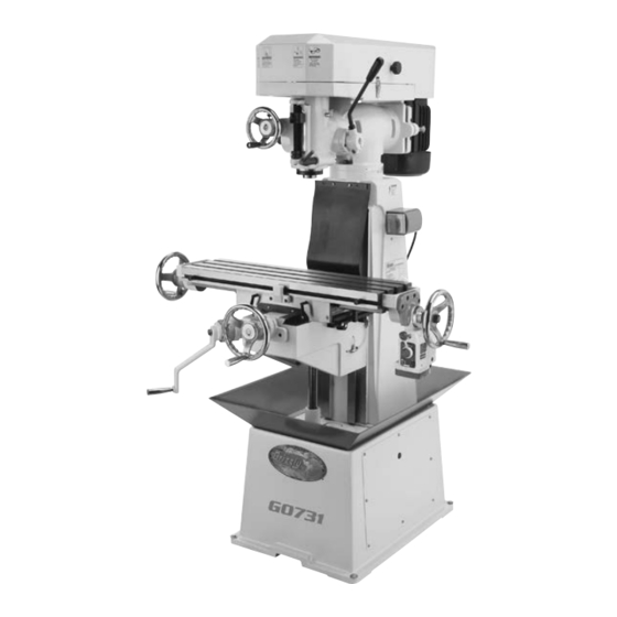
MODEL G0731
8" X 30" VERTICAL MILL
w/POWER FEED
OWNER'S MANUAL
(For models manufactured since 01/17)
COPYRIGHT © DECEMBER, 2011 BY GRIZZLY INDUSTRIAL, INC., REVISED JUNE, 2022 (BL)
WARNING: NO PORTION OF THIS MANUAL MAY BE REPRODUCED IN ANY SHAPE
OR FORM WITHOUT THE WRITTEN APPROVAL OF GRIZZLY INDUSTRIAL, INC.
#KN14570 PRINTED IN TAIWAN
V2.06.22
***Keep for Future Reference***
Advertisement
Table of Contents

Related Manuals for Grizzly G0731


Summary of Contents for Grizzly G0731
- Page 1 OWNER'S MANUAL (For models manufactured since 01/17) COPYRIGHT © DECEMBER, 2011 BY GRIZZLY INDUSTRIAL, INC., REVISED JUNE, 2022 (BL) WARNING: NO PORTION OF THIS MANUAL MAY BE REPRODUCED IN ANY SHAPE OR FORM WITHOUT THE WRITTEN APPROVAL OF GRIZZLY INDUSTRIAL, INC.
- Page 2 This manual provides critical safety instructions on the proper setup, operation, maintenance, and service of this machine/tool. Save this document, refer to it often, and use it to instruct other operators. Failure to read, understand and follow the instructions in this manual may result in fire or serious personal injury—including amputation, electrocution, or death.
-
Page 3: Table Of Contents
Table of Contents INTRODUCTION ..........2 SECTION 5: ACCESSORIES ......32 Contact Info............ 2 SECTION 6: MAINTENANCE ......33 Manual Accuracy ........... 2 Schedule ............33 Identification ........... 3 Cleaning & Protecting ........33 Controls & Components ......... 4 Lubrication ........... 33 Machine Data Sheet ........ -
Page 4: Introduction
Use this and other machinery with caution and respect. Failure to do so could result in serious per- sonal injury, damage to equipment, or poor Manufacture Date work results. Serial Number Model G0731 (Mfd. Since 01/17) -
Page 5: Identification
X-Axis Crank Handwheel Y-Axis Feed Limit Stop Track X-Axis Power Feed Cross Feed Handwheel Knee Front View Downfeed Selector Motor 1 ⁄ 110V/220V, Single Phase Turret Column Z-Axis Crank Handle Splash One-Shot Oiler Base Rear View Model G0731 (Mfd. Since 01/17) -
Page 6: Controls & Components
Figure 1. Downfeed controls viewed from the right side. Figure 2. Downfeed controls viewed from the left side. Model G0731 (Mfd. Since 01/17) - Page 7 X-axis should not move. in Forward (FWD) or Reverse (REV) direc- tion. Turns motor OFF in OFF position. K. Graduated Dial (Y-Axis): Displays Y-axis table movement in 0.001" increments. One full revolution represents 0.100" of table travel. Model G0731 (Mfd. Since 01/17)
- Page 8 X-Axis Power Feed Controls S. Power Feed Limit Switch: Stops table movement when either of the switch side Model G0731 is equipped with a power feed unit plungers are pressed by limit stops. for X-axis table movement. Refer to Figure 6 and...
-
Page 9: Machine Data Sheet
SHEET Customer Service #: (570) 546-9663 · To Order Call: (800) 523-4777 · Fax #: (800) 438-5901 MODEL G0731 MODEL G0731 8" X 30" 1‐1/2 HP VERTICAL MILL WITH 8" X 30" VERTICAL MILL WITH POWER FEED POWER FEED Product Dimensions: Weight................................ - Page 10 The information contained herein is deemed accurate as of 6/2/2022 and represents our most recent product specifications. Model G0731 PAGE 2 OF 2 Due to our ongoing improvement efforts, this information may not accurately describe items previously purchased. Model G0731 (Mfd. Since 01/17)
-
Page 11: Section 1: Safety
Everyday ery. Never operate under the influence of drugs or eyeglasses are not approved safety glasses. alcohol, when tired, or when distracted. Model G0731 (Mfd. Since 01/17) - Page 12 INTENdEd usAGE. Only use machine for its machine in good working condition. A machine intendedpurposeandnevermakemodifications that is improperly maintained could malfunction, not approved by Grizzly. Modifying machine or leadingtoseriouspersonalinjuryordeath. using it differently than intended may result in ChECK dAMAGEd PARTs. Regularly inspect...
-
Page 13: Additional Safety For Milling Machines
Use this machine with respect and caution to decrease the risk of operator injury. If normal safety precautions are overlooked or ignored, serious personal injury may occur. -11- Model G0731 (Mfd. Since 01/17) -
Page 14: Section 2: Power Supply
Nominal Voltage ..208V, 220V, 230V, 240V meets the requirements in the following section. Cycle ............60 Hz Phase ........... Single-Phase Power Supply Circuit ......15 Amps Plug/Receptacle ......NEMA 6-15 -12- Model G0731 (Mfd. Since 01/17) - Page 15 The plug must only be inserted into a matching receptacle (see following figure) that is properly installed and grounded in accordance with all local codes and ordinances. -13- Model G0731 (Mfd. Since 01/17)
- Page 16 Covers, guards, and safety devices on this machine are provided for your safety. Always keep them secured in place before connecting the machine to power to avoid serious personal injury. -14- Model G0731 (Mfd. Since 01/17)
-
Page 17: Section 3: Setup
IMPORTANT: Save all packaging materials until you are completely satisfied with the machine and have resolved any issues between Grizzly or the shipping agent. You MUST have the original pack- aging to file a freight claim. It is also extremely helpful if you need to return your machine later. -
Page 18: Inventory
Repeat Steps 2–3 as necessary until clean, then coat all unpainted surfaces with a quality metal protectant to prevent rust. Figure 11. Model G0731 inventory. NOTICE Avoid chlorine-based solvents, such as acetone or brake parts cleaner, that may damage painted surfaces. -
Page 19: Site Considerations
Only install in an Shadows, glare, or strobe effects that may distract access restricted location. or impede the operator must be eliminated. Wall Min. 30" = Electrical Connection for Maintenance 48" 68" Figure 12. Minimum working clearances. -17- Model G0731 (Mfd. Since 01/17) -
Page 20: Lifting & Placing
After removing the crate from the shipping pallet, wrap lifting straps around the turret, as shown in Figure 13, and securely attach them to your power lifting equipment. Lifting Straps Turret Figure 13. Example of positioning lifting straps. -18- Model G0731 (Mfd. Since 01/17) -
Page 21: Anchoring To Floor
Figure 15. Left X-axis table handwheel installed. Flat Washer Machine Base Lag Shield Anchor Concrete Drilled Hole Figure 14. Popular method for anchoring Handle machinery to a concrete floor. Figure 16. Handle attached to cross feed handwheel. -19- Model G0731 (Mfd. Since 01/17) -
Page 22: Initial Lubrication
However, some lubrication must be performed manually. Lubricate the spindle and quill before proceeding to the Test Run or Spindle Break-In sections. -20- Model G0731 (Mfd. Since 01/17) -
Page 23: Test Run
Complete the Initial lubrication procedures on Page 20 before proceeding. Failure to follow reasonable lubrication practices as outlined in this manual could lead to pre- mature failure of your mill and will void the warranty. -21- Model G0731 (Mfd. Since 01/17) - Page 24 Move direction lever to left, slowly turn speed dial clockwise to increase speed, then con- The Model G0731 comes with a power feed unit firm that table is moving to left. for X-axis table travel. Proper operation of the limit...
-
Page 25: Spindle Break-In
Adjust the pulleys to set the spindle speed to od to ensure proper power transmission 270 RPM (see Page 29 for detailed instruc- and avoid reducing life of belts. Refer to tion on Adjusting Spindle Speed). Tensioning/Replacing V-Belts on Page 35. -23- Model G0731 (Mfd. Since 01/17) -
Page 26: Section 4: Operations
Read books/magazines or get formal training before beginning any proj- ects. Regardless of the content in this sec- tion, Grizzly Industrial will not be held liable for accidents caused by lack of training. -24- Model G0731 (Mfd. Since 01/17) - Page 27 Use the table, saddle, and knee locks shown in Figures 21–22 to secure the table in position. Limit Block Table Locks Cross Limit Stops Figure 24. Cross limit stops and block. Figure 21. Location of table locks. -25- Model G0731 (Mfd. Since 01/17)
- Page 28 G. Power Lamp: Lights when the power feed is turned ON. H. Handwheel: Manually positions the table. Graduated Dial: Marked in 0.001" incre- ments, each complete revolution is equal to 0.100" of longitudinal table travel. -26- Model G0731 (Mfd. Since 01/17)
-
Page 29: Positioning Headstock
Figure 27. Example of head tilted 45° to the left. Figure 28. Example of head and turret rotated 45° to the left. Tools Needed Wrench 17mm............ 1 -27- Model G0731 (Mfd. Since 01/17) - Page 30 Unexpected movement of the head during cutter and workpiece. operations could cause the cutter to bind with the workpiece, resulting in personal injury, and possible damage to the cutter and workpiece. -28- Model G0731 (Mfd. Since 01/17)
-
Page 31: Setting Spindle Speed
Tensioning V-Belts on Page 35). Use the following formula to calculate the required spindle speed RPM: Recommended Spindle Cutting Speed (FPM) x 12 Speed Tool Dia. (in inches) x 3.14 (RPM) Double if using carbide cutting tool -29- Model G0731 (Mfd. Since 01/17) -
Page 32: Spindle Downfeed
Downfeed Stop Figure 34. Location of downfeed selector. Locking Wheel Quill Lock Fine Downfeed Figure 36. Location of downfeed stop controls. Handwheel Coarse Downfeed Handle Figure 35. Location of fine and coarse downfeed controls. -30- Model G0731 (Mfd. Since 01/17) -
Page 33: Loading/Unloading Tooling
-31- Model G0731 (Mfd. Since 01/17) -
Page 34: Section 5: Accessories
Made for ⁄ " T-slots. To reduce this risk, only install accessories recommended for this machine by Grizzly. NOTICE Refer to our website or latest catalog for additional recommended accessories. T10063—Milling Vise 12 ⁄... -
Page 35: Section 6: Maintenance
IMPORTANT: Before adding lubricant, clean debris and grime from the devices to avoid con- taminating the new lubrication. DISCONNECT MACHINE FROM POWER BEFORE PERFORMING LUBRICATION! -33- Model G0731 (Mfd. Since 01/17) - Page 36 Figure 45. One-Shot Pump Handle Figure 43. One-shot oiler components. Bevel Gears Figure 45. Vertical bevel gears. -34- Model G0731 (Mfd. Since 01/17)
-
Page 37: Tensioning/Replacing V-Belts
(see Figure 48). V-Belt Longitudinal Leadscrew Figure 46. Longitudinal leadscrew. Adjustment Bolt & Jam Cross Leadscrew Figure 48. V-belt tension adjustment bolt. Vertical Leadscrew Figure 47. Cross and vertical leadscrews. -35- Model G0731 (Mfd. Since 01/17) -
Page 38: Machine Storage
Bringing Mill Out of Storage Re-tension V-belts (refer to Page 35) if you loosened them for storage purposes. Repeat Test Run and Spindle Break-In pro- cedures, beginning on Page 21. -36- Model G0731 (Mfd. Since 01/17) -
Page 39: Section 7: Service
5. Replace unbalanced chuck; replace/resharpen cutter; use correct feed rate. 6. Centrifugal switch needs adjustment/at 6. Adjust/replace if at fault fault. 7. Motor bearings at fault. 7. Test by rotating shaft; rotational grinding/loose shaft requires bearing replacement. -37- Model G0731 (Mfd. Since 01/17) - Page 40 5. Replace clutch. Operates at high 1. Rapid micro switch is stuck. 1. Lightly tap on it to lower it. speed only or is 2. Wiring harness unplugged from circuit 2. Reconnect wiring harness. inconsistent. board. -38- Model G0731 (Mfd. Since 01/17)
-
Page 41: Adjusting Gibs
Refer to Figures 50–52 for the locations of the table, saddle, and knee gib adjustment screws. Tool Needed Screwdriver Flat Head #2 ........1 Knee Gib Adjustment Screw (1 of 2) Figure 52. Knee gib adjustment screw (1 of 2). -39- Model G0731 (Mfd. Since 01/17) -
Page 42: Adjusting Backlash
Tighten or loosen the cap screws on the leadscrew nuts shown in Figures 53–54, then test the amount of backlash by slowly rocking the handwheels back-and-forth. Longitudinal Screws Leadscrew Nut Figure 53. Longitudinal leadscrew nut. Screw -40- Model G0731 (Mfd. Since 01/17) -
Page 43: Tramming Spindle
Figure 56. Dial test indicator mounted. Items Needed Dial Test Indicator (w/at least 0.0005" resolution) ......1 Indicator Holder (mounted on the quill/spindle) ......1 Precision Parallel Block (at least 9" in length) .......... 1 -41- Model G0731 (Mfd. Since 01/17) - Page 44 Repeat Steps 6–7 until you are satisfied with the so the head does not move loosely while you spindle axis alignment along the table adjust it. Remember to tighten all the tilt lock X-axis. -42- Model G0731 (Mfd. Since 01/17)
-
Page 45: Section 8: Wiring
Technical source. Support at (570) 546-9663. The photos and diagrams included in this section are best viewed in color. You can view these pages in color at www.grizzly.com. -43- Model G0731 (Mfd. Since 01/17) -
Page 46: Wiring Diagram
Front Ground View Switch Box Figure 60. Switch box location. Plug Rewired for 220V Ground 6-15 Plug (As Recommended) Rear Neutral View 5-15 Plug Ground 110 VAC Ground READ ELECTRICAL SAFETY -44- Model G0731 (Mfd. Since 01/17) ON PAGE 43! -
Page 47: Section 9: Parts
SECTION 9: PARTS We do our best to stock replacement parts when possible, but we cannot guarantee that all parts shown are available for purchase. Call (800) 523-4777 or visit www.grizzly.com/parts to check for availability. Head 109 110 130-1 BUY PARTS ONLINE AT GRIZZLY.COM! -45- Model G0731 (Mfd. - Page 48 BEARING SPACER SMALL P0731159 LOCK HANDLE P0731130 SPINDLE P0731160 DRAWBAR 7/16-20 X 12-3/8 W/NUT 130-1 P0731130-1 SET SCREW M4-.7 X 10 BUY PARTS ONLINE AT GRIZZLY.COM! -46- Model G0731 (Mfd. Since 01/17) Scan QR code to visit our Parts Store.
-
Page 49: Drive System
212V2 P0731212V2 LOCK WASHER 12MM V2.01.17 P0731237 PULLEY SWIVEL PIN 213V2 P0731213V2 HEX NUT M12-1.75 V2.01.17 P0731238 INT RETAINING RING 45MM BUY PARTS ONLINE AT GRIZZLY.COM! -47- Model G0731 (Mfd. Since 01/17) Scan QR code to visit our Parts Store. - Page 50 PHLP HD SCR M6-1 X 16 P0731327 GIB ADJUSTMENT SCREW 344-9 P0731344-9 FLAT WASHER 6MM P0731328 SADDLE LOCK SCREW 344-10 P0731344-10 POWER FEED ADAPTER GEAR BUY PARTS ONLINE AT GRIZZLY.COM! -48- Model G0731 (Mfd. Since 01/17) Scan QR code to visit our Parts Store.
-
Page 51: Knee & Base
Knee & Base 457 456 468 469 461 462 441-1 BUY PARTS ONLINE AT GRIZZLY.COM! -49- Model G0731 (Mfd. Since 01/17) Scan QR code to visit our Parts Store. - Page 52 P0731434 BEARING HOUSING P0731469 HEX WRENCH 5MM P0731435 CROSS FEED LEADSCREW P0731470 WRENCH 12 X 14MM OPEN-ENDS P0731436 BALL BEARING 6204ZZ BUY PARTS ONLINE AT GRIZZLY.COM! -50- Model G0731 (Mfd. Since 01/17) Scan QR code to visit our Parts Store.
-
Page 53: Labels & Cosmetics
Safety labels help reduce the risk of serious injury caused by machine hazards. If any label comes off or becomes unreadable, the owner of this machine MUST replace it in the original location before resuming operations. For replacements, contact (800) 523-4777 or www.grizzly.com. BUY PARTS ONLINE AT GRIZZLY.COM! -51- Model G0731 (Mfd. - Page 54 -52- Model G0731 (Mfd. Since 01/17)
-
Page 55: Warranty & Returns
WARRANTY & RETURNS Grizzly Industrial, Inc. warrants every product it sells for a period of 1 year to the original purchaser from the date of purchase. This warranty does not apply to defects due directly or indirectly to misuse, abuse, negligence, accidents, repairs or alterations or lack of maintenance.
Need help?
Do you have a question about the G0731 and is the answer not in the manual?
Questions and answers