Table of Contents
Advertisement
Quick Links
INSTRUCTIONS–PARTS LIST
This manual contains important
warnings and information.
READ AND KEEP FOR REFERENCE.
INSTRUCTIONS
Parts
US Patent Pending
HVLP–Turbine Guns
10 psi (0.07 MPa, .7 bar) Maximum Inlet Air Pressure
50 psi (0.35 MPa, 3.5 bar) Maximum Inlet Fluid Pressure
Cup Feed
Includes 1-quart (1 liter) cup
Model 244113, without fluid set
Model 244117, with # 3 fluid set
GRACO INC. P.O. BOX 1441 MINNEAPOLIS, MN 55440–1441
ECOPYRIGHT 2000, GRACO INC.
Graco Inc. is registered to I.S. EN ISO 9001
T10746
Remote Pressure Feed
Model 244115, without fluid set
Model 244118, with # 3 fluid set
309205
Rev. D
Advertisement
Table of Contents

Related Manuals for Graco HVLP Series


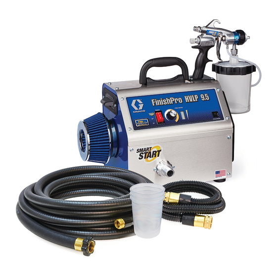
Summary of Contents for Graco HVLP Series
- Page 1 Model 244113, without fluid set Model 244118, with # 3 fluid set Model 244117, with # 3 fluid set GRACO INC. P.O. BOX 1441 MINNEAPOLIS, MN 55440–1441 ECOPYRIGHT 2000, GRACO INC. Graco Inc. is registered to I.S. EN ISO 9001...
-
Page 2: Table Of Contents
........CAUTION Graco Standard Warranty ..... . - Page 3 D Use the equipment only for its intended purpose. If you are not sure, call your distributor. D Do not alter or modify this equipment. Use only genuine Graco parts and accessories. D Check equipment daily. Repair or replace worn or damaged parts immediately.
-
Page 4: Introduction
Introduction Features The Graco HVLP–Turbine Gun features a quick–change fluid set, EasyGlidet trigger and easy–access controls. One air cap fits all six fluid sets. Air flow control Pattern adjustment knob Fluid flow and pattern size control Air cap EasyGlidet Trigger... - Page 5 Setup Fluid Flow 3. If further gun fluid adjustment is needed, turn fluid adjustment knob (21) clockwise to reduce volume 1. To obtain maximum fluid flow, turn fluid adjustment of fluid output. See Fig. 4. knob (21) counterclockwise until the trigger (10) moves freely.
- Page 6 Setup NOTES: Adjusting the Pattern D Control over-spray mist by using only as much air Change the pattern by adjusting the fluid knob (21) as necessary to spray fluid. Lighter fluids require and pattern selection knob (A). less air. D If atomization is still unacceptable, fluids may be NOTE: Reducing the fluid flow rate or turning the air thinned further or a different fluid set may be re- knob to RND will reduce the pattern width.
- Page 7 For low flow rates or light viscosity fluid, select smaller nozzle sizes. For high flow rates or high viscosity fluid, select larger nozzle sizes. Graco offers six different fluid sets: TI0824 Fig. 9 Fluid Set Part Number Orifice Size (inch) 244123 0.032...
- Page 8 Setup Contractor Fluid Set Chart Use this chart to determine Fluid Set for specific contractor application. Fig. 10. Fig. 10 Installing the Fluid Set 4. Insert the needle assembly (14b) into the back of CAUTION the gun. Replace the nozzle (14a) air cap housing (15) and air cap retaining ring and tighten by hand.
- Page 9 Setup Preparing to Spray Test consistency, remove stir stick from thinned paint. Consistency is right when first drops from stir stick are about one second apart. Paint Reduction — Industrial or Domestic Coatings Reduce and catalyze all paint to manufacturer’s Prepare the Surface specifications.
- Page 10 Setup Turbine Spray Unit (for more information 1. Connect gun air supply hose (A) between turbine air outlet (B) and gun air inlet (C). DO NOT use see manual 309241) wrench to tighten connections; hand tighten only. See Fig. 12. Connect the Fluid and Air Supply 2.
- Page 11 Setup Fill Cup or Remote Pressure Pot b. 2 -gallon remote pressure pot: Pull pressure relief valve ring (206c) until Spray Gun Cup pressure is completely relieved. WARNING 2-quart remote pressure pot: Turn out pressure relief knob (113) one turn. The spray gun cup is pressurized by the gun’s air Wait until pressure is completely relieved supply.
-
Page 12: Spraying Techniques
Spraying Techniques General Spraying Techniques Automotive Spraying Techniques D When blending spots, work from outside in. D Select proper fluid set. To determine correct fluid D Two 20-foot (6.1 m) hoses are recommended when set see charts on page 8. applying automotive finish coats. - Page 13 Spraying Techniques Swivel Tube Adjustment The adjustable swivel tube allows the HVLP–Turbine Gun to be held in any position why spraying. To adjust the position of the tube in the cup: 1. Loosen the nut (A) with a wrench (42). 3.
-
Page 14: Maintenance
Maintenance Cleaning the Spray Gun 6. With the gun pointed down, clean the front of the gun, using the soft-bristle brush and solvent. 1. Clean gun and cup by hand with compatible solvent or place them in gun washer with trigger held open;... - Page 15 Maintenance 8. Trigger gun while hand tightening the fluid nozzle 11. Lubricate gun after cleaning it as instructed on (14a). page 17. 9. Install air cap (15) and retaining ring (13). 10. Dampen a soft cloth with solvent. Wring out the excess.
- Page 16 Maintenance Flushing the Spray Gun Using a Remote Flushing the Spray Gun and Cup Pressure Pot 1. Turn off air supply to gun. NOTES: 2. Unlatch cup cover, and remove cup from cover. D Check for any fluid leakage from gun and fluid hoses.
-
Page 17: Service
Service Lubricating the Spray Gun Replacing the Needle After cleaning or servicing gun, lubricate parts WARNING indicated in Fig. 23 with silicone-free spray gun lubricant or similar material. PRESSURIZED EQUIPMENT HAZARD To reduce the risk of a serious injury, follow the D All threaded areas (A) Pressure Relief Procedure on page 11 before D Trigger screws (B) - Page 18 Service Replacing the Air Valve (243840) 3. Put the o–ring on the new duckbill valve. The air valve (25) cannot be repaired. If it is damaged, 4. Press the new duckbill valve and o–ring onto the the entire piece must be replaced. lid.
-
Page 19: Troubleshooting
Troubleshooting Spray Finish Problems PROBLEM CAUSE SOLUTION D Maintain proper spraying distance. Orange peel finish — Paint Paint droplets too large surface not smooth See page 12. D Keep the turbine air filters clean to allow full air flow. D Do not use an air hose that is too long to provide sufficient atomization pressure. - Page 20 Troubleshooting Spray Gun Problems PROBLEM CAUSE SOLUTION No or slow fluid flow, Wrong size fluid set being used or the Select the proper fluid set for the fluid intermittent spray, or o–ring on nozzle is missing being sprayed (see page 8) or put an fluttering spray o–ring on the nozzle.
-
Page 21: Accessories
Technical Data Maximum inlet fluid pressure ........... . 50 psi (0.35 MPa, 3.5 bar) Maximum inlet air pressure . - Page 22 Parts for HVLP–Turbine Gun Model Nos. 244113, 244115, 244117, 244118 TI0745 309205...
-
Page 23: Parts
Parts for HVLP–Turbine Gun Model Nos. 244113, 244115, 244117, 244118 Ref. Part No. Description Qty. Ref. Part No. Description Qty. 244426 BODY, gun 243840 VALVE, air fan 244429 HOUSING, nozzle 243842 VALVE, air 112085 PACKING, o–ring 196463 TUBE, handle 113137 PACKING, o–ring 196468 FITTING, adapter... -
Page 24: Graco Standard Warranty
Graco distributor to the original purchaser for use. With the exception of any special, extended, or limited warranty published by Graco, Graco will, for a period of twelve months from the date of sale, repair or replace any part of the equipment determined by Graco to be defective.
Need help?
Do you have a question about the HVLP Series and is the answer not in the manual?
Questions and answers